-
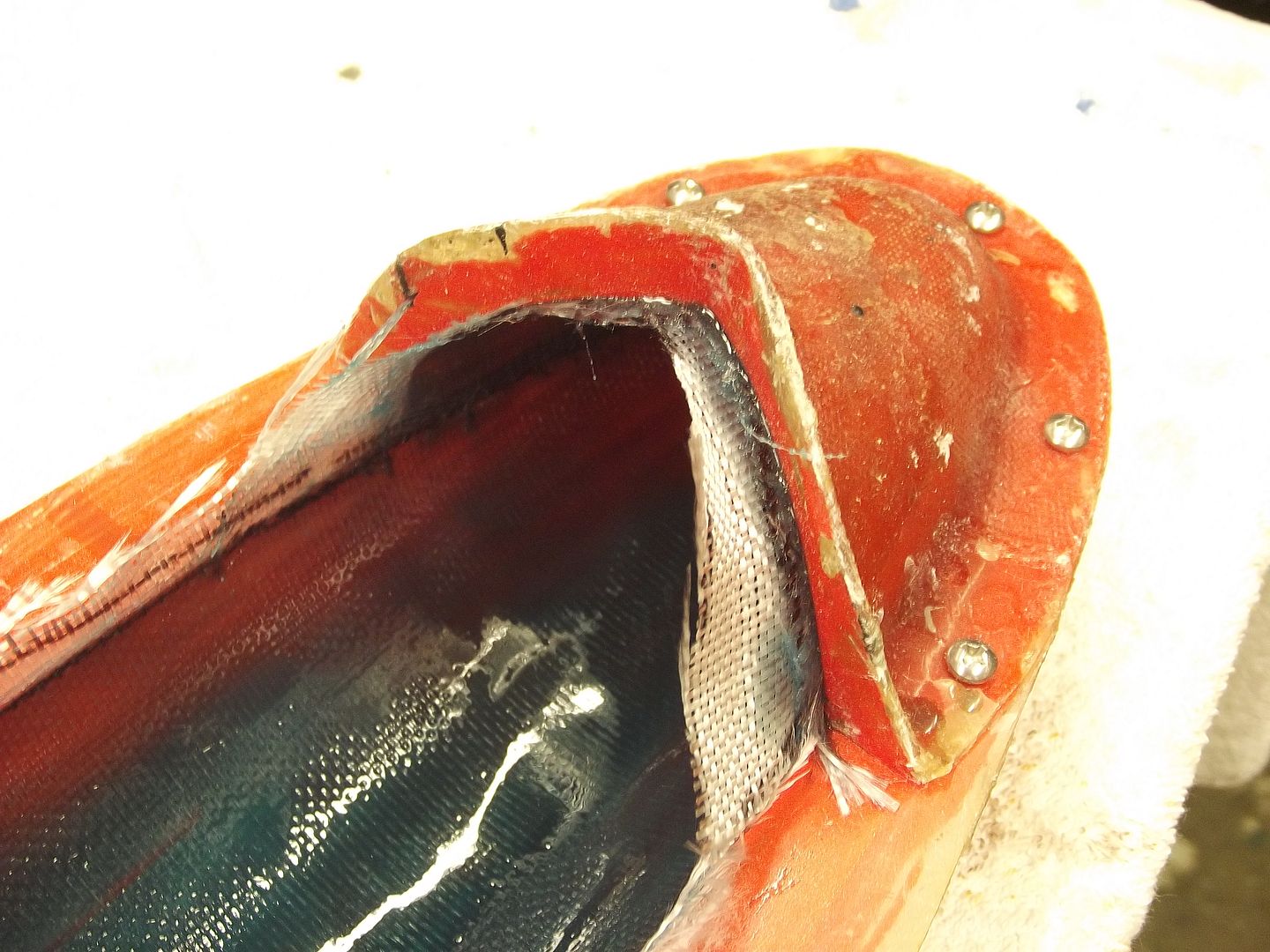
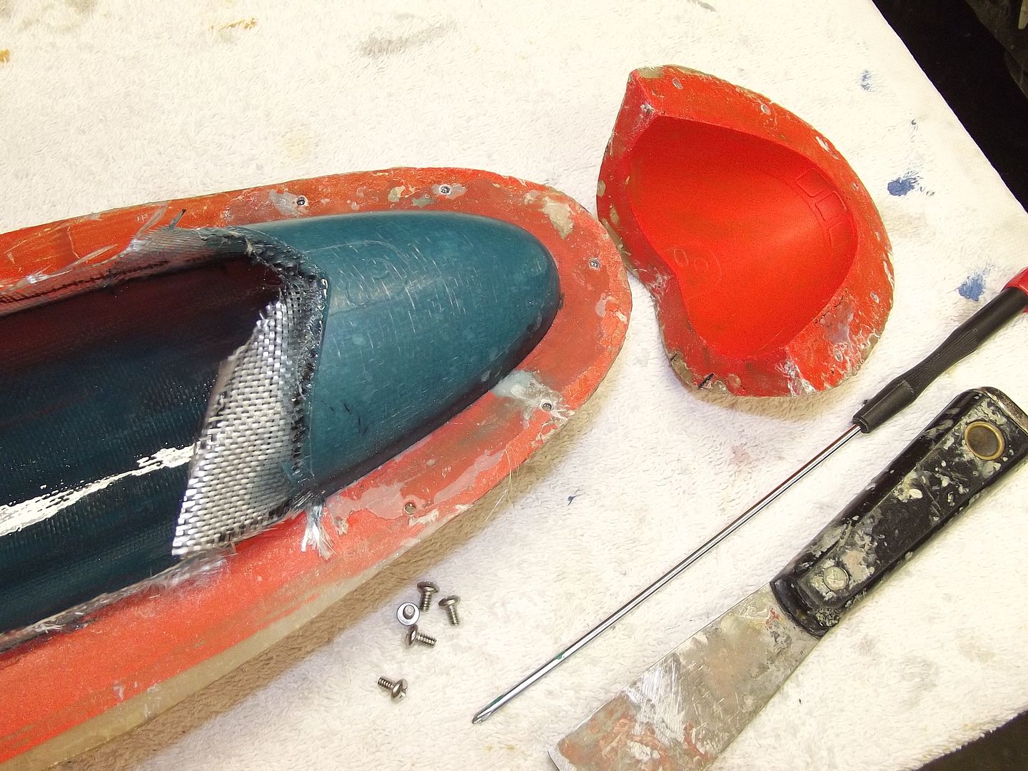
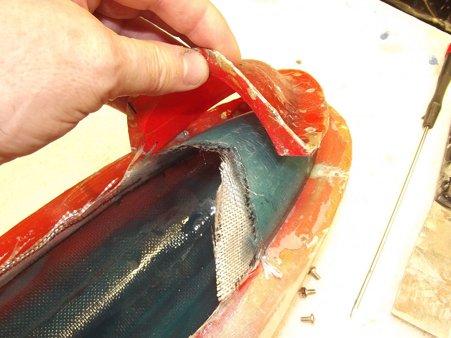
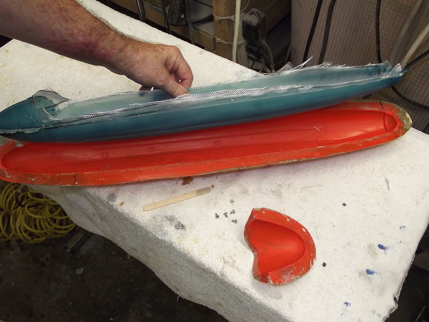
I read about your diveplane casting mishap and STILL I managed to forget the release agent. A sharp knife it is. -
No sweat, use a very sharp knive to follow the lines from your topmold, offcourse before you start to reinforce the lower mold, happened to me with making my divingplanes from the V80 , simply used a knive, it saved me making another mold.
Manfred.Leave a comment:
-
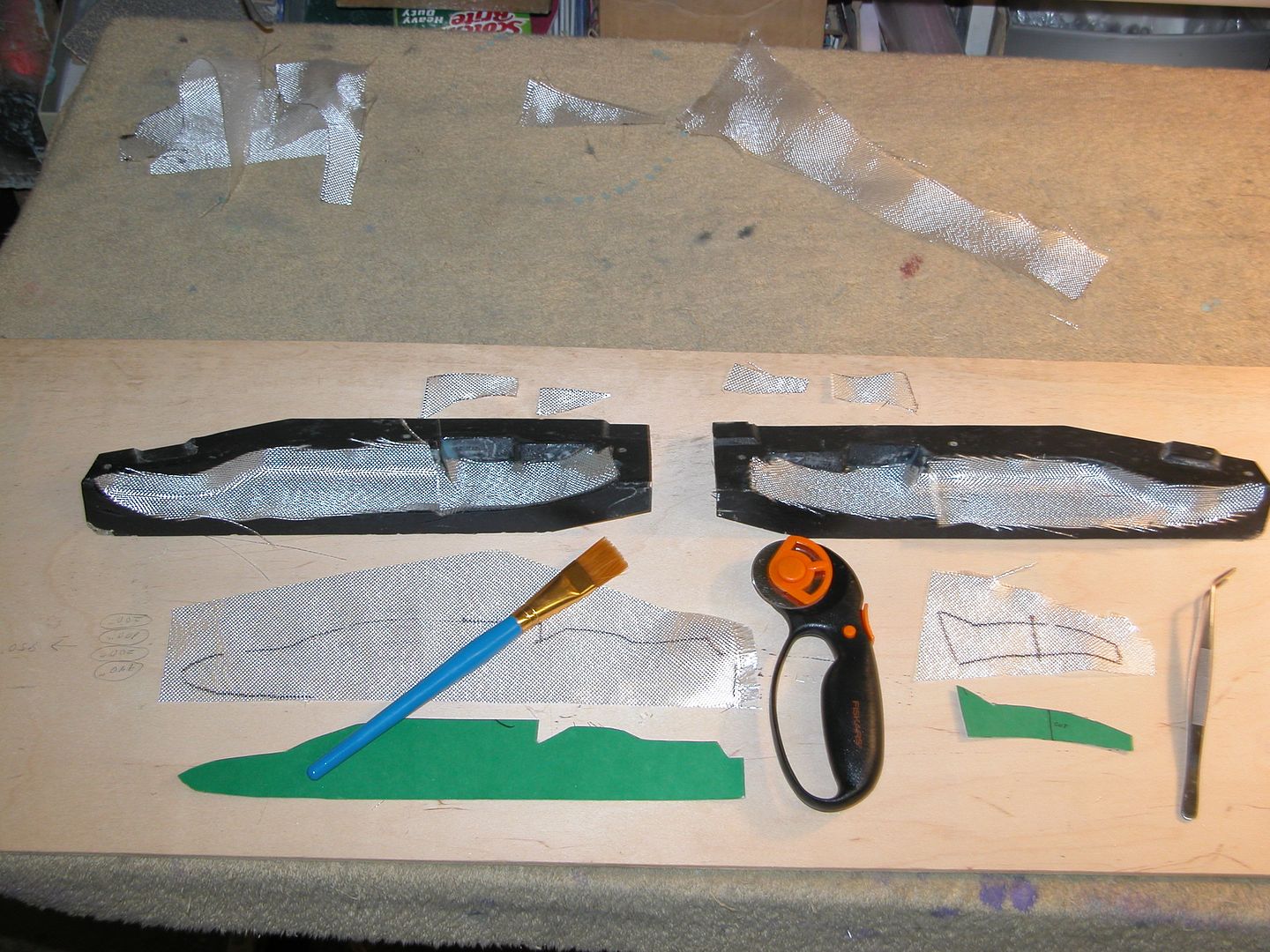
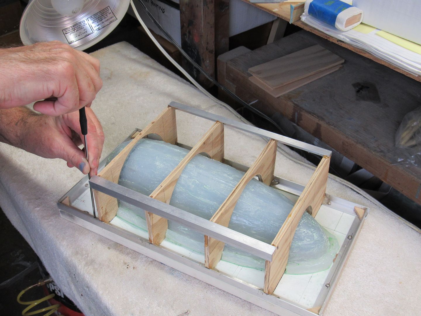
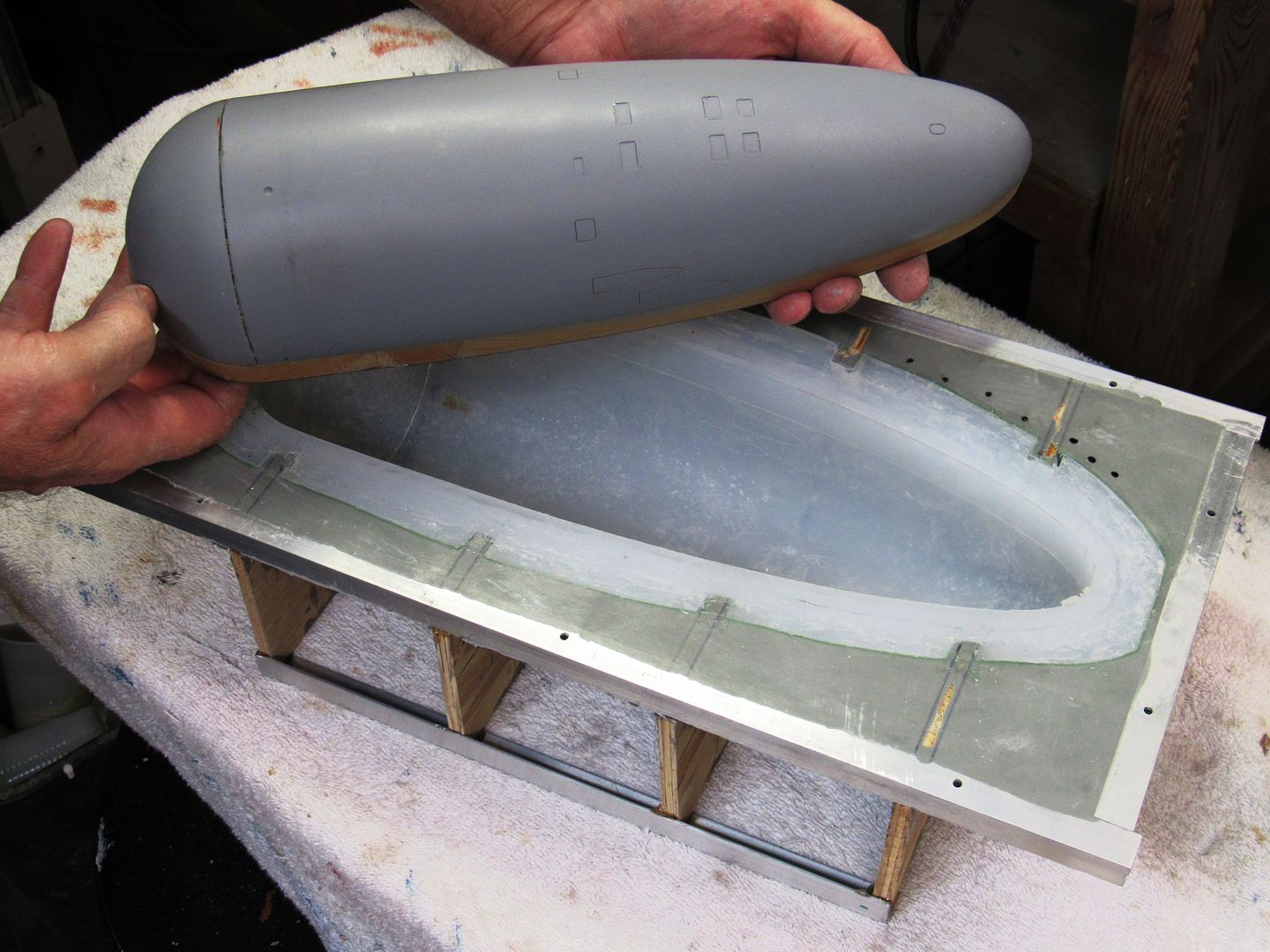
Getting on with the bottom hull halves.
Thos is the lower right half in the moulding frame.
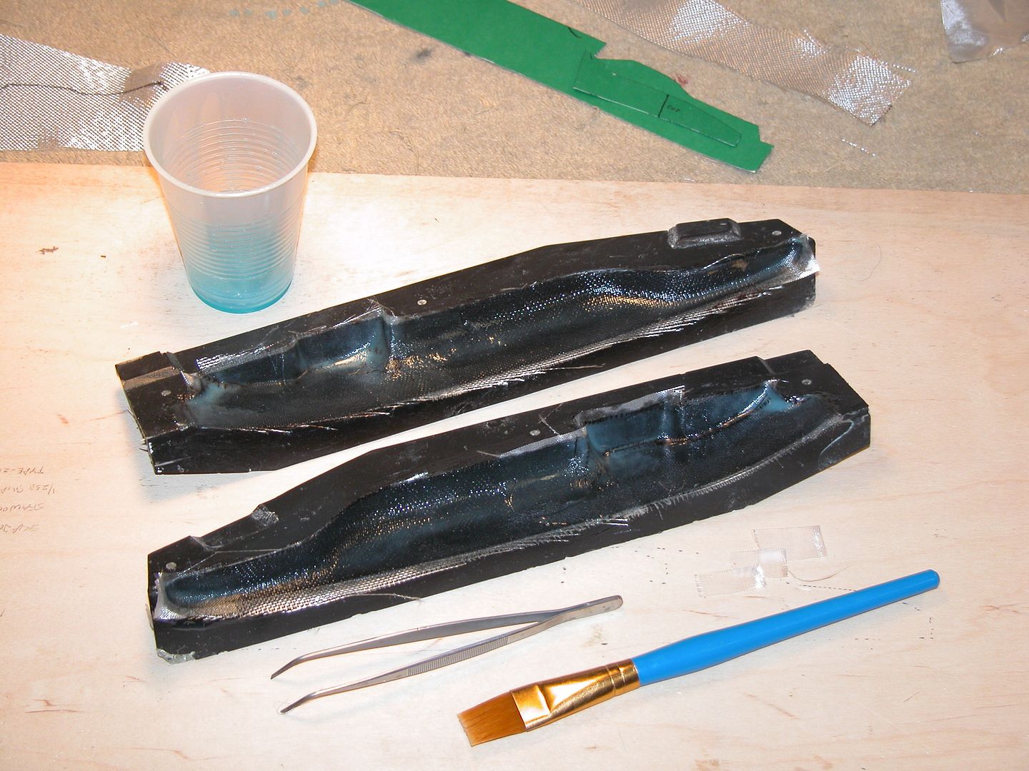
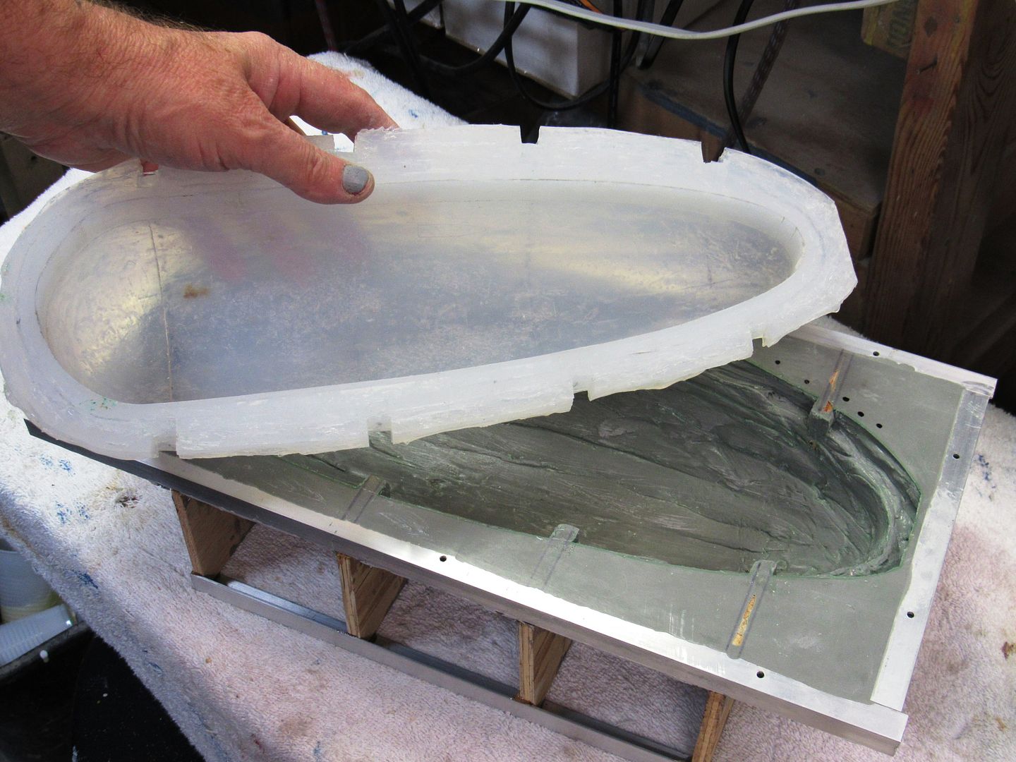
And post gloop. The gloop in question is a two part silicon rubber with a thickening agent. Once it goes off I'll add some structural support and fibreglass to create the lower right mould. I'm in for some fun later on however, because I FORGOT TO SPRAY THE BLOODY THING WITH RELEASE AGENT!!! The silicon will part with the plug and the other bits and pieces but it will stick to the silicon in the upper mould like **** to a blanket.Leave a comment:
-
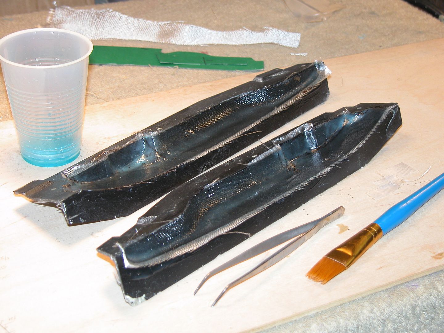
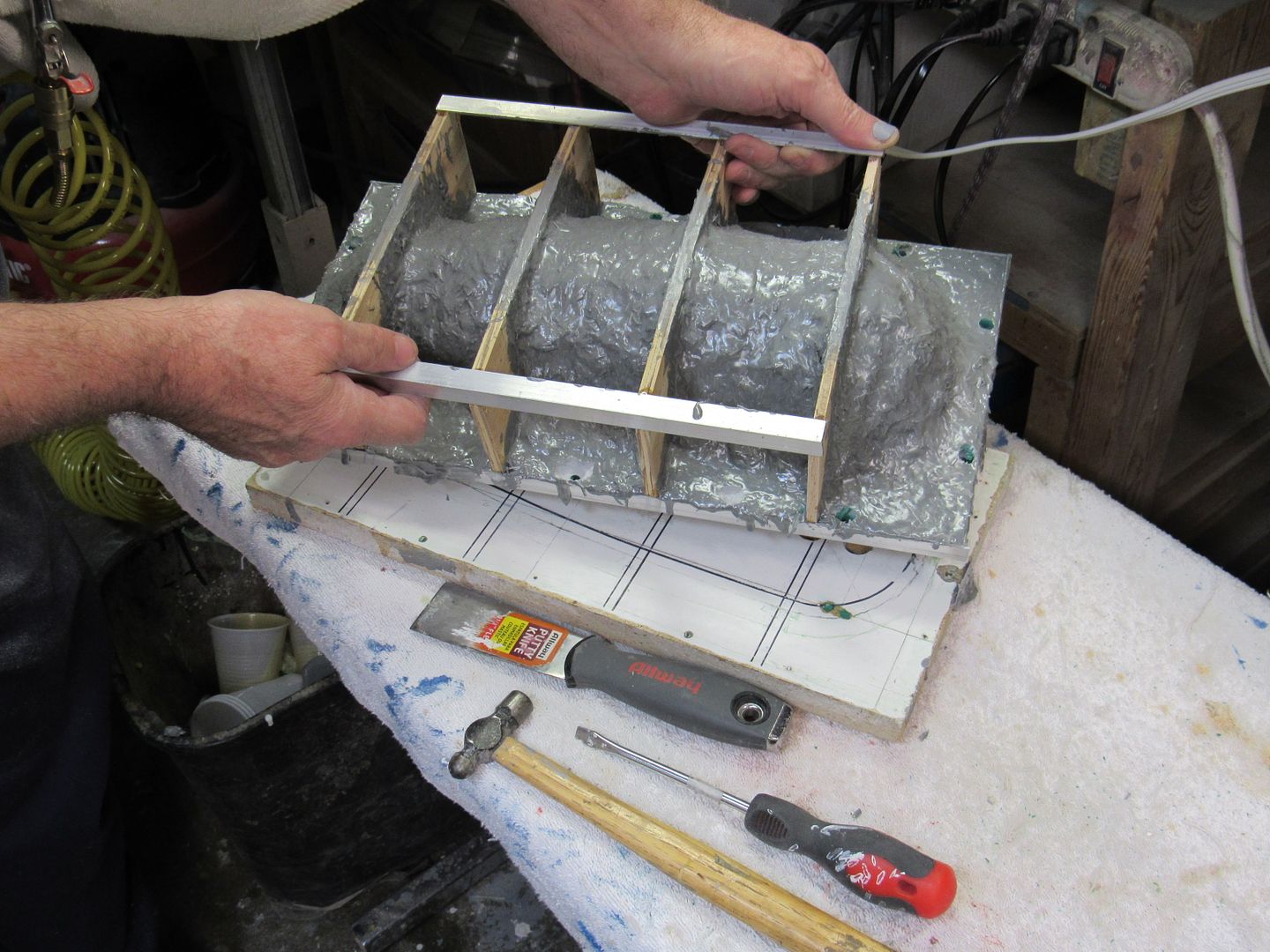
The rubber is about 1/2" at the top, a bit thicker at the sides. I agree the paint looks a bit too "green". Lighter and maybe a bit yellower would be better.Leave a comment:
-
Man! You're going like a house-a-fire on this project! How thick did you build up the rubber? Love how you jack the hull up to the waterline. This is the exciting part! Lighten the green just a tad.
DavidLeave a comment:
-
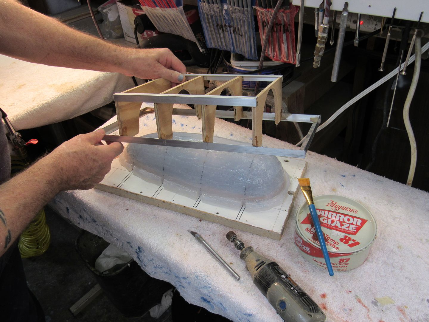
The plug has been mounted on the parting board...... these are the adjusters to get it level and at the right waterline cut off.Once it had been glooped with silicon, I gave it one cat of resin and then dropped the egg crate over it.
Then another two layers of chopped glass and resin. Meanwhile I have been seeking out the right colour for the great leader's chariot. How abot this?
Leave a comment:
-
Kind of. I do a complete lay-up into each half -- gel-coat, 4 oz., then two laminates of 10 oz., taking care not to get any above the flange plane. Only then do I assemble the tool and lay in glass from the open end to bridge the flange plane, bonding the two GRP sections together. I then open up the tool and pop the completed GRP part out.
You see us doing this with the Dave Manley 1/96 BLUEBACK and KILO tooling here:
More pretty pictures from the BLUEBACK album: http://s262.photobucket.com/user/dme...eshow/BLUEBACK
Another way to work GRP parts out of hard-shell tools is to over-extend the glass work over the flange-plane, and then sand back the excess GRP to the flange-plane, re-wax the flange, assemble the two halves, and bond the union between the two with glass tape and resin, like on this superstructure for a 1/72 M-1 model:
DavidLeave a comment:
-
OK. That's interseting and it raises another question. When you use this tool do you gel coat both sides, lay the cloth and wet it and THEN join the tool together or is it done in some other way?Leave a comment:
-
Oh! It's a laid-up GRP part pulled off this tool.
DavidLeave a comment:
-
And this is just the way a WIP should work: questions are asked, qualified personnel answer. Let's keep this ball rolling, HardRock!
The mother mold (substrate, if you will) is any thermosetting plastic you like: glass impregnated with polyester, polyurethane or epoxy, for example. The 212 mother mold is a purpose formulated polyurethane marketed by the Freeman Pattern and Supply Company, https://www.freemansupply.com/
This 'tooling resin' is formulated for non-sag, quick cure, and stability over time and temperatures -- the stuff is very good for vacuforming tools as well. In this application, it's used with fiberglass shards to form the stiff mother mold portion of the Type-212 tools. Here's the product sheet, https://www.freemansupply.com/produc...-cast-urethane
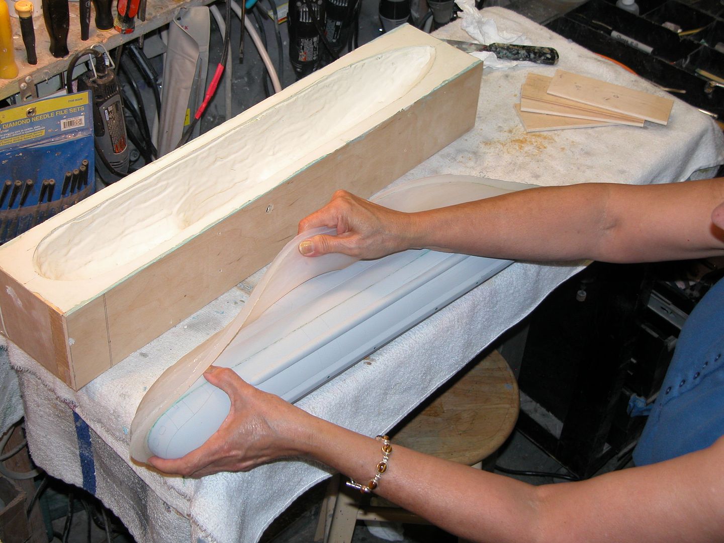
And here's the process of mother mold build-up over the glove mold:
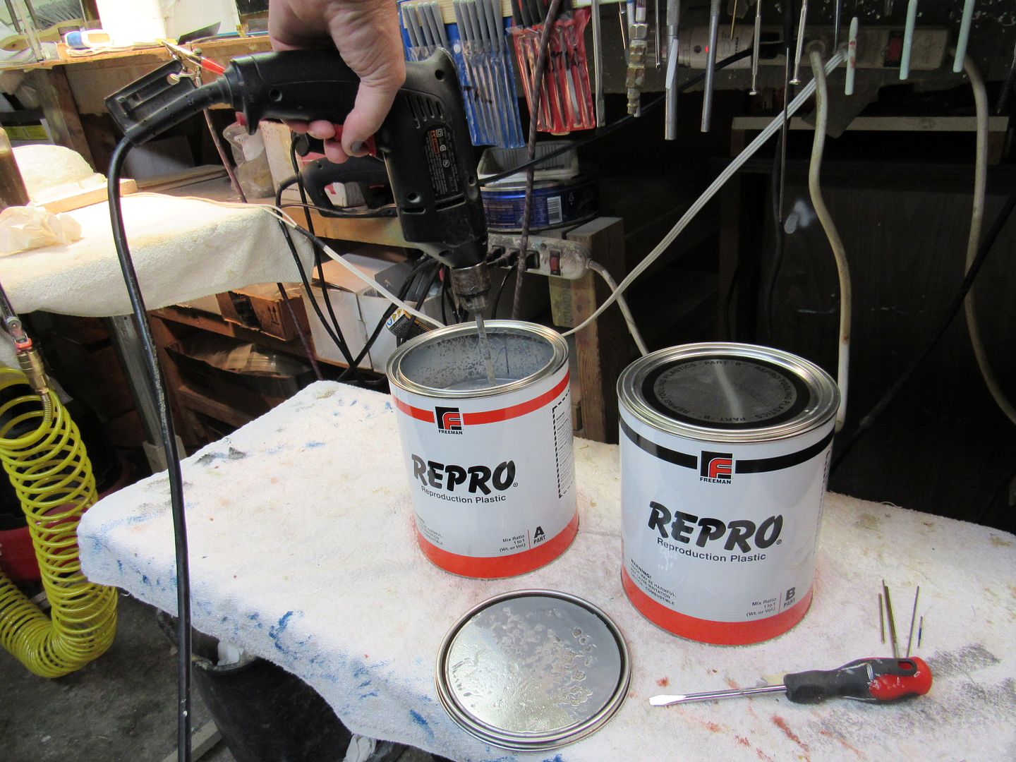
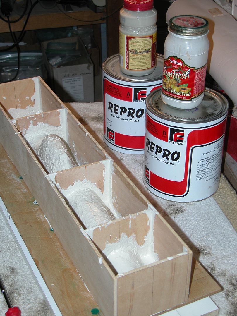
I'll first show the work on the Type-212. In this case I'm using the polyurethane tooling resin reinforced with glass fibers. First task is to thoroughly mix each of the two-part system, very heavily filled and very thick. A 'jiffy-mixer' is a must for complete mixing. Once mixed, I transfer a small quantity to ready service containers -- that way I don't expose the bulk material to air any longer than I have to.
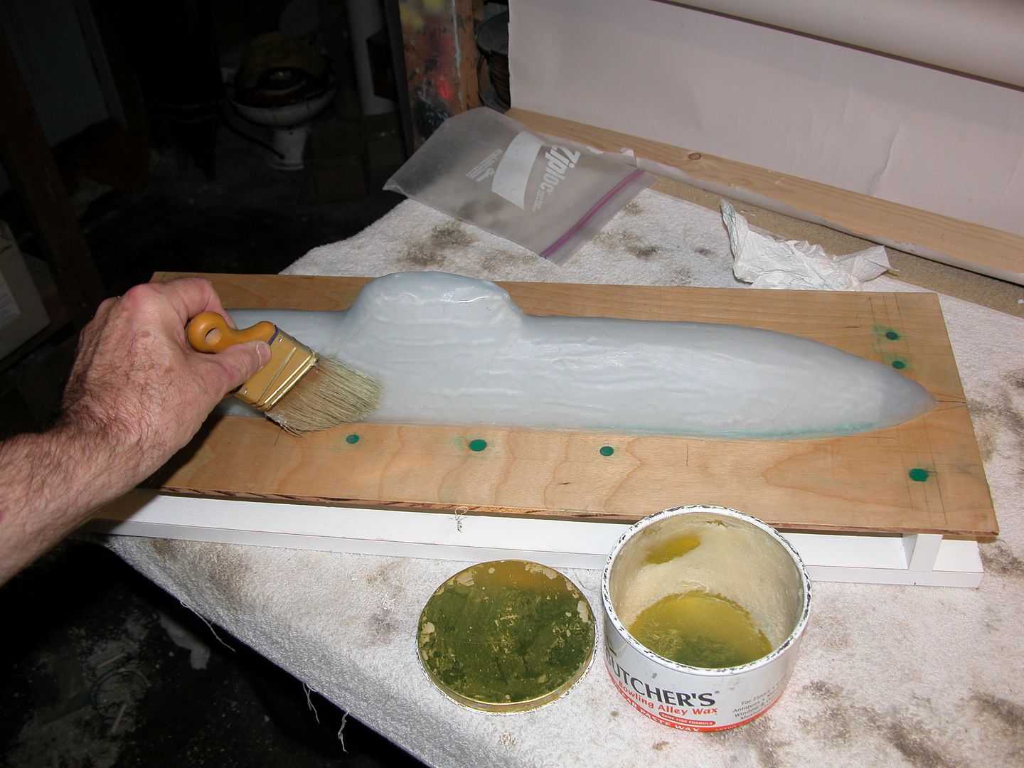
The surface of the rubber glove mold is waxed to ease later release between it and the mother mold. A small quantity of tooling resin is mixed up and brushed over the surface of the glove mold and left to harden, but still a bit tacky -- about ten minutes from mixing. Note that the surface of the rubber glove is rough -- this insures a tight indexing between glove and mother molds.
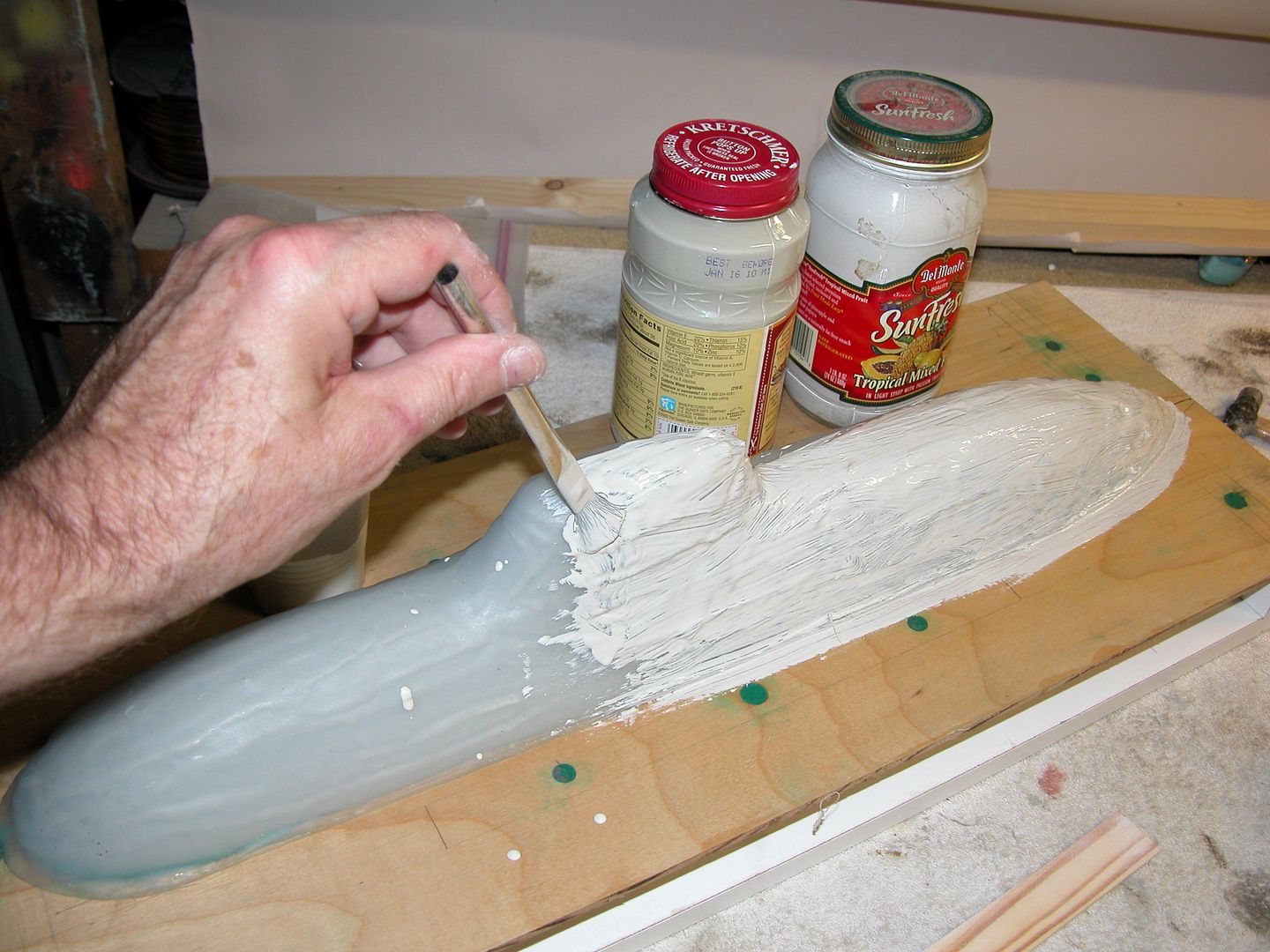
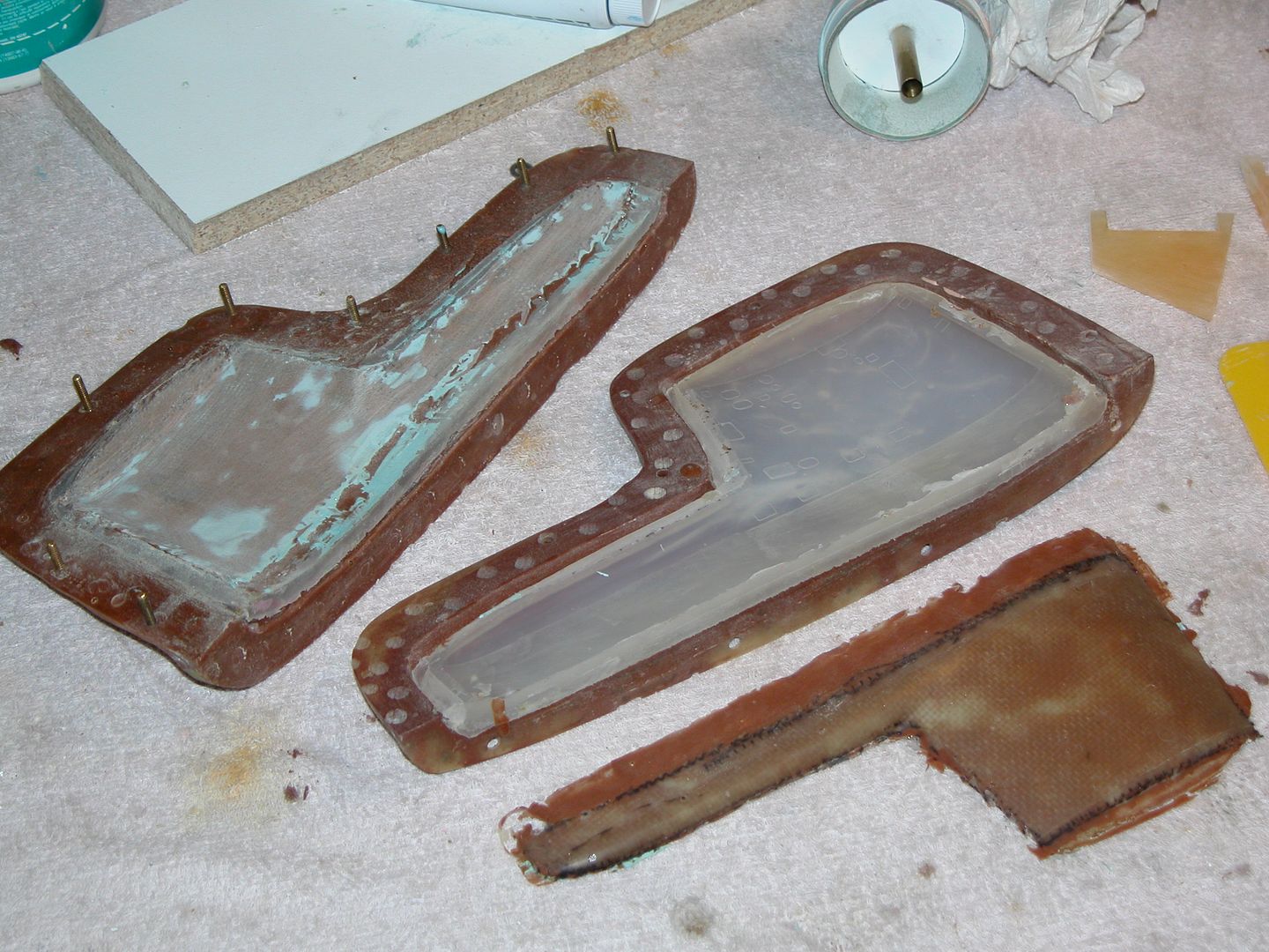
An egg-crate type reinforcement is made from plywood and bonded to the mother mold as layers of tooling resin are piled onto the glove, after the first coat, glass fibers are added to the mix to strengthen the mother mold. Note that the mix overlaps and bonds to the egg-crate. The assembly forms a very stable, rigid structure that will not warp over time. Nominal wall thickness of the mother mold is about 3/8".
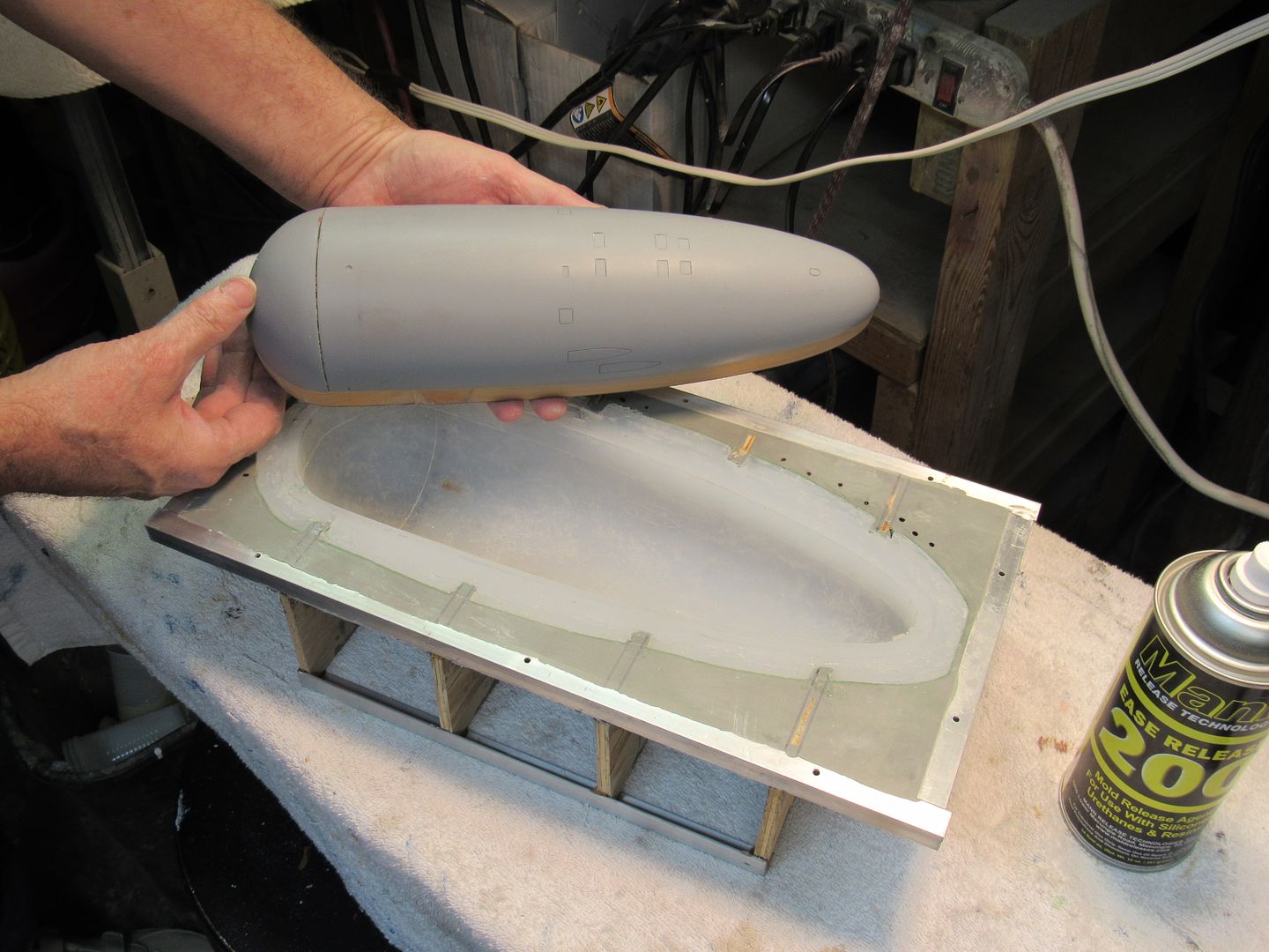
Here's the same process applied to the master of a 1/96 THRESHER bow section, glove and mother mold:
I don't understand your last question, pal. Would you re-phrase is please.
David
Leave a comment:
-
Questions, questions, questions. Standby for questions. What is the substrate used in the 212 mould to encase the rubber? What sort of gel coat did you use? In the last photograph; is that a plug at the bottom, and if it is, how on earth do you stop it getting welded to the moulding?Leave a comment:
-
Damn you, that looks good. I have yet to write up a worthwhile WIP on the glove-mother mold process. So, here are the pretty pictures. Just keep this in mind, you want the wall thickness of the rubber glove to be no less than 1/2". Thicker is better.
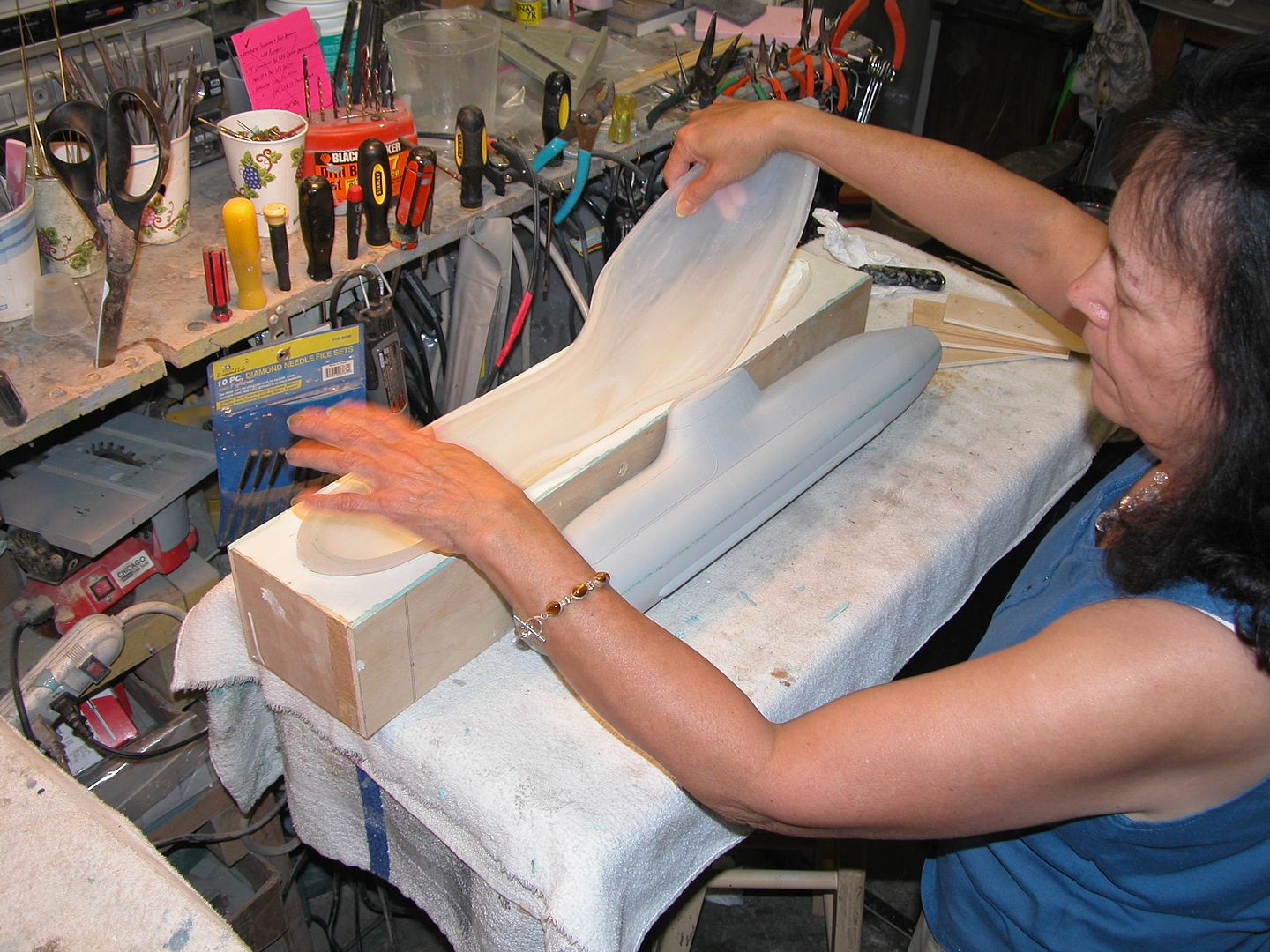
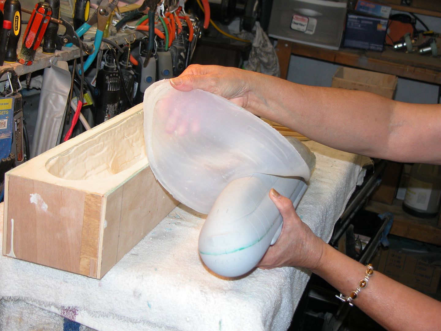
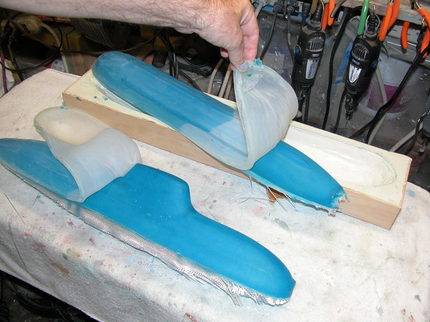
More pretty pictures:
DavidLeave a comment:
-
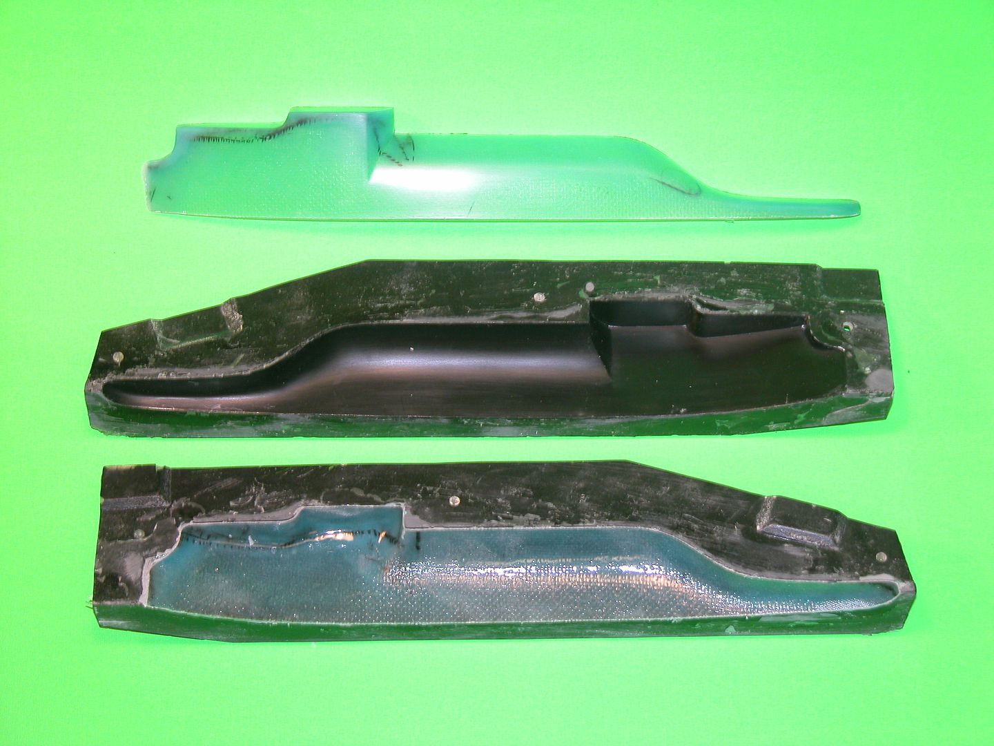
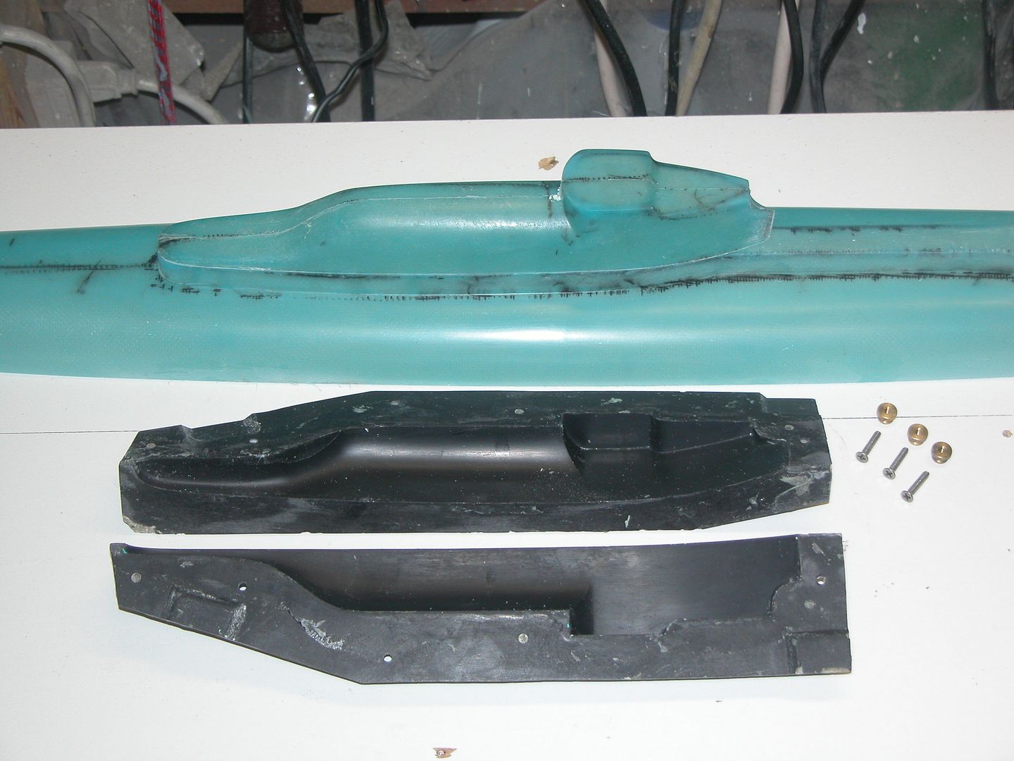
This is better. The attachments are still raw and need some sanding but this is the general idea.
Attached FilesLeave a comment:
-


Leave a comment: