
Thankyou David,
As mentioned earlier I would now enter the nitty gritty stage of building the finished product. This write up may be useful if people don't get my drawings, photos or plain old explanation that I have put into my instruction manual. Yes David your manuals are very thorough. I am actually in the process of getting hold of ones that Hardrock has accumulated in his recent build efforts to see what sort of content other people cover in their manuals. I am very intrigued by his build of the Soviet Uniform class. That thing is coming along soo fast!!
Anyway back to the build up. The tail fins take the most work and are quite fiddly. I have devoted probably most of my build time to getting the tail configured. It is the business end of the boat after all and has taken the most amount of development with appendages and the like. One both top and bottom hull had been sanded back and were level on the board I would look at the placement of the rear fins. I marked out the placement of the fixed planes. On the top and bottom mould I have moulded an outline of where they go. You take a file and cut out the profile of the square section left over from the sprue. Only half a square because the top hull be the other half. File out a half round for the pivot. Placing a brass rod through both and getting them level relative to the edges of the bottom hull is crucial. I did find that the filleting did not follow exactly the line of the hull. This was a mild inconvenience and something that the modeller who embarks on this kit will find. Sorry , However easily fixed. Either sand back a bit at front of the plane or fill in the back with filler. I did the latter. gives you slightly more surface area. This is shown in the photos.
Once everything is nice and level you can glue everything in. You may wish to wash urethane parts first then sand back and primer the rear planes. I have to get used to this, as this is the first model I have ever built from the outset with production in mind and this first model is built with all production parts. No wooden appendages here! I used a couple of drops of super glue and then attacked the rear of the planes with filler and sanded back. After this comes the fiddly work of designing and fabricating the rear plane horn and pushrods. I find this finicky and its up there in popularity with laying up the master mould. (Check earlier rant..) For my pushrod horns I actually use a tiny rectangular cut out section of PCB (Printed circuit board). I cut two holes and file one out a little rectangular to take the flattened filed end section of the pivot and the other for the du - bro pushrod. I solder the side with the thin layer of zinc or copper to the brass pivot. Works well.
For the Rudder I use brass sheet cut and bend


 into a "U" shape and have three holes drilled. Two for the top and bottom rudder and the last one for the pushrod. A slight bend halfway sees enough room for the pivoting bracket to get past the shaft. Once again soldered on.
anyway enough for now...
David H
As mentioned earlier I would now enter the nitty gritty stage of building the finished product. This write up may be useful if people don't get my drawings, photos or plain old explanation that I have put into my instruction manual. Yes David your manuals are very thorough. I am actually in the process of getting hold of ones that Hardrock has accumulated in his recent build efforts to see what sort of content other people cover in their manuals. I am very intrigued by his build of the Soviet Uniform class. That thing is coming along soo fast!!
Anyway back to the build up. The tail fins take the most work and are quite fiddly. I have devoted probably most of my build time to getting the tail configured. It is the business end of the boat after all and has taken the most amount of development with appendages and the like. One both top and bottom hull had been sanded back and were level on the board I would look at the placement of the rear fins. I marked out the placement of the fixed planes. On the top and bottom mould I have moulded an outline of where they go. You take a file and cut out the profile of the square section left over from the sprue. Only half a square because the top hull be the other half. File out a half round for the pivot. Placing a brass rod through both and getting them level relative to the edges of the bottom hull is crucial. I did find that the filleting did not follow exactly the line of the hull. This was a mild inconvenience and something that the modeller who embarks on this kit will find. Sorry , However easily fixed. Either sand back a bit at front of the plane or fill in the back with filler. I did the latter. gives you slightly more surface area. This is shown in the photos.
Once everything is nice and level you can glue everything in. You may wish to wash urethane parts first then sand back and primer the rear planes. I have to get used to this, as this is the first model I have ever built from the outset with production in mind and this first model is built with all production parts. No wooden appendages here! I used a couple of drops of super glue and then attacked the rear of the planes with filler and sanded back. After this comes the fiddly work of designing and fabricating the rear plane horn and pushrods. I find this finicky and its up there in popularity with laying up the master mould. (Check earlier rant..) For my pushrod horns I actually use a tiny rectangular cut out section of PCB (Printed circuit board). I cut two holes and file one out a little rectangular to take the flattened filed end section of the pivot and the other for the du - bro pushrod. I solder the side with the thin layer of zinc or copper to the brass pivot. Works well.
For the Rudder I use brass sheet cut and bend
anyway enough for now...
David H
Attached Files


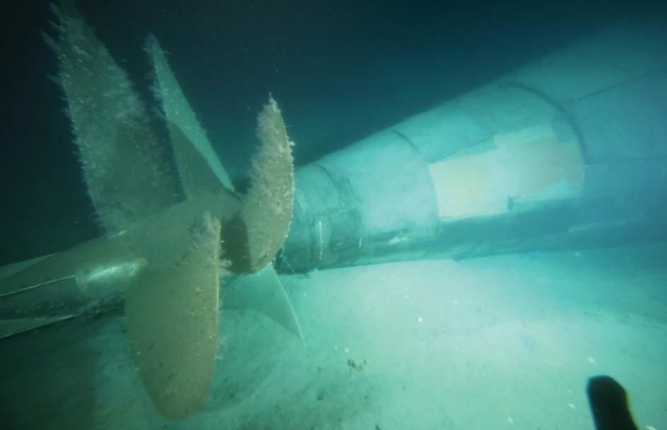
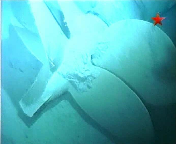

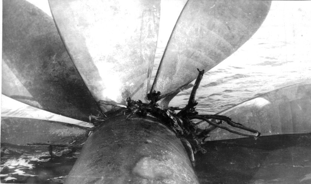 Perhaps your Victor 3 episode is what this picture is all about, although after the fact.
Comment