

I hate going first. Sorry about the posting in the wrong area MR "C"
-
-
Here we go, looks like I will be the first to have a go.
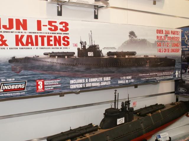
When Lindberg announced the release of there two 1/72 scale subs I thought all of my Christmas's had come at once. Being an Australian and borne in Sydney just after the war I have always had a special interest in the Jap subs that raided Sydney harbor. So I just had to have a model of the sub that carried the 2 man mini subs that managed to beat the harbor defenses and fire two torpedo's sinking one ship. After much waiting and a lot of disappointment in what was actually being released I placed an order with Mike at Caswell and sat back waiting for it to arrive. What found in the transport box was akin to finding out there is no Santa. That as we all know now looked good on paper but was a big let down in real life. Apart from the model itself I was also having trouble finding any good information on ANY IJN sub but after a lot of digging I found enough to get started.
This is what I had to work with
-

The plastic kit that Lindberg produced is a bit of a challenge, seems like they BLENDED 3 or 4 IJN subs together and then added what they thought would be COOL on there new model. Makes one wonder what they have in there water cooler. I soon realized that there was no way with my very limited skills to turn this thing into a C1 class sub like I wanted to. What can a man do?. Being Australian and having "GIVE IT A GO" drummed into me from an early age I started to look at what other possibilities this heap of junk could be turned into. At first, information on any IJN was hard to come by but after a lot of looking and asking I started to build a good reference base on what I might be able to build. The info came in very slow to start with but after a while the quality and quantity started to build to a point where I could at last make a decision on what type of boat I could turn this heap of plastic into.
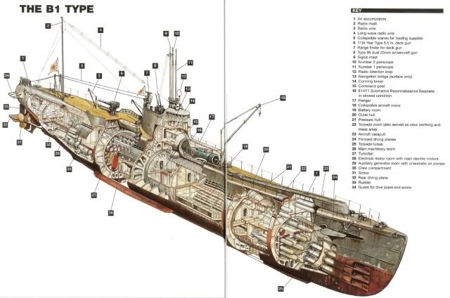
The boat that was going to be the easiest to convert the Lindberg thing into was a IJN B1 class, But the big question was which one?
Comment
-
I have found a B1 that I think would be a good boat to model, It is the B1 type I-25 and its Skipper was Lieutenant Commander Meiji Tagami.
http://subart.net/tagami.htm It seems like he was at every big event from Pearl Harbor, Sydney, Melbourne, Pacific islands and even bombed the good old USA mainland. http://www.combinedfleet.com/I-25.htm He and the boat didn't make it to the end but few did.
So with the prototype found to base the build on, a good history of its movements all that is left is to find some photos of the I-25 and start working on getting the Lindberg thing to look the way I want it to. Let the games begin.Comment
-
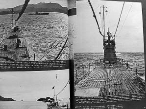
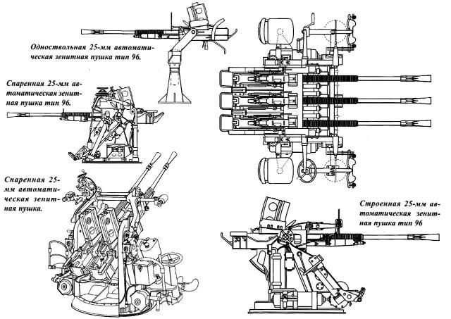
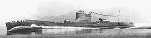
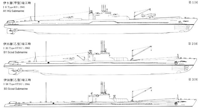
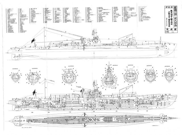
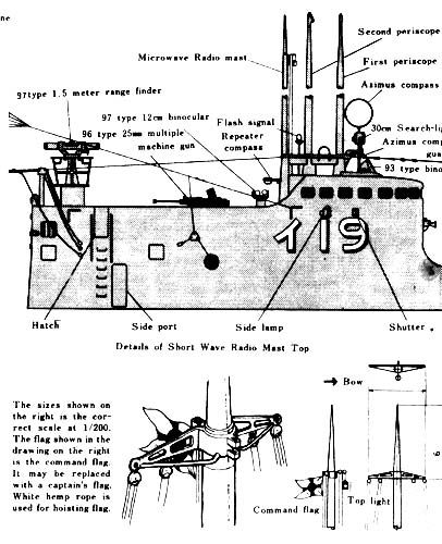
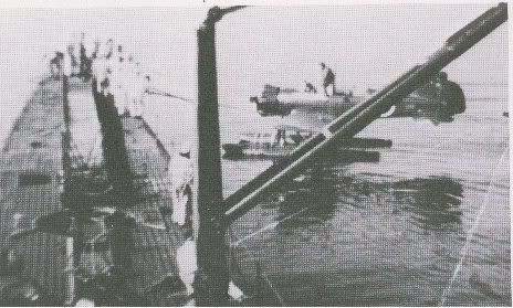
Here is some of the information I am using as a guide for this build. Looks like it is going to be a fun build.
NOW where did I put my dermal?Comment
-
On with the build. The quality of the plastic and the fit of parts in this huge kit is very good. The hull has quite thick plastic and is supplied in 4 pieces. The instructions only tell you how to build the Lindberg "THING" and as such are not much use other than a basic guide on how it is assembled.
The first thing I did was join all the hull parts together to see what I had to work with. It was big, gray, and if I closed one eye and squinted with the other one I could just see a real boat hiding in there. While it was sitting there I went from the bow to the Stern and made a list of thing that needed to be adjusted and there was a lot of them.
The first thing that needed adjusting to convert this thing into RC was the control surfaces, then the drive shafts and last but not least the pointy bit at the front of the boat.
I started with the easy bit first. the prop shafts. I used 1/8 brass rod for the shafts and 1/8+ id brass K&S tube for the bearings through the hull and in the skegs. Using the kit parts of the rear dive planes a few photos and the kit prop shafts I was able to line up and drill the holes and install the tubes with little or no problems.
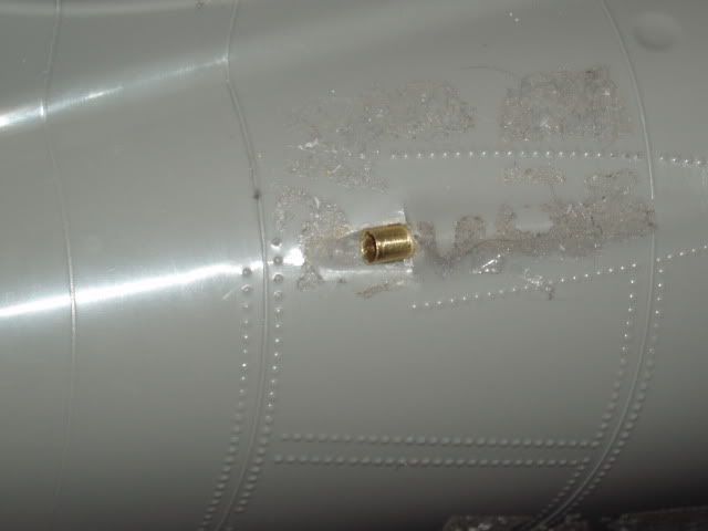
So far so goodComment
-
Following this thread with great interest! I have a 1/48 Scale Shipyards B Class boat that I'll get to one day!Comment
-
Yes! Good presentation so far. I too am interested in how you're going to r/c this beast. Eventually I'm going to do the same. If things slack off a bit around here I would like to finish that bow master for the thing.
David,Who is John Galt?Comment
-
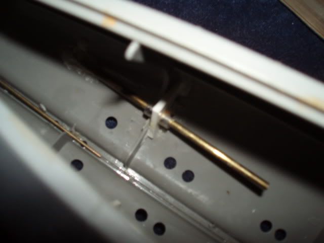
Once the bearings were lined up they were set in place with some 24hour Araldite on the inside of the 2 rear hull pieces. A thrust support plate was made to support the for and aft thrust loads on both prop shafts and they are held in place with 4, 2 each side 1/8" model aircraft wheel adapters. The idea of the thrust plate is to take any loading that might be placed on the shaft and transfer it to the hull instead of the drive line. Sorry about the photo (not enough light, old camera)
Comment
-
Count me as well as being an interested spectator. I, too, was planning to do a B-type with one of their kits but now just sitting it out hoping they do release the other kit.Comment
-
Don't worry "herrmill" they will now. I have found over the years of modeling as I am certain some of you have also found, that as soon as I build a conversion some one will release a kit of the same thing but better. Why should things change now?Comment
-
Back to the build. I guess I should mention my goals for this build/conversion.
1: It should look like a WWII Japanese B1 type sub or as close as I can get it.
2: It should look as good in the water as well as out of the water.
3: Run as good if not better than the original, both surfaced and submerged.
4: Must dive as well as surface as quick as the original.
5: Must have at least 2 safety devices. a: fail safe ballast blow b: fail safe recovery float chamber with lights.
6: Be easy to build with only hand tools.
7: Be Super reliable and dry
8: Long run times
9: BE FUN TO RUN AND BUILD, If it ain't fun it don't get done.
10: What ever else I can think would be good or whatever you can add to help.Comment
-
Being happy with the way the prop shafts turned out it is now time to look at the control surfaces.
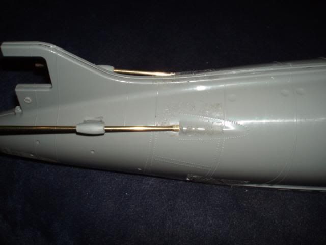
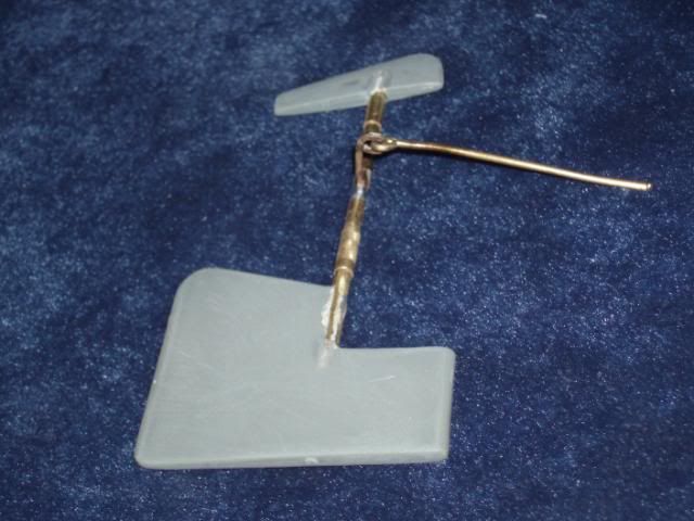
The 2 piece rudder was easy, all I needed was a piece of 1/8 brass rod and some K&S tube to fit over the rod to act as bearings. The lever point was made using some 1/16" rod soldered to the 1/8" rod and bent to shape
Using the kit parts I carefully drilled both parts of the rudder to accept the 1/8" rod. Cut the rod to the correct length slid the 2 bearings over the rod and then pressed the parts together lined it all up and fixed it to stop any movement on the rod.
The next part of the operation was to enlarge the mounting holes in the 2 rear hull half's to accept the bearings of the rudder shaft. I dry assembled the rear hull half's with the new rudder in place to check for any binding and alignment issues.
This is what it looks like now
Comment
-
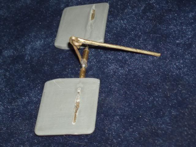
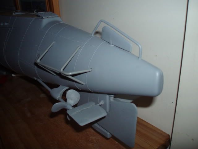
The next parts to receive attention are the rear dive planes.
First thing I had to do was make enough room inside the 2 rear hull sides to accommodate the linkages. The work went easy and fast using a dremmel because not much had to be removed from the inside surfaces to give me enough room for the linkages to move freely and with out any binding over the range of movement. When converting the kit parts to workable RC parts I used 1/16" K&S rod, cut to the correct length and bent and soldered together, then I just drilled a hole into each of the kit dive planes just a bit smaller than 1/16" and pressed the planes onto the shafts but not before making and installing some mounting bearings from some K&S tubing.
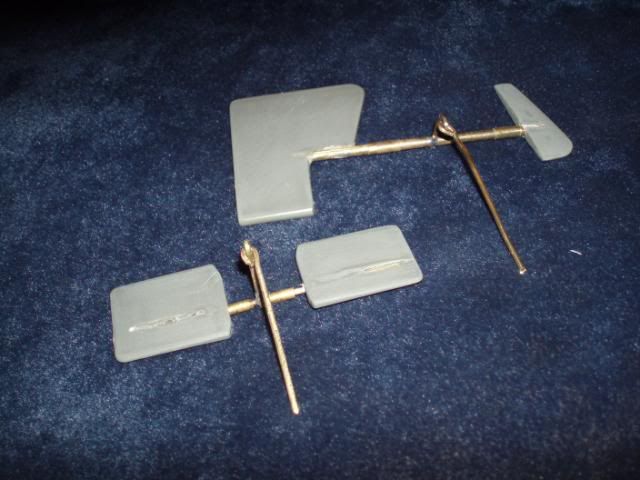
The next step was to drill out the mounting points to accept the new size shaft bearings and do a dry test fit. All went well and again a fairly easy conversion so far.
I did find it easier to mount the dive planes to the shafts after the linkage was installed into the hull.
The kit rear dive planes are not the correct size or shape but that will be resolved later on down the build. At the moment I just want to see if it can be done and without much effort.
So far so goodComment
-
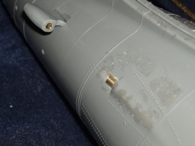
This will give you an idea of what it will look like.
Comment


Comment