Tool time.

Collapse
X
 
  • Time
  • Show
Clear All
new posts
  • Davidh
    Captain
    • Nov 2010
    • 719

    #61
    Thanks lads,

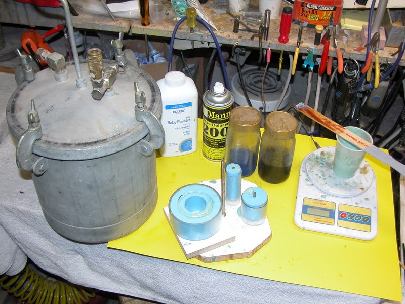
    I mix up the MEKP and resin first , then add the talc. The talc is recent. As subculture mentioned I should try some of this silica or even an epoxy gel coat. Any other ideas?


    David H

    Comment

    • Subculture
      Admiral
      • Feb 2009
      • 2119

      #62
      Another method i have seen used is to mix some polyester bodyfiller/putty with resin to thin it down a bit, and use that in place of gelcoat. Haven't tried this personally, I believe that bodyfiller is mainly talc and resin, but they probably stick some other stuff in as well to make it a bit lighter and more elastic- manufacturers don't tend to make public their blends.

      Comment

      • trout
        Admiral
        • Jul 2011
        • 3545

        #63
        I would add, make sure your mixing well......Change cups was a tip I got from a demo by Smooth-On. the idea is the sides and areas around the cup surfaces may not get completely mixed even with the best intentions, but pouring the mixture to a new cup eliminates that. Test on small area first. A whole hull can add up in cost, but a bust of David Merriman would be small (or some other subject). I know these are common solutions and I am sure you know these things.....just going back to basics helps me.
        If you can cut, drill, saw, hit things and swear a lot, you're well on the way to building a working model sub.

        Comment

        • Scott T
          Commander
          • May 2009
          • 378

          #64
          Is there anyway to cure the gooey spots like vacuum bag it; or is it done catalyzing?
          I read " I poured some of the hardener onto the brush and painted it onto the sticky soft spots and applied some heat from the pistol hair dryer. "
          Last edited by Scott T; 03-09-2018, 02:01 PM. Reason: added something I had read

          Comment

          • Davidh
            Captain
            • Nov 2010
            • 719

            #65
            Hello all,

            Some questions for HWSNBN,

            I am thinking of redesigning my twin shaft endcap for the Project 661 and so have been looking over lots of your work. I was particularly interested in the series of photos on the most recent Albacore build of Scott’s. You show the assembly of a twin endcap. The photos don’t show how the shaft extension is fixed to the shorter motor shaft. I was really surprised that you only secure the cone shaped seal housing with silicon right over the top of the motor mount bolts?. I am assuming this is strong enough? I have always thought of bolting these extensions onto the main endcap.


            Judging by your design the only support of the shaft has after leaving the front bearing of the motor is the seal. Is this correct? I always produced a ‘tunnel’ for the shaft in between the seal and the motor to reduce any water ingress, usually with a tunnel barely bigger than the diameter of the shaft. This has meant that the shaft has had to be dead center or runs the risk of rubbing up against the tunnel, causing heat and more load on the motor. It would seem with your set up that the shaft extension could run with some slop as there is more gap? This being absorbed by the flexing lip of the seal? ( yes I know, you don’t do slop)

            I know now you wouldn’t keep this design in production if it didn’t work. I know you shafts don’t leak. I’ve got one of your Subdrivers in the Mike. So I can assume that you place great faith in that seal.. judging from all this I could probably get away with less engineering in my design.

            I hope these questions make sense.


            I look forward to your guidance.

            David H.


            Last edited by Davidh; 04-15-2019, 05:56 AM. Reason: Photo won’t upload!!

            Comment

            • Davidh
              Captain
              • Nov 2010
              • 719

              #66
              Click image for larger version

Name:	E3B4D16B-F33C-4E7E-8C5B-969D82C92937.jpeg
Views:	236
Size:	202.6 KB
ID:	131759

              The photo of the twin motor mount arrangement.


              Comment

              • Davidh
                Captain
                • Nov 2010
                • 719

                #67
                Anybody, please?

                Comment

                • He Who Shall Not Be Named
                  Moderator
                  • Aug 2008
                  • 12256

                  #68
                  Originally posted by Davidh
                  Anybody, please?
                  I'm on it. I'm collating now and will put it down in the next couple of days.

                  David
                  Who is John Galt?

                  Comment

                  • Davidh
                    Captain
                    • Nov 2010
                    • 719

                    #69
                    Thank you David. Much appreciated...

                    dave

                    Comment

                    • He Who Shall Not Be Named
                      Moderator
                      • Aug 2008
                      • 12256

                      #70
                      Originally posted by Davidh
                      Hello all,

                      Some questions for HWSNBN,

                      I am thinking of redesigning my twin shaft endcap for the Project 661 and so have been looking over lots of your work. I was particularly interested in the series of photos on the most recent Albacore build of Scott’s. You show the assembly of a twin endcap. The photos don’t show how the shaft extension is fixed to the shorter motor shaft. I was really surprised that you only secure the cone shaped seal housing with silicon right over the top of the motor mount bolts?. I am assuming this is strong enough? I have always thought of bolting these extensions onto the main endcap.

                      Judging by your design the only support of the shaft has after leaving the front bearing of the motor is the seal. Is this correct? I always produced a ‘tunnel’ for the shaft in between the seal and the motor to reduce any water ingress, usually with a tunnel barely bigger than the diameter of the shaft. This has meant that the shaft has had to be dead center or runs the risk of rubbing up against the tunnel, causing heat and more load on the motor. It would seem with your set up that the shaft extension could run with some slop as there is more gap? This being absorbed by the flexing lip of the seal? ( yes I know, you don’t do slop)

                      I know now you wouldn’t keep this design in production if it didn’t work. I know you shafts don’t leak. I’ve got one of your Subdrivers in the Mike. So I can assume that you place great faith in that seal.. judging from all this I could probably get away with less engineering in my design.

                      I hope these questions make sense.


                      I look forward to your guidance.

                      David H.
                      I always present the SD drive-shaft with a journal-bearing where is projects from the SD proper. It's not apparent in the shots of the small 2" diameter SD used for the 1/96 ALBACORE, but there is an Oilite bearing tucked in right behind the cup type watertight seal. A cut-away of that bearing-cup assembly presented here:


                      The design of the bearing-seal assembly originates with Skip Assay. Note that the bearing-seal body is either brass or resin.


                      Note that the bearing is there to take the lateral, side-to-side shaft loads and not to take any axial or thrust load. In direct drive motors I outfit the motor with an extension, or intermediate drive shaft. That shaft running straight from the motor to the bearing-seal unit set within a resin bearing-seal foundation that is affixed to the wet side face of the motor bulkhead. Note the use of air-dry RTV adhesive to secure these parts together. Any otherwise harmful vibrations are damped out by the flexibility of the assembly.


                      Point of interest: on those drive-trains where I introduce a gear-train between motor and drive-shaft, there are three journal bearings: one set in the motor-bulkhead end-plate (that mounts the motor); another bearing set within the motor-bulkhead body; and the third bearing part of the bearing-seal unit. The two forward bearings are there to handle the high lateral force produced by the driving pinion gear against the driven spur gear.


                      It's my practice to isolate the SD drive-train from all thrust loads presented by the propulsor. Those loads applied to a proper thrust bearing at the base of the propeller hub (ahead load) and forward face of the universal coupler attached to the forward end of the propeller shaft (astern load).

                      David


                      Who is John Galt?

                      Comment

                      • Davidh
                        Captain
                        • Nov 2010
                        • 719

                        #71
                        Click image for larger version

Name:	9B16024B-BC79-4436-B617-234A6A1AFB2E.jpeg
Views:	180
Size:	9.5 KB
ID:	131809Click image for larger version

Name:	A2752417-4066-4FF4-A4E7-A3DDCDD60F9B.jpeg
Views:	194
Size:	10.6 KB
ID:	131807Click image for larger version

Name:	8011829B-BF48-4301-BD81-8CC7FC425D3E.jpeg
Views:	187
Size:	9.4 KB
ID:	131808
                        Thank you David. Photos are fantastic.

                        just a couple of questions.

                        How do you secure the extension drive shaft? I can see that a hole has been drilled for the motor shaft to slot in. Do you glue it or tap friction fit it in?

                        So so on this design, the front of the housing secures the lip seal in place and is held by RTV silicon. Dark section at joint is one of the blue lip seals. Once I peel back the paper from the front face of the outer end cap I will drill the motor mount holes, mount motor and push assembly onto motor shaft, (flats ground on motor shaft) and silicon around it.

                        So so far so good.

                        thanks once again David.

                        david h


                        Comment

                        • trout
                          Admiral
                          • Jul 2011
                          • 3545

                          #72
                          I hope this will make sense, but you have enough material on your cone that you could put a flat spot or step in it that a nut and washer can secure it down.
                          If you can cut, drill, saw, hit things and swear a lot, you're well on the way to building a working model sub.

                          Comment

                          • He Who Shall Not Be Named
                            Moderator
                            • Aug 2008
                            • 12256

                            #73
                            Originally posted by Davidh
                            Hi Dave, and anyone else who wants to contribute,..

                            After building Resolution and doing a lot of looking into silicon RTV moulds I have finally dived in the deep end and use RTV as I have wanted to do castings of hydroplanes etc..

                            i have looked very carefully at all the pics you've put up of your green and Blue Rtv moulds as well as Youtube and have started doing similar for the Resolutions control surfaces. I haven't done the whole spruce and vent set up yet, want to get experience just with the basic castings.

                            I get the impression from your workshop that silicon moulds are probably the most common form of tooling that you develop for fabricating parts, is this right? Do you still use hard shell (grp) moulds for hulls? I would consider using silicon moulds for larger parts if they give better fidelity but just don't know enough about how wobbly a large mould like that would be and making sure it was supported enough.

                            what kind of lifecycle do you get out of your silicon moulds? Any particular hints in looking after them or specific things I should keep an eye on whilst making them and or using them?

                            i see that these moulds are really wobbly. You back them with what looks like a piece of chipboard. Is there the concern that you may have a little give in the silicon mould and it may slightly distort the piece coming out of it?

                            Out of curiosity you must have made hundreds of these moulds, would that be correct?

                            the skills you freely impart are fantastic, I just wonder whether more discussion about tooling design and use would complement the other skills that you teach. I would certainly find it beneficial.

                            thanks Dave,


                            David H
                            OK, I'm finally getting around to giving you some useful information, with specific answers to your questions. And some added dope thrown in for good measure.

                            For large tools, specifically those used to give form to GRP hull parts, I almost exclusively construct glove-mother molds. An inner rubber 'glove that defines the shape and details of the eventual parts surface; and an outer 'mother' mold to support and render ridged the glove mold.


                            On occasion I will go with a glove-mother mold type tool to render cast resin parts, such as this hollow tail-cone for our 1/60 ALBACORE kit.


                            Yes, almost all my cast resin, and metal parts are formed within silicon, room temperature curing (RTV) mold making rubber. Today I get my rubber from this source: https://bjbenterprises.com/index.php/silicones/

                            The TC-5050 for resin casting and metal casting. I use their 'brushable' rubber, TC-5040, for glove molds.

                            As to the rubber tools utility: I have a metal casting tool that was new nearly 30 years ago, and it's still cooking! Today, using Mann mold/part release spray and a powdering with talc I get about 100 shots out of a typical tool before its trashed.

                            Yeah, I've built hundreds of tools for resin and metal casting. There's nobody on this planet better at this game than me.

                            Basic resin casting: It's one thing to introduce resin into the cavities of the mold (the specifics of tool design with all the sprue, vent, and header specifics outlined later), its another to insure all air previously occupying those cavities is displaced completely by the resin. There are four methods of introducing the resin in such a manner as to encourage a complete fill of the tools cavities.

                            First, is the simple pouring of catalyzed resin into the sprue of the tool and letting gravity do its work. If the resin is fresh, the tool is properly designed, the cavities are of simple geometry and of substantial cross-section, and the correct part-release agents are applied to the face of the flanges and cavities, then this is technique is good enough to achieve well formed parts.


                            Second, is for tools with cavities of relatively small cross-section, and moderate complexity of geometry. This is pressure casting. Where the filled tool is placed into a pressure pot and subjected to at least one atmosphere of pressure (one Bar, or 15psig, or 30psia). What little bubbles may still displace resin within the cavity are crushed back into the resin solution, insuring a 'pin-hole' free cast part.


                            Who is John Galt?

                            Comment

                            • He Who Shall Not Be Named
                              Moderator
                              • Aug 2008
                              • 12256

                              #74
                              The pressure pot can take the form of a commercially available 'paint pot', such as these here:


                              Or custom made pressure pots for larger tools. Like these:


                              Third, is centrifugal resin casting. Resin is introduced into a spinning tool through a central sprue. From the sprue the liquid resin is channel outboard toward the circumference of the tool. Great force is applied with this technique insuring complete displacement of air and perfect resin parts achieved.


                              And forth, is vacuum assisted resin casting. Ideal for the most complex of cavity shapes and narrowest of cross-sections. Only a very small sprue is provided each cavity, each sprue hole sharing a common trough. Resin is mixed up, poured into the trough, and the tool subjected to a hard-vacuum. The work is returned to atmospheric pressure before the resin changes state, and is left to cure out.


                              Who is John Galt?

                              Comment

                              • He Who Shall Not Be Named
                                Moderator
                                • Aug 2008
                                • 12256

                                #75
                                Now, to the specifics of rubber tool design. The objective is to insure a quick and complete fill of the tool cavities. I've covered the unique features of centrifugal and vacuum type tools. What I'm describing now is the more traditional gravity and pressure assisted type tools. Looking at a typical set of cast resin parts, still attached to their sprue and vent channel network, pretty much informs you how the introduced liquid resin displaces air as the cavities fill:


                                The big central sprue, and auxiliary sprues if used, are typically formed as the tool halves are poured over the masters.


                                The vent channels are cut in after the tool halves are formed. Like so:


                                However, when the eventual tool cavity is of significant cross section, and long enough, I will press the cavity itself into service as the main sprue. Which is the situation with the two tool masters on the left:


                                David
                                Who is John Galt?

                                Comment

                                Working...