
Assorted names I came up for this item.
Servo Splitter (SS)
Servo Signal Splitter (SSS)
Shared Servo Signal Connector (SSSC)
Shared Servo Connector (SSC)
Shared Servo Signal PCB (SSSP)
Shared Servo PCB (SSP)
What is a Servo Splitter?
A Servo Splitter is equivalent to a servo y-cable. With limited space in 2.5 or 3.5 inch cylinders, you can save space and eliminate trying to tie up the bulky servo y-cable with this component. It also gives you a much cleaner appearance. In a model submarine, this connector is usually used to share the receiver signal between the ballast vent servo and the ballast tank pump. Alternatively, it can be used to run two servos from one channel. As an example, in a surface boat, two servos operating individual rudders in a twin rudder model. (But who would do that?)
Bob did a nice video explaining this device.
What is needed?
With a few components purchased from Amazon, you can make one, or a few, for yourself. It is more efficient to make more than one of these as you probably have more than enough material and it will save time making more at the same time than making another batch later.
https://www.amazon.com/Prototype-Perfboard-Breadboard-Electronic-Experiments/dp/B09BCT2T8W/ref=sr_1_8?asc_campaign=2f23b78db3f82fce1ed7eb172f 790c32&asc_source=01H6VFNRNQPGR11APMPAW4YJ3J&crid= 2WCJK1BHU1EFG&keywords=pcb+single+perf+board&qid=1 697644511&sprefix=pcb+single+perf+board%2Caps%2C85 &sr=8-8&tag=namespacebran629-20
Header
https://www.amazon.com/dp/B09MYBRW3F?psc=1&ref=ppx_yo2ov_dt_b_product_detail s
Male to male servo cable
https://www.amazon.com/DIYmall-10PCS-Servo-Extension-Cable/dp/B016RJ8S42/ref=sr_1_5?crid=3VY1PXI2O3XW&keywords=male+to+male +servo+cable&qid=1700751710&sprefix=male+to+male+s ervo+cable%2Caps%2C94&sr=8-5
Size comparison.

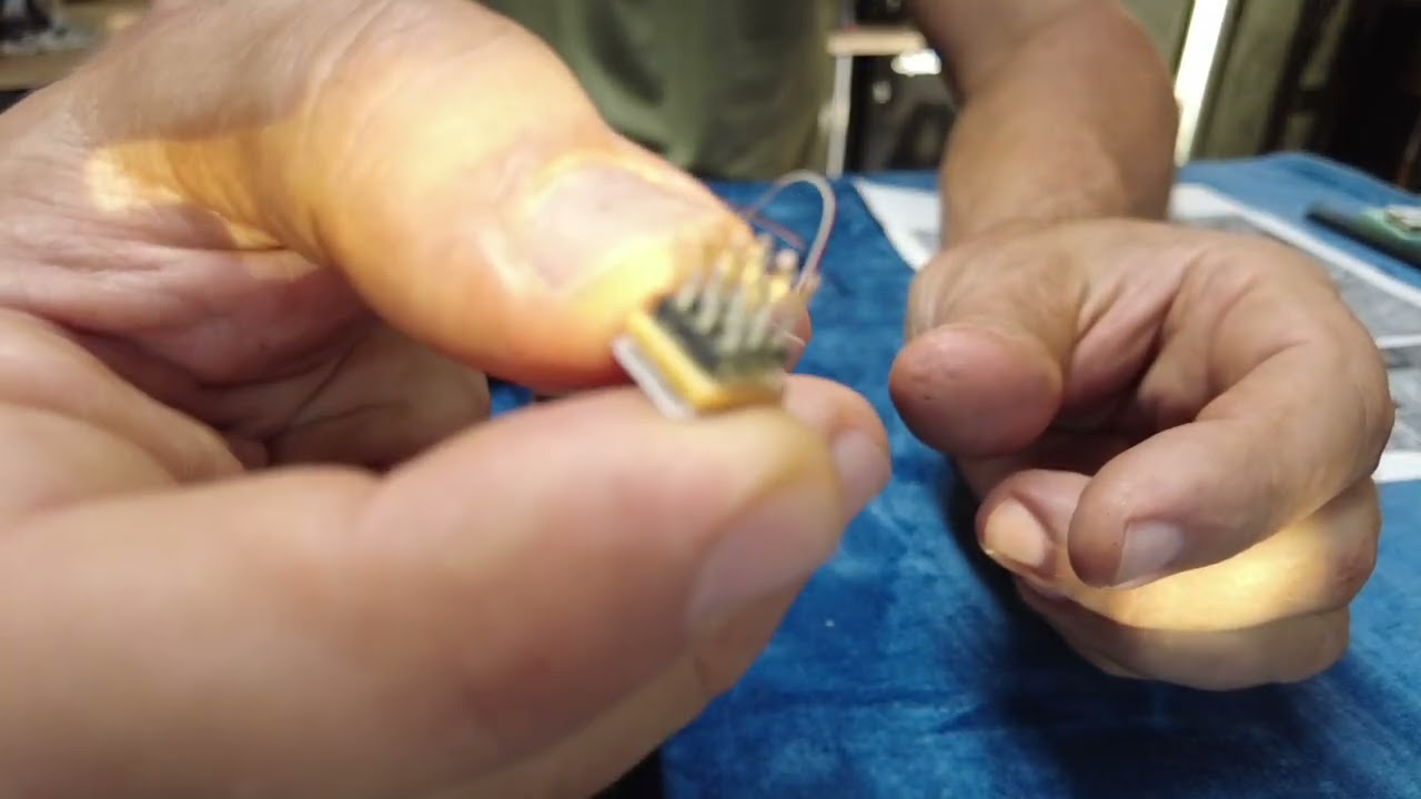
Finished product. The soldered side of the PCB is protected by epoxy and a piece of styrene. The line indicates the direction the servo cables need to be plugged in.

The PCB and header connectors.

For this demonstration I will be using a PCB I had on hand. Note there are sections where there are rows for three pins for the headers.

With a pair of cutters, cut off three sets of pins with three pins in each set.

You can solder the header pins to the uncut PCB and cut the PCB later or you can cut the PCB and solder the pins to it. I elected to cut the board and solder after.
With either method, you will have to leave a space between the set of pins to cut the board. The pins will require a 3x3 matrix and one row between them for cutting.

Here you can see the area that will be cut.

The PCB's have been cut and pins ready for insertion. At this point use a file to clean up the board edges, removing any burrs and squaring up the edges to each other. You may want to insert a header in each direction and get the width of the board filed down to the edge on the plastic of the header.

The headers are inserted into the PCB, flipped over and the longer ends are inserted into another PCB. This will keep the pins aligned in the 3x3 matrix so all of the pins keep the 1/10th distance required for the servo connectors. For consistency I also insert the headers so that they are 90 degrees to the traces on the bottom of the board. This can be a visual for the direction to plug in the servo cables. I used a set of tweezers to steady the board for soldering. I also placed a weight on the tweezers to further steady the assembly.

Two soldered boards.

Using a Dremel stone to trim down the sharp points of the pins. This has been done for a future step. Also, I used electronics cleaner with a tooth brush to remove any solder flux and to remove any filings.

For the following steps, refer back to this picture. Rows need to be tested to be sure there are no shorts between rows. Pins 1,2,3 will have continuity. Pins 4,5,6 will have continuity. Pins 7,8,9 will have continuity. There will be no continuity between pins 1-4 and between 4-7.
When we are done. Row 123 will be the receiver ground or servo signal, row 456 will be five volts, row 789 will be servo signal or ground depending how your cable is plugged in.

Connect a voltmeter to check for continuity and opens and determine orientation. Place leads on two corners. If you get no continuity, then you have pins 1 and 7. If you get continuity as in the below picture then you have pins 1 and 3.

Here there is an open, no continuity. So you have pins 1 and 7.
At this point place the probes on pins 1 and 4. There should be no continuity.
Place the probes on pins 4 and 7. There should be no continuity.
If there is continuity between either pins 1 and 4 or 4 and 7, check the solder side of the board for solder that may have strayed between any of the rows and resolve the issue until there is no continuity between the rows.

Once the boards have been soldered and tested, get a non-metallic backing material. I used 20 thousandths styrene, sanded on one side. I mixed a small batch of epoxy resin. Dipped the soldered side of the PCB in the resin multiple times to get the bottom of the board coated with the resin. Place it on the sanded styrene and let it set. Placing a weight on the pins will be sure it is not floating on the resin.

Cut the styrene and file the edges down to the edge of the PCB. I also rounded the corners and edges of the styrene so there is no chance of catching on anything. Make it look nice.

Use the voltmeter and find row 123. Flip it over. I plugged my splitters into a breadboard to keep them steady. Do what you can to hold them still.

Draw a line on the styrene which will be 90 degrees to row 123. When the servo cables are plugged in, they should be plugged in in the direction of this line. If you oriented the headers 90 degrees to the traces on the bottom of the PCB, the servo cables can be plugged in inline to the headers. Although the separation between the headers may be difficult to see. The servo cables can be plugged in with the signal cable connected to row 123 or row 789.
WARNING. If you do not plug the servo cable in the correct way, then you will be shorting out the ground, 5 volt and signal cables on the receiver. Plugging a cable into pins 123 is incorrect.

Example of two servos cables and a cable from the receiver plugged into the splitter. Note the signal cables are all on the same side.

The same setup flipped over showing the ground side of the cables.

Here is a bench example of two servos connected to a receiver with a y-cable. The y-cable I have on hand is quite long.

Same setup with y-cable removed and the Servo Splitter cable in place.

If you have limited space on your receiver for your BEC or battery, here is an alternative. Add a fourth row of pins on the PCB. When you cut the PCB, just be sure to add the additional rows in line as shown below. When plugging in the cables, be sure the ground wire for the battery is in line with the ground wire on the servo cables. The unused pin on the battery cable will be in line with the signal cables.

Servo Splitter (SS)
Servo Signal Splitter (SSS)
Shared Servo Signal Connector (SSSC)
Shared Servo Connector (SSC)
Shared Servo Signal PCB (SSSP)
Shared Servo PCB (SSP)
What is a Servo Splitter?
A Servo Splitter is equivalent to a servo y-cable. With limited space in 2.5 or 3.5 inch cylinders, you can save space and eliminate trying to tie up the bulky servo y-cable with this component. It also gives you a much cleaner appearance. In a model submarine, this connector is usually used to share the receiver signal between the ballast vent servo and the ballast tank pump. Alternatively, it can be used to run two servos from one channel. As an example, in a surface boat, two servos operating individual rudders in a twin rudder model. (But who would do that?)
Bob did a nice video explaining this device.
What is needed?
With a few components purchased from Amazon, you can make one, or a few, for yourself. It is more efficient to make more than one of these as you probably have more than enough material and it will save time making more at the same time than making another batch later.
- It consists of a perf type PCB with copper traces on one side. The other side can be blank or have traces on it, it does not matter. As there are many types of this board, you need the side with traces to have either a continuous strip or at least groups of three together.
- Another item is a header pin strip.
- To connect this connector to the receiver you will also need a male to male servo cable.
https://www.amazon.com/Prototype-Perfboard-Breadboard-Electronic-Experiments/dp/B09BCT2T8W/ref=sr_1_8?asc_campaign=2f23b78db3f82fce1ed7eb172f 790c32&asc_source=01H6VFNRNQPGR11APMPAW4YJ3J&crid= 2WCJK1BHU1EFG&keywords=pcb+single+perf+board&qid=1 697644511&sprefix=pcb+single+perf+board%2Caps%2C85 &sr=8-8&tag=namespacebran629-20
Header
https://www.amazon.com/dp/B09MYBRW3F?psc=1&ref=ppx_yo2ov_dt_b_product_detail s
Male to male servo cable
https://www.amazon.com/DIYmall-10PCS-Servo-Extension-Cable/dp/B016RJ8S42/ref=sr_1_5?crid=3VY1PXI2O3XW&keywords=male+to+male +servo+cable&qid=1700751710&sprefix=male+to+male+s ervo+cable%2Caps%2C94&sr=8-5
Size comparison.
Finished product. The soldered side of the PCB is protected by epoxy and a piece of styrene. The line indicates the direction the servo cables need to be plugged in.
The PCB and header connectors.
For this demonstration I will be using a PCB I had on hand. Note there are sections where there are rows for three pins for the headers.
With a pair of cutters, cut off three sets of pins with three pins in each set.
You can solder the header pins to the uncut PCB and cut the PCB later or you can cut the PCB and solder the pins to it. I elected to cut the board and solder after.
With either method, you will have to leave a space between the set of pins to cut the board. The pins will require a 3x3 matrix and one row between them for cutting.
Here you can see the area that will be cut.
The PCB's have been cut and pins ready for insertion. At this point use a file to clean up the board edges, removing any burrs and squaring up the edges to each other. You may want to insert a header in each direction and get the width of the board filed down to the edge on the plastic of the header.
The headers are inserted into the PCB, flipped over and the longer ends are inserted into another PCB. This will keep the pins aligned in the 3x3 matrix so all of the pins keep the 1/10th distance required for the servo connectors. For consistency I also insert the headers so that they are 90 degrees to the traces on the bottom of the board. This can be a visual for the direction to plug in the servo cables. I used a set of tweezers to steady the board for soldering. I also placed a weight on the tweezers to further steady the assembly.
Two soldered boards.
Using a Dremel stone to trim down the sharp points of the pins. This has been done for a future step. Also, I used electronics cleaner with a tooth brush to remove any solder flux and to remove any filings.
For the following steps, refer back to this picture. Rows need to be tested to be sure there are no shorts between rows. Pins 1,2,3 will have continuity. Pins 4,5,6 will have continuity. Pins 7,8,9 will have continuity. There will be no continuity between pins 1-4 and between 4-7.
When we are done. Row 123 will be the receiver ground or servo signal, row 456 will be five volts, row 789 will be servo signal or ground depending how your cable is plugged in.
Connect a voltmeter to check for continuity and opens and determine orientation. Place leads on two corners. If you get no continuity, then you have pins 1 and 7. If you get continuity as in the below picture then you have pins 1 and 3.
Here there is an open, no continuity. So you have pins 1 and 7.
At this point place the probes on pins 1 and 4. There should be no continuity.
Place the probes on pins 4 and 7. There should be no continuity.
If there is continuity between either pins 1 and 4 or 4 and 7, check the solder side of the board for solder that may have strayed between any of the rows and resolve the issue until there is no continuity between the rows.
Once the boards have been soldered and tested, get a non-metallic backing material. I used 20 thousandths styrene, sanded on one side. I mixed a small batch of epoxy resin. Dipped the soldered side of the PCB in the resin multiple times to get the bottom of the board coated with the resin. Place it on the sanded styrene and let it set. Placing a weight on the pins will be sure it is not floating on the resin.
Cut the styrene and file the edges down to the edge of the PCB. I also rounded the corners and edges of the styrene so there is no chance of catching on anything. Make it look nice.
Use the voltmeter and find row 123. Flip it over. I plugged my splitters into a breadboard to keep them steady. Do what you can to hold them still.
Draw a line on the styrene which will be 90 degrees to row 123. When the servo cables are plugged in, they should be plugged in in the direction of this line. If you oriented the headers 90 degrees to the traces on the bottom of the PCB, the servo cables can be plugged in inline to the headers. Although the separation between the headers may be difficult to see. The servo cables can be plugged in with the signal cable connected to row 123 or row 789.
WARNING. If you do not plug the servo cable in the correct way, then you will be shorting out the ground, 5 volt and signal cables on the receiver. Plugging a cable into pins 123 is incorrect.
Example of two servos cables and a cable from the receiver plugged into the splitter. Note the signal cables are all on the same side.
The same setup flipped over showing the ground side of the cables.
Here is a bench example of two servos connected to a receiver with a y-cable. The y-cable I have on hand is quite long.
Same setup with y-cable removed and the Servo Splitter cable in place.
If you have limited space on your receiver for your BEC or battery, here is an alternative. Add a fourth row of pins on the PCB. When you cut the PCB, just be sure to add the additional rows in line as shown below. When plugging in the cables, be sure the ground wire for the battery is in line with the ground wire on the servo cables. The unused pin on the battery cable will be in line with the signal cables.
Attached Files


Comment