
Been in RC a while - cars.
Decided to try something different, a submarine, a different submarine, cross between a jet fighter and a sub.
This started as a doodle, then several iterations to get the body shape then fill in the blanks - all the internals.
Along the way have revised the body several times for little tweaks - length to hold components, tail shroud adjusting ratios of inlet/outlet, how to steer, etc...
First test of the drive (prop) results were unexpected - the tapered tail shroud is enough of a drop that in addition to flow thru had considerable backwash coming from the inlet. Several prop configurations were tested all with more of the same results. Finally came up with a working solution - archimedes screw pump configuration.
Next came the ballast pump - again doing something different using a brushless motor outside the WTC. a few iterations again - smaller motor, cheaper motor, better print material etc....
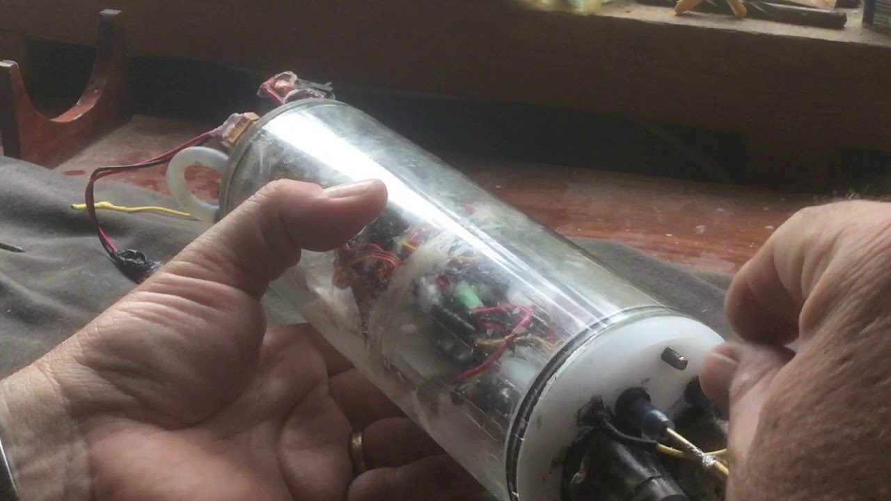
All that brings me up to this week, testing integration of the ballast tank and peristaltic pump. First test had its pros and cons. Pro - filled the ballast tank in about 15 seconds. Con at about 80% filled starte leaking past the O-rings. Inspecting the leak path seems like the lead in chamfers for the O-rings were close enough to get movement on the o-rings at higher pressure. With that moved the seals farther in away from the lead in chamfer. Print assemble and test (again). Moving the seals worked - too good, now have water weeping thru the pieces.... so yet another issue to address. Eventually will figure all this out.
Decided to try something different, a submarine, a different submarine, cross between a jet fighter and a sub.
This started as a doodle, then several iterations to get the body shape then fill in the blanks - all the internals.
Along the way have revised the body several times for little tweaks - length to hold components, tail shroud adjusting ratios of inlet/outlet, how to steer, etc...
First test of the drive (prop) results were unexpected - the tapered tail shroud is enough of a drop that in addition to flow thru had considerable backwash coming from the inlet. Several prop configurations were tested all with more of the same results. Finally came up with a working solution - archimedes screw pump configuration.
Next came the ballast pump - again doing something different using a brushless motor outside the WTC. a few iterations again - smaller motor, cheaper motor, better print material etc....
All that brings me up to this week, testing integration of the ballast tank and peristaltic pump. First test had its pros and cons. Pro - filled the ballast tank in about 15 seconds. Con at about 80% filled starte leaking past the O-rings. Inspecting the leak path seems like the lead in chamfers for the O-rings were close enough to get movement on the o-rings at higher pressure. With that moved the seals farther in away from the lead in chamfer. Print assemble and test (again). Moving the seals worked - too good, now have water weeping thru the pieces.... so yet another issue to address. Eventually will figure all this out.
Attached Files


Comment