Replacement 1/96 Trafalgar Class Propulsor Rotor?

Collapse
X
 
  • Time
  • Show
Clear All
new posts
  • wlambing
    Commander
    • Nov 2020
    • 295

    Replacement 1/96 Trafalgar Class Propulsor Rotor?


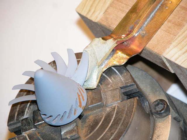
    Hi! I'm refurbishing a Small World Models 1/96 Trafalgar class I built 20+ years ago and recently re-acquired. I find I am in need of reconfiguring the propulsor shaft line to a longer shaft, as well as it being of 1/8" stainless rod vs. the original epoxy filled brass tube. The rotor itself is still serviceable, but the shaft is imbedded into the hub and is too short for stand-alone use as with the original WTC. I could try to remove the shaft, but the risk of destroying the rotor is great! Is there any source for said rotor, bored for a 1/8" shaft, either 3D printed or cast? Measured OD for the blades is ~1 33/64".

    Any thoughts or methods greatly appreciated!

    Take care,

    Bill​
    Last edited by wlambing; 05-05-2023, 10:21 AM.
  • He Who Shall Not Be Named
    Moderator
    • Aug 2008
    • 12338

    #2
    I'm making two assumptions, Bill: First, that you can pull the propeller shaft-rotor clear of the model; and that the rotor has been adhered to the shaft.

    If both conditions are met then you can break the shaft-rotor bond with heat.

    Wrap a very wet cloth around the rotor, and particularly around the after face of the rotor hub, but not touching the shaft. Two inches forward of the hub face apply a torch to heat the shaft. As the heat conducts aft to the hub, and into the bore of the hub, it will cause the glue to fail. Remove the rotor.

    Sing my praises! Notify the Press.

    David


    Last edited by He Who Shall Not Be Named; 05-05-2023, 10:48 AM.
    Who is John Galt?

    Comment

    • RCSubGuy
      Welcome to my underwater realm!
      • Aug 2009
      • 1777

      #3
      Or you could just fabricate a simple shaft coupler (1/8" to 1/8"?) and drop in an intermediary shaft to lengthen the original one.

      Comment

      • wlambing
        Commander
        • Nov 2020
        • 295

        #4
        Thanks to both of you for your responses! What I 'm hoping to do is exactly as illustrated in David's pictures. I don't know if heat would work as desired, as the rotor appears to have been cast with the brass tube shaft inserted in the mold. Think heat would break that grip? As for a 1/8" - 1/8" straight coupler, I 'spose I could. It's gonna take some finagling, for sure, as the hull still has all of the molded-in-place foundations for the original WTC in it. I'll have to see where I can mount that bearing supporting bulkhead. My original shaft stops about 1/4" forward of the tail cone's upper leading edge. The original u-joint screw was right below that edge. I shall get it! She now bears working stern planes, rudders and is graced with functional bow planes instead of the dummy planes she used to drive around with! I'm happy with the progress made in the past couple of days!

        I'll update after I figure something out.

        Take care,

        Bill

        Comment

        • He Who Shall Not Be Named
          Moderator
          • Aug 2008
          • 12338

          #5
          Originally posted by wlambing
          Thanks to both of you for your responses! What I 'm hoping to do is exactly as illustrated in David's pictures. I don't know if heat would work as desired, as the rotor appears to have been cast with the brass tube shaft inserted in the mold. Think heat would break that grip? As for a 1/8" - 1/8" straight coupler, I 'spose I could. It's gonna take some finagling, for sure, as the hull still has all of the molded-in-place foundations for the original WTC in it. I'll have to see where I can mount that bearing supporting bulkhead. My original shaft stops about 1/4" forward of the tail cone's upper leading edge. The original u-joint screw was right below that edge. I shall get it! She now bears working stern planes, rudders and is graced with functional bow planes instead of the dummy planes she used to drive around with! I'm happy with the progress made in the past couple of days!

          I'll update after I figure something out.

          Take care,

          Bill
          YUP................
          Who is John Galt?

          Comment

          • Subculture
            Admiral
            • Feb 2009
            • 2123

            #6
            Couple of years ago I drew a seventeen blade prop for Vanguard in Fusion 360.

            Basically a best guess based on jet engine fan blade geometry, and I dimensioned it to blend in with the original Prop shop supplied shroud on the OTW boat. I think proportionally the boss looks smaller than your Trafalgar.

            I crudely printed one out in PLA, no cleanup so a bit hairy as I had the temperature cranked up a bit high for that filament, but surprisingly strong. The endgame would be to have one cranked out in SLM aluminium or possibly 316L from a bureau.


            Click image for larger version

Name:	propulsor.jpg
Views:	134
Size:	50.7 KB
ID:	171013Click image for larger version

Name:	IMG_0987.jpg
Views:	131
Size:	68.4 KB
ID:	171015
            Attached Files

            Comment

            • He Who Shall Not Be Named
              Moderator
              • Aug 2008
              • 12338

              #7
              Work I did to improve the 1/100 OTW VANGARD pump-jet.


              Who is John Galt?

              Comment

              Working...