-
-
Sam, I like your thinking and discussion on this. This is a subject that continues to move torpedoes and launchers forward. Love it!
If you can cut, drill, saw, hit things and swear a lot, you're well on the way to building a working model sub.Comment
-
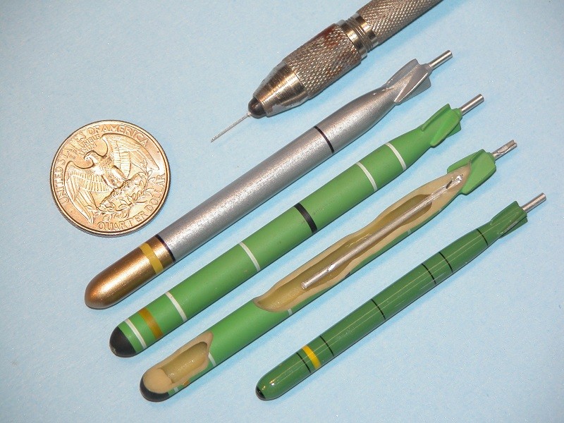
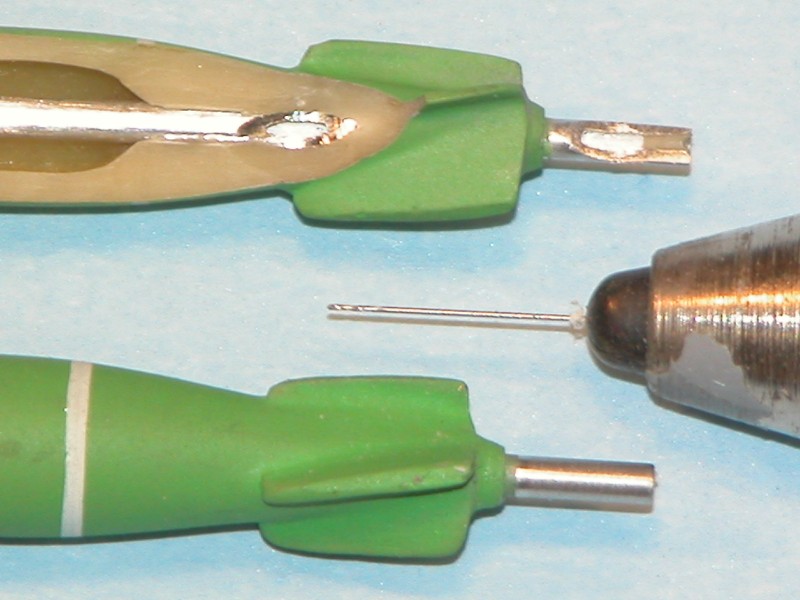
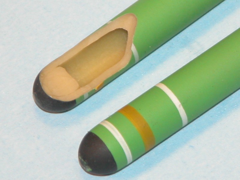
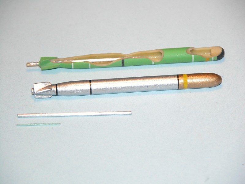
A simple analogy can be made, the resin at the ends of the aluminum tube is equivalent to two throttle valves.Originally posted by redboat219
Comment
-
-
-
Skipjack's torpedo tube arrangement is similar to that of Gato's, except that the whole thing is "sideways". So with a mechanical launch system, the Gato's torpedo launch system should roughly match the Skipjack's, albeit with some “inconsistencies” .
The use of solenoid valves for pneumatic firing certainly simplifies the complexities considerably, regardless of the number of torpedo tubes, or the shape of the arrangement, it's not a problem, I think maybe just less of the "fun" of mechanical firing. I think the limitations of the mechanical firing mechanism are relatively large. The overall structure of the submarine, the number of torpedo tubes, and the overall shape of the torpedo tube arrangement (the simplest example is the difference between modern submarines and WWII pro-submarine torpedo tubes) all have a direct impact on the complexity of the mechanical firing structure. For example, in the picture below, the Israeli Dolphin class, with 10 torpedo tubes, arranged quite neatly, is simply a beast...
V
Comment
-
I ran David's torps with butane gas, less energetic as the gas he used, they ran more controlled but lesser range, made no alterations to the nozzle.
Manfred.I went undergroundComment
-
I believe that the safety of torpedo launch systems is considered from a number of angles, not just the speed of the torpedo. The structure of the torpedo itself and the choice of gas are the two main directions for improvement. At present I propose a method of improving the torpedo itself, while the choice of the gas should be considered in a comprehensive manner. Yes, it is true that butane has less pressure than tetrafluoroethane (R134a), although R134a is a relatively low pressure among the many refrigerants. But all things considered, butane is highly flammable and a little static electricity can even turn a torpedo into a ''fire-breathing missile'', as most alkanes are flammable. I chose R134 because it is non-flammable, harmless to humans, has a relatively low pressure, and is globally recognised as an environmentally friendly refrigerant that is not harmful to the ozone layer. Of course, the exact choice will depend on Mr Merriman's own experiments.
VComment
-
Today I am rethinking one of Mr. Merriman's torpedo launchers, trying to solve the problem that puzzled me before. This launcher differs from the 1/72 Gato launcher in its pushrod construction.
In the 1/72 Gato launcher, the ratchet is held in place by a bar-shaped brass locking sleeve (similar to the 1/72 Alfa construction). When the push rod moves forward, the brass locking sleeve drives the ratchet forward. However, this launcher does not seem to have a brass locking sleeve, but simply relies on a push rod to make the ratchet rotate. I did a small experiment and found that just relying on a push rod does not seem to make the ratchet rotate, after the first push rod to push the ratchet, the second push rod and then forward movement will not contact the ratchet.
In the diagram below, I divided the push rod into part A and part B. I observed that part A seems to be thinner than part B, which means it is not the same push rod, but two parts.
So I made a hypothesis, in the diagram I drew below, are part A and part B connected by a hinge? The original photo is a bit blurry and the key parts are obscured, so I can only guess: the vertical thin copper rod soldered to the thin copper plate is used to hold part A so that it does not wobble, and the twisted thin copper rod is also used to hold part A, while giving it a force to press in the direction of the vertical thin copper rod, so that it can just touch the ratchet. Because of the hinge (which is the key), as the push rod is pushed or pulled, part A is constantly pushed up by the ratchet or pushed down by the twisted thin brass rod (which touches the ratchet before the next movement).
So, this is my guess, and I hope Mr. Merriman can evaluate if I am right or wrong if he can.
V
Comment
-
In WWII or WWI submarines, most torpedo tubes were fixed in the submarine, with external (non-reloadable at sea) torpedo tubes or internal torpedo tubes (reloadable at sea).
Reference link:Torpedo Vorhaltrechner Project - Submarine external torpedo tubes (tvre.org)
There is an alternative torpedo launcher, more complex than the previous two torpedo tubes structure, and easy to damage and failure, that is trainable torpedo tubes. An interesting fact is that two trainable torpedo tubes were originally fitted to British WWI submarines of the K class, but were later removed because they were easily damaged in the waves. trainable torpedo tubes were common in WWII French, Polish and Dutch submarines.
There are two pairs of Trainable torpedo tubes in the stern of the Surcouf submarine, six in total:
WW2 Polish submarine Orp Orzel:
V
Last edited by Sam Victory; 12-16-2021, 01:50 AM.Comment


Comment