-
Of the approximately 40,000 men who served on U-boats in WWII, it is estimated that around 28,000 to 30,000 lost their lives. -
I’m Dickens, He's Fenster.Of the approximately 40,000 men who served on U-boats in WWII, it is estimated that around 28,000 to 30,000 lost their lives.Comment
-
How’s the type XXIII coming along?Comment
-
Structurally the only assembly work left is the sail and to integrate my 'fitting kit' control surfaces and linkages to the hull. Part of that fitting kit is the foundation to which the 1.25-inch FPV enclosure resides. I'll spend tomorrow working up the next installment to this thread -- mostly dealing with how the camera-transmitter antenna is replaced by a length of coaxial cable so that the transmitters antenna can be placed high atop the periscope.


Film at Eleven. I'll show things off during Saturday's Zoom meeting.
DavidWho is John Galt?Comment
-
Can I join your meeting?Make it simple, make strong, make it work!Comment
-
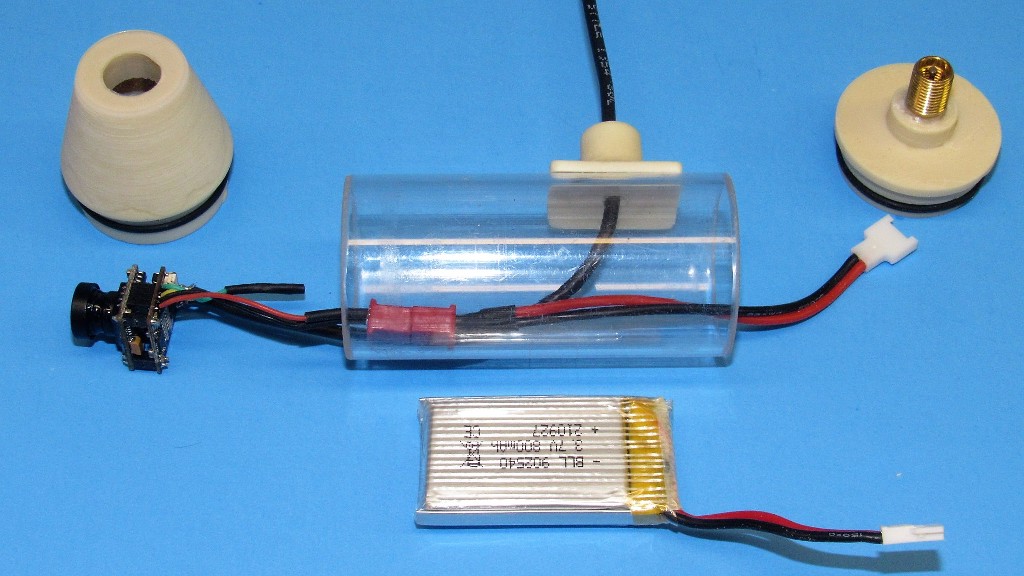
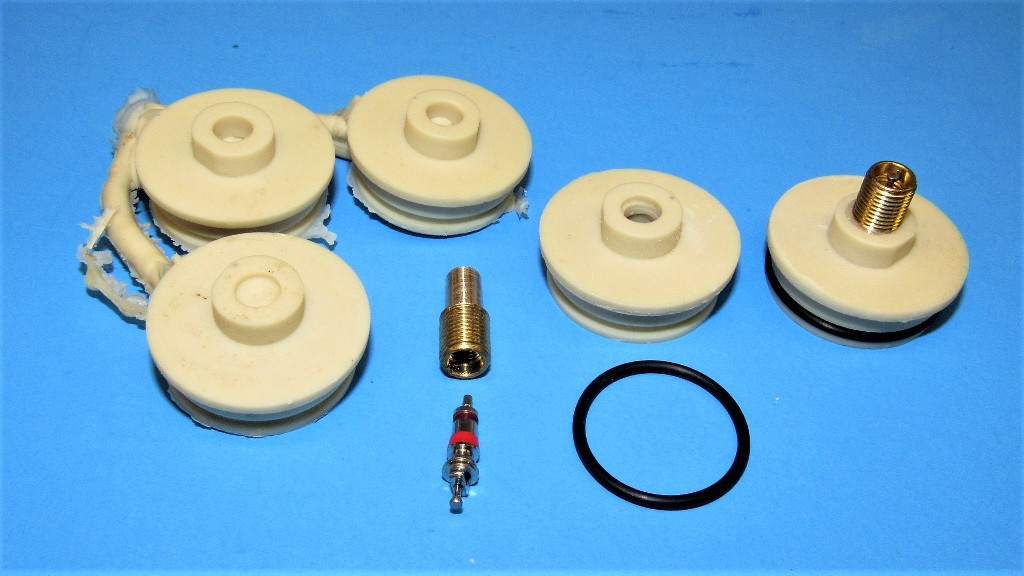
So far, I've got two fully functional watertight FPV systems up and running. I've got finished parts for another three. Here's all it takes: The antenna modified 5.8gHz camera-transmitter unit (about $17 on Amazon!), a little 1S Lithium-polymer batter, and the enclosure itself.
As the camera-transmitter was designed and and sold for use by the r/c plane and drone fliers, the orientation of the antenna is vertical, this to ensure maximum RF transmission to the vertically oriented ground-station receiver antenna. But this arrangement won't fit the watertight enclosure; additionally, there remains the need to move that antenna about a foot or more away from the unit, up through the sail, and up into one of the masts that will place the vertically oriented antenna above the waters surface.
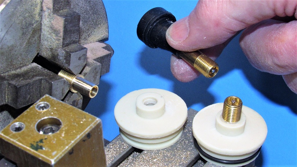
The stock camera-transmitter antenna is removed, and a horizontally oriented length of RG-178 coaxial cable soldered to the appropriate pads on the after face of the transmitters PCB. To the left a stock unit. To the right, a modified unit. A simple solder job.
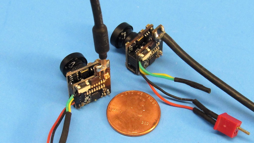
Now, with a length of coax replacing the stock antenna, that little sucker will fit!
Though this specific demonstration is to a 2.4gHz receiver antenna, it does illustrate how the factory antenna is replaced by a length of coax. The objective is to solder the coaxial cables central conductor to the PCB's 'antenna pad', and to solder the RF shield to the PCB's 'shield pad'.
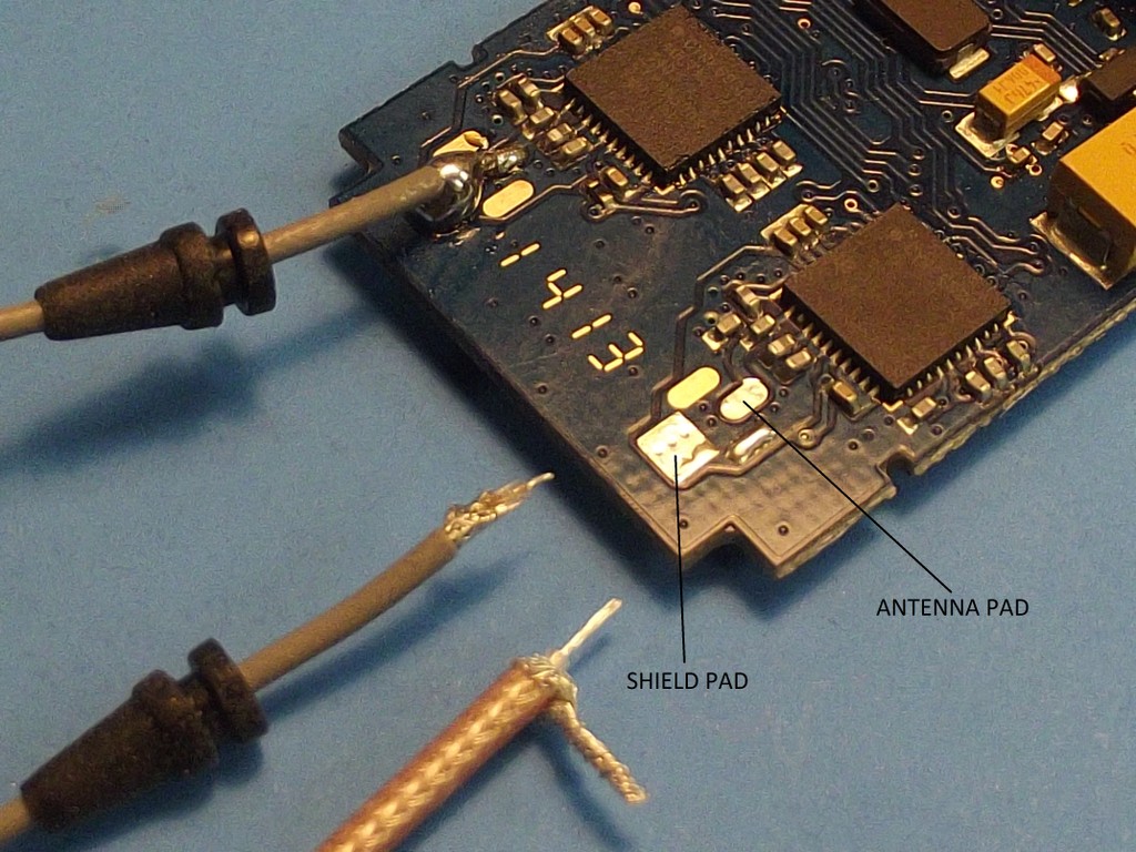
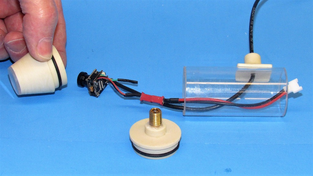
The other end of the coax becomes the systems transmitting antenna simply by removing a portion of the shield; making the central conductor (now the antenna) watertight; and hiding it with a hollow scope-head or other retractable mast situated well atop the sail. The objective is to keep the antenna in the air as the model cruises along at periscope depth.
No way the camera-transmitter standard antenna orientation would fit into the forward bulkhead of the watertight enclosure. Hence, the need to not only change the run from vertical to horizontal, but to also run the coaxial cable up to the top of a raised mast and terminate it into a vertically oriented antenna there.
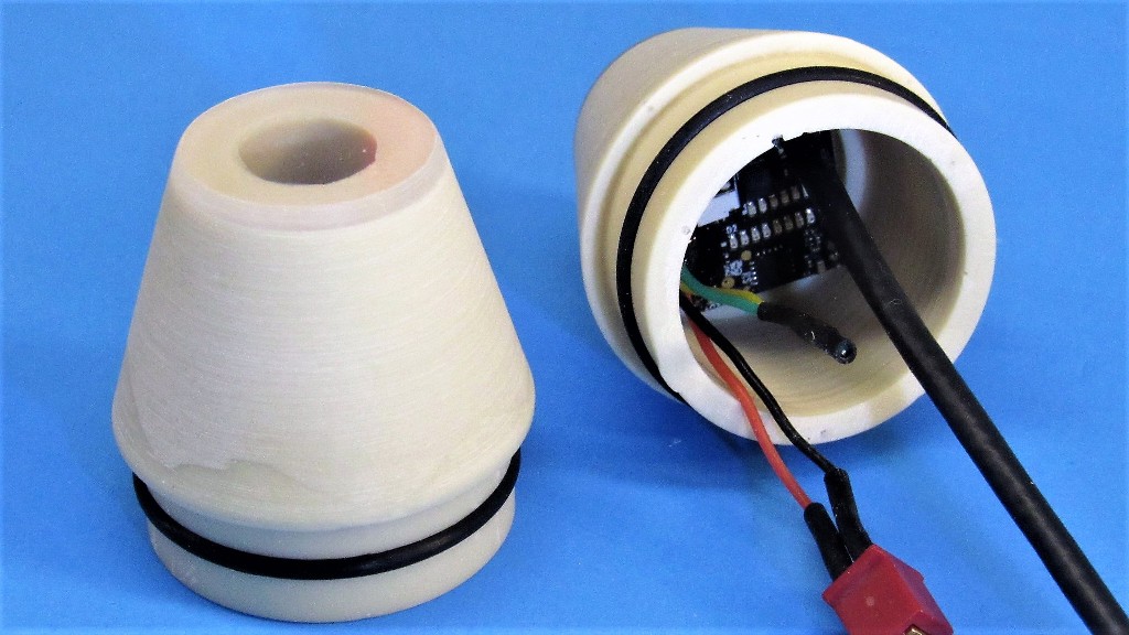
The clear window through which the camera lens peeps is a 1/16-inch-thick piece of Lexan sheet that had been cut to a rough disc, CA'ed to the forward end of the forward bulkhead, then turned on the lath to make the windows edge conformal with the bulkheads body.
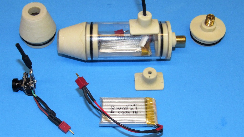
The FPV system enclosure features a removable cast resin forward bulkhead used to gain access for turning the system on and off (by simply plugging in or unplugging the battery to the camera-transmitter), or servicing such as battery swap or transmitter band-frequency re-assignment. An equalization valve within the bulkhead is used to vent off the slight over-pressure whenever the forward or after bulkhead is pushed into the enclosures cylinder. This reduces the possibility of the heated air from within (a result of transmitter waste heat) expanding to the point of blowing one of the bulkheads away from the cylinder with catastrophic consequences.
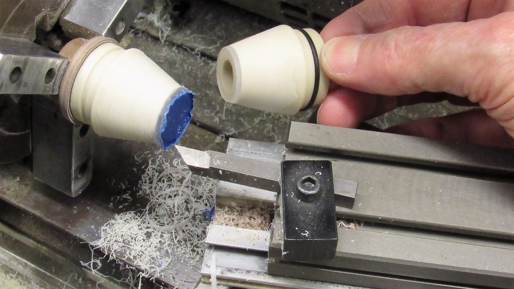
The equalization valve is simply a modification of a standard Schrader type tire-valve you can purchase at any car-supply store. The valve core is removed, most of the stem is chopped off, what remains of the units shank is turned down to the diameter of the bulkheads hole, I go for a 3/16-inch diameter fit. Gluing the modified Schrader valve into the bulkhead, re-install the core valve and I'm done.
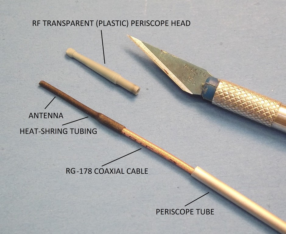
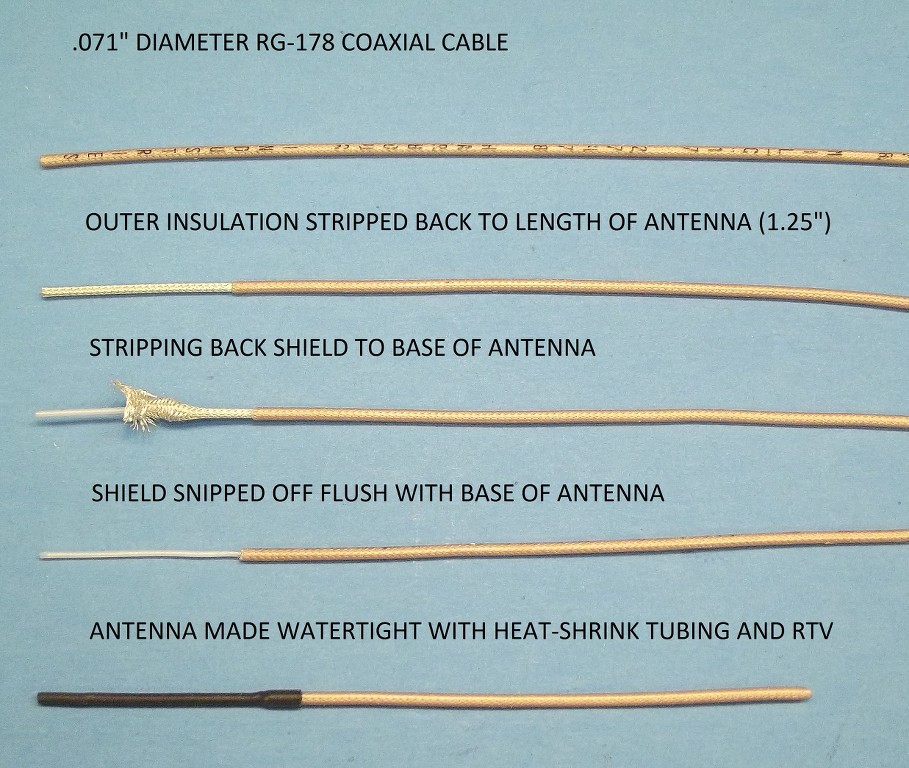
The steps needed to create the antenna element at the end of the coaxial cable is illustrated in this picture from top to bottom. The objective is to create a 5.8gHz antenna by removing a specific length of the coaxial cables shield, and then making the exposed conductor (which become the RF radiating element of the system) watertight.
Note: this photo illustrates the antenna length of a 2.4gHz system. The correct antenna length of the 5.8gHz system is exactly .508-inches.
 Who is John Galt?
Comment
-
David, is the pod bouyant enough to be used as a tow fish?Make it simple, make strong, make it work!Comment
-
How about a universal cradle mount that you can strap on to the hull of other submarine hull like the Skipjack or Type VII.Make it simple, make strong, make it work!Comment
-
Not sure what you're planning for a recorder then. A small SQ11 camera will fit I think, but the quality won't be as good as the current state of the art.
I would personally look at a small ellipsoid shaped enclosure with a axial seal to maximise depth whilst keeping the width small enough to fit within the confines of the fin, although it would compromise the strength of the enclosure a bit, doubtful it would be an issue at the depths we go to.
You could probably get away with a cylindrical shape if you dispensed with the clear tubing and made a custom thin walled epoxy glass item that matched the contours of the fins width.Comment


Comment