-
Practical wisdom is only to be learned in the school of experience.
"Samuel Smiles" -
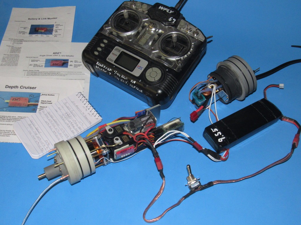
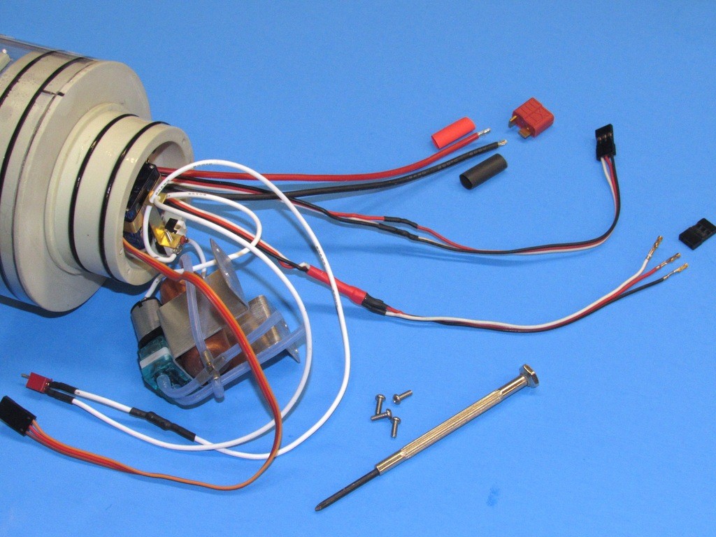
The electronic devices within the cylinder are commercial products with leads usually longer than required to reach the receiver. Aboard the Modular SubDriver the receiver is the nexus from which most propulsion, control, and ballast sub-systems receive their intelligence.
To get everything to work as a system its good practice to first arrange all the electrical and electronic devices outside of the very cramped MSD and get things operational. Problems are identified and corrected easily at this stage and some of the setup protocols performed. Some setup tasks have to be differed until the devices are installed within the MSD.
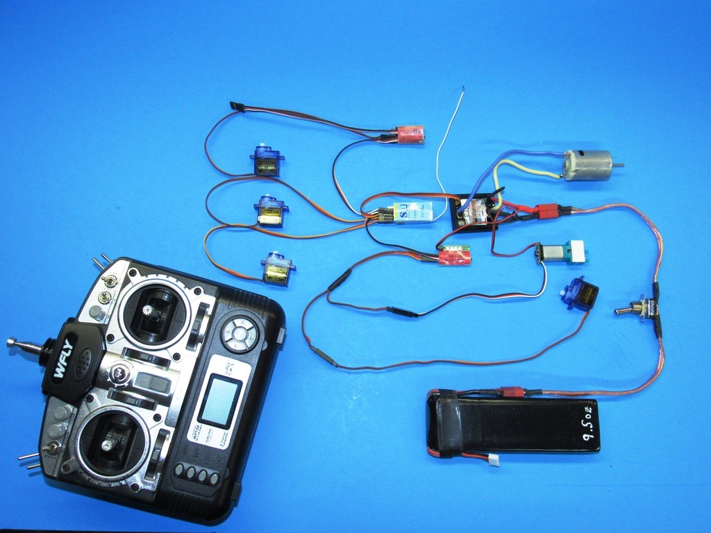
Longer than necessary leads within the tight confines of the cylinder not only makes for a messy arrangement, they also act as antennas that capture spurious RF energy and pump it into the receiver where that noise could swamp out the transmitted signal.
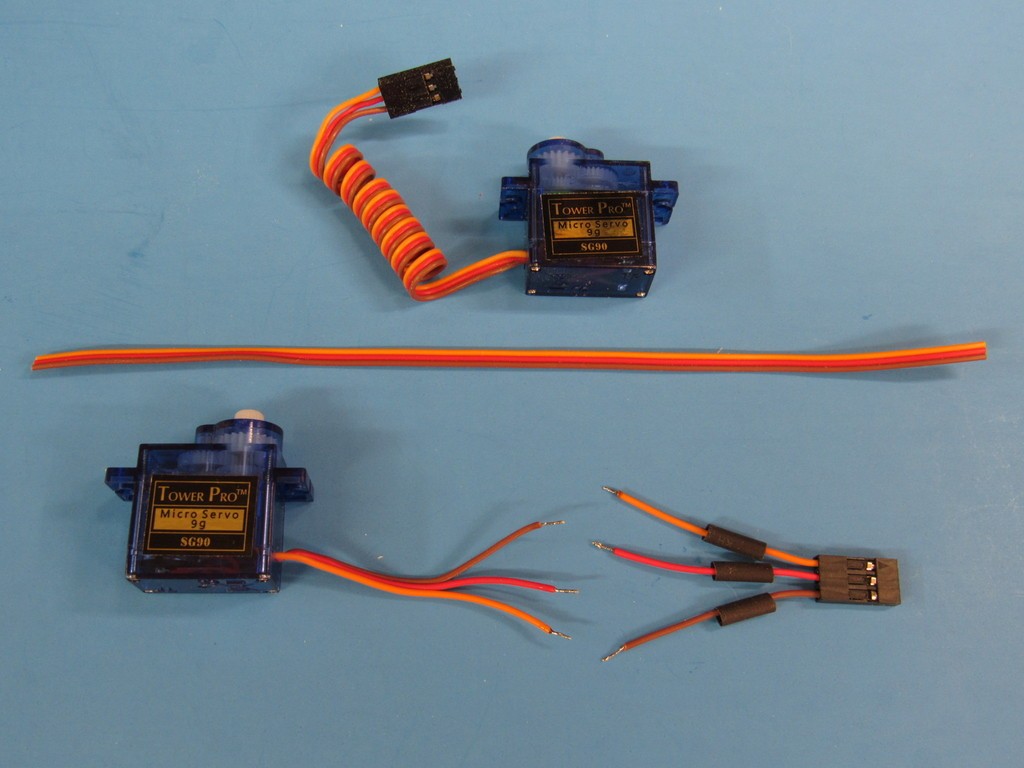
Long leads bad.
Short leads good.
Each lead is shortened but for a little slack to alleviate any strain on the wires, plug and PCB. Getting rid of all that spaghetti makes for a much tighter assembly within the cylinder and greatly reduces the possibility of RF noise causing self-glitching.
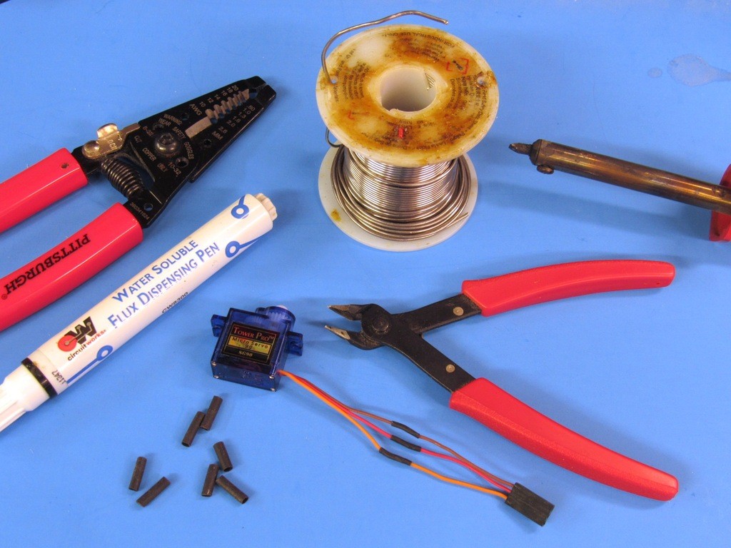
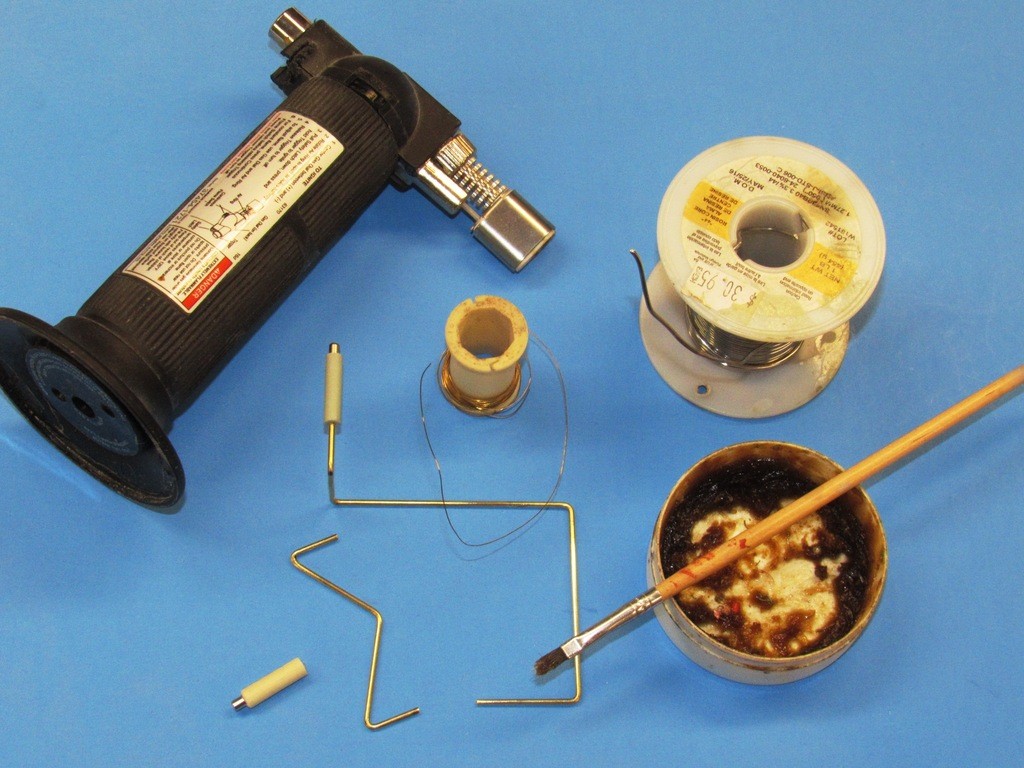
Dykes, wire-stripers, solder, 25-Watt soldering iron, non-acid flux, heat-shrink tubing, and patience, outside door secured so that screams of rage don’t disturb the neighbors, and the leads are sized to suit the devices distance from the receiver.
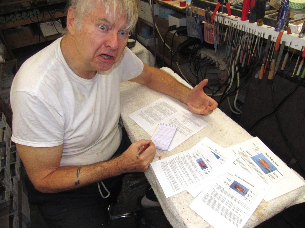
Gathering, testing, programming, and integrating the electrical and electronic devices – wrangling all the magic gizmos that make the damned thing work, are tasks I loathe doing; these aspects of r/c model submarine building and operation interest me not in the slightest!!!!
I’m competent enough when it comes to donkey-work like hooking up receiver to servo or ESC, that basic stuff I can handle, any moron can do that! BUT, what frosts my butt; what drives me nuts; what sets my hair on fire, is the task of ‘setup’ of the two devices unique to r/c submarines: the Battery Link Monitor (BLM) and Angle Driver (AD2).
I’ve read and re-read the instructions and simply cannot get a setup to work right the first time. To be fair to the product, I can think of no better word description than what Kevin has authored in the instructions.
Apparently I’m not wired to translate written instructions into the perfectly choreographed button-pushing, and transmitter stick twiddling actions needed to get the devices to talk to one another in a civil manner. I NEVER get it right the first time. But, I’m a special type of hard-head; I eventually get the damned things working right. Given a choice between chewing broken glass and setting up these devices I would have to think about it a few moments.
I hate this ****!
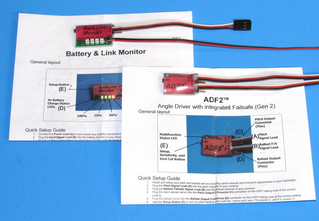
Don’t get me wrong. No one on this planet appreciates the availability and utility of these devices more than me; particularly the units produced by Kevin McLeod of KMH. His devices present small foot-prints, are rock solid, and consume very little current. But, because of the sophistication of their operation and enhanced capabilities, these devices -- specifically the Battery Link Monitor (BLM) and Angle Driver (AD2) -- demand full attention as you attempt to follow the instructions. Programming is specific to the model, r/c system, and battery type. One size does not fit all.
Only r/c submarines require a device to autonomously drive the stern planes to keep the model horizontal when running underwater; and a fail-safe device to blow ballast water if the signal is lost (not a unique requirement in itself to r/c submarines), and also actuates if the battery voltage drops to a dangerous level.
(The ADF2 pictured below is an older type that featured an integrated fail-safe circuit, but that chore is now handled by the BLM).
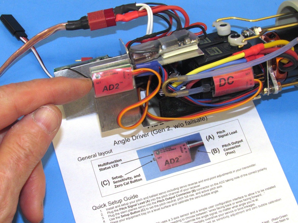
Setup of the BLM can be done before putting it into the cylinder, but if care is taken to make it assessable once mounted – you have to get at it to push the ‘set-button’ – there’s no problem programming it in situ. As you can see I’ve mounted this device on the side of the starboard (stern plane) servo.
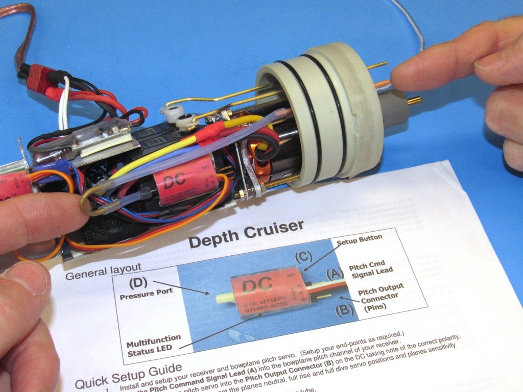
A simpler setup routine is employed to get the Depth Commander (DC) device up and running. This optional piece of gear drives the bow/fairwater planes to maintain the last commanded depth setting. It can be commanded off and on from the transmitter. Slick! This device is not vital, but something I’ve come to embrace.
You see, I’m a bit of a cow-boy when it comes to mixing it up with surface craft (targets) at the lake. The DC greatly reduces operator work-load as one weaves in and out and under the surface pukes. Much good fun to be had busting up the regimentation of a nicely arrayed battle-group.
“What? Something spooked you guys? There were collisions? You all should work on your group discipline … just say’n”.
RHIPMF’s
The AD2 has to be set once mounted on the MSD’s device foundation. This is because the devices reference plane is gravitational force and the basic setup operation tells the devise which-way-is-up.
The Battery Link Monitor is a device that, in the fail-safe modes, autonomously commands a ballast tank blow if there is a Loss Of Signal (LOS) between transmitter and receiver; and/or the battery runs down to a preset low-voltage point.
The monitor mode logs the number of LOS events occurred during the last sortie. Informing you to what degree the body of water you are operating in is attenuating the transmitted signal. Good to know stuff as you prepare for the next patrol. It’s been my experience that any body of water, be it pool or lake, has its radio ‘dead spots’ which when identified should be avoided when operating the model submarine submerged. The BLM’s monitor is a very useful feature in that it helps you survey the patrol area for these no-go locations.

Who is John Galt?Comment
-
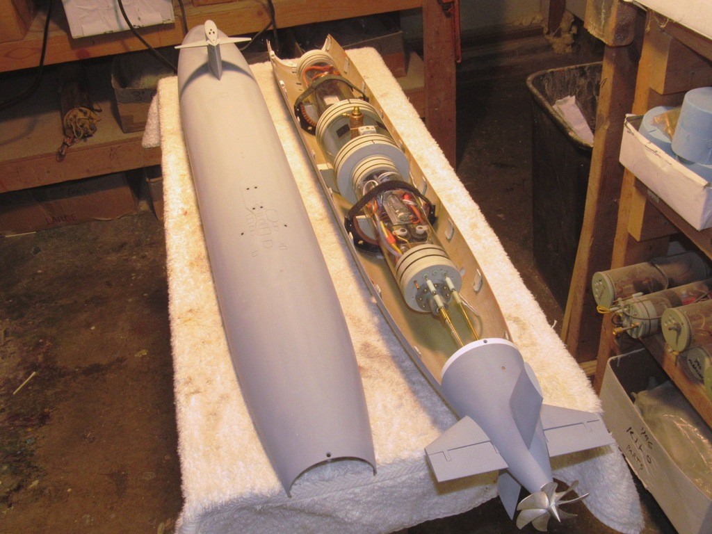
Mocking up of the Modular SubDriver is over, I’ve just finished populating the proof MSD with the devices needed to make it operational and tomorrow I set about the tasks of certifying the unit for operation (leak-check and proper operation of the SAS ballast sub-system). And, with that, the time has come to integrate the MSD with this old 1/72 THRESHER class r/c submarine hull and check this puppy out in the water.
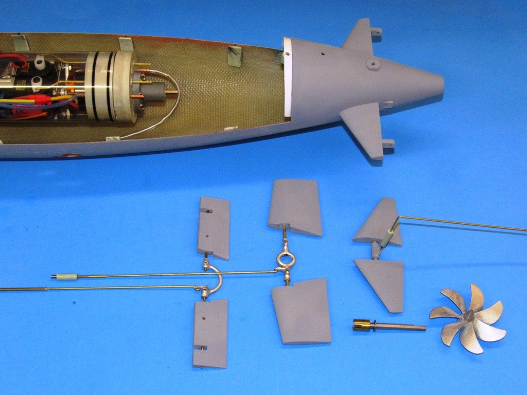
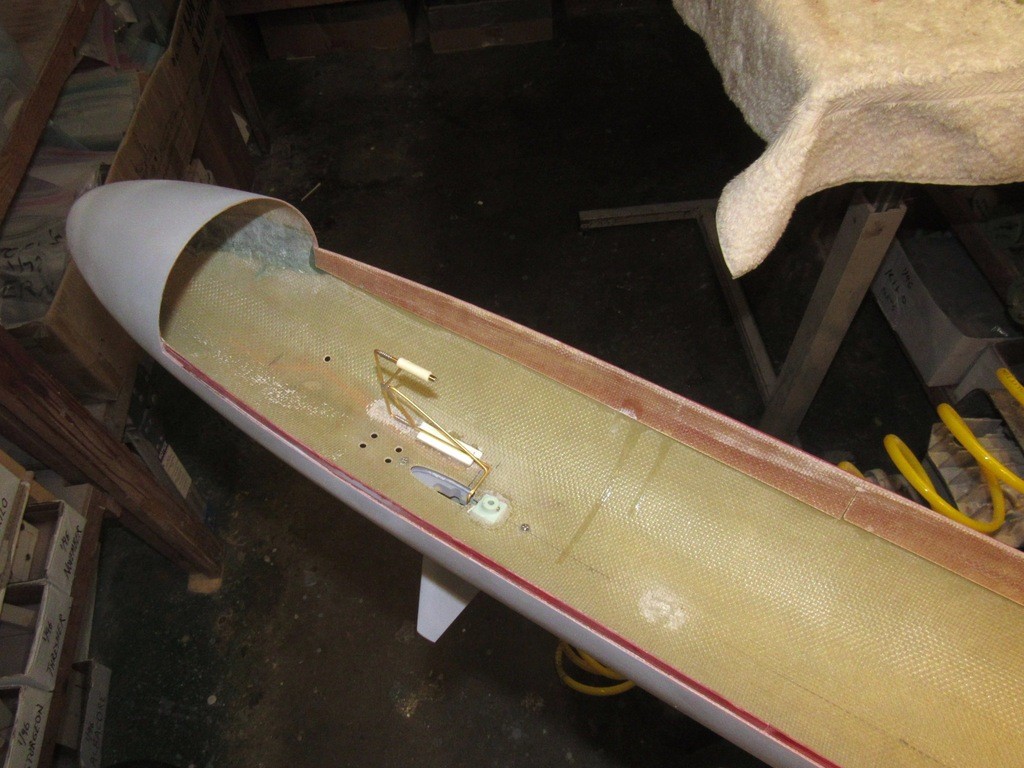
The rudder and stern plane linkage was a straightforward affair. The control surfaces connecting through a ‘yoke’ that not only served as bell-crank but also the means of providing clearance for the centrally running propeller shaft.
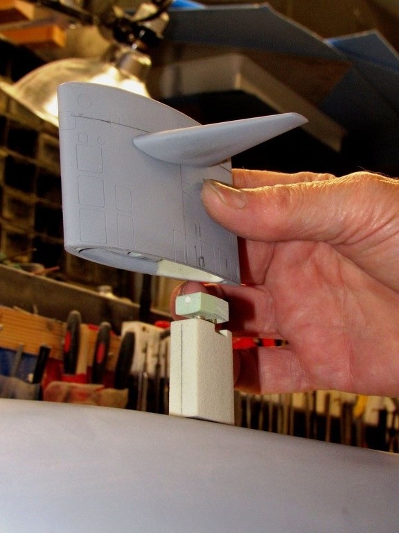
The sail planes differed in that the bell-crank was formed from two ‘floating’ magnetic couplers that translated axial motion to rotational motion; a bell-crank in function but not requiring making up fittings within the tight confines of the THRESHER’s very narrow sail.
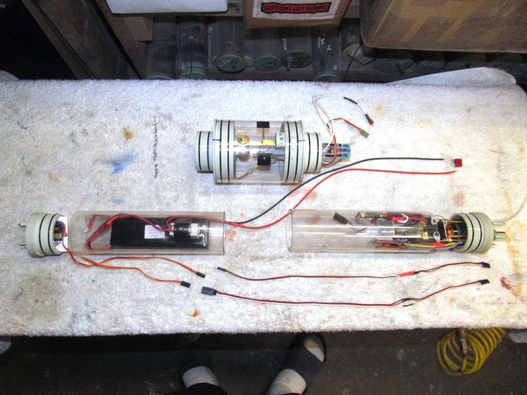
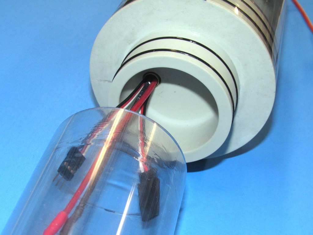
Arraying two, even three different diameter cylinder sections into a MSD presents its own special problems over a constant diameter SubDriver. At least three support saddles are required, each sized to fit the cylinder over it. And there are no mechanical fasteners holding the three cylinders together, only O-ring friction retains each cylinder in place on its accommodating radial flanges. Care has to be taken to not accidently twist or bend the assembled cylinders out of alignment with one another during handling.
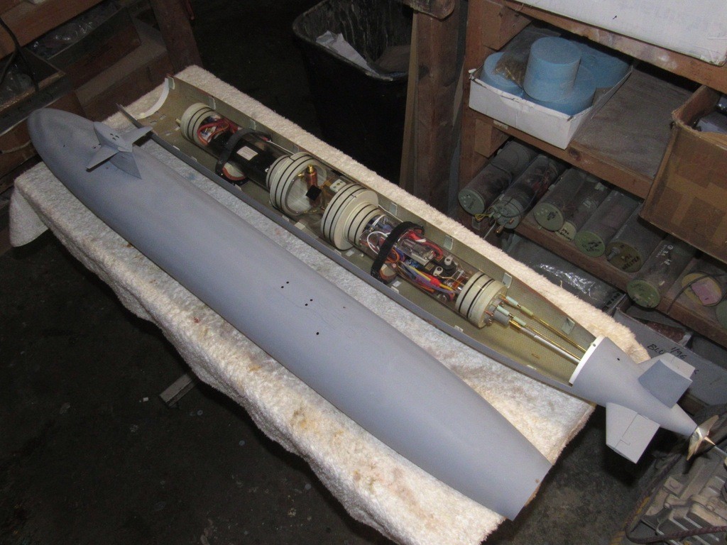
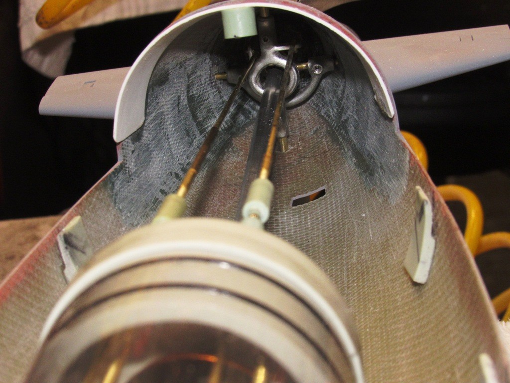
This shot well demonstrates how much annular space is made available by changing diameters of the three Lexan cylinders. As you can see, there is plenty of room for buoyant foam (to counter the weight of the fixed lead ballast low in the hull needed to produce static roll stability) between hull and MSD.
You can just make out the two pushrods extending forward from the face of the forward bulkhead. One has already been outfitted with a magnetic coupler and will actuate the sail-planes; the other pushrod will eventually operate the four torpedo launchers through an escapement sequencer – but I won’t pour time into that till I first validate the MSD. The model here is, after all, a test-mule and the primary mission is to weed out problems not yet identified.
A close look at the stern plane and rudder yokes. Note how they are shaped to permit unobstructed passage of the intermediate propeller drive shaft. These are cast from white-metal (Tin and Antimony) in a two-part, disc shaped, rubber centrifugal tool.
My first attempt to work a linkage between the servo, located within the forward bulkhead of the MSD, and the planes set up high on the sail. It just did not work out. What should have been axial motion instead, because of the magnetic couplers propensity to shift laterally, resulted in severe binding and loss of motion; the entire exercise an example of bad design from beginning to end and the lack of good sense to find an alternative solution right away. Hard-headedness can sometimes be a virtue. But, usually not.
No matter how much lipstick I smeared on this pig, it stubbornly refused to be anything other than a pig. It refused to work. A half-day’s work went straight into the ****-can. Sometimes that three-pointer effort, launched at extremely high velocity, from across the shop is damned good therapy!
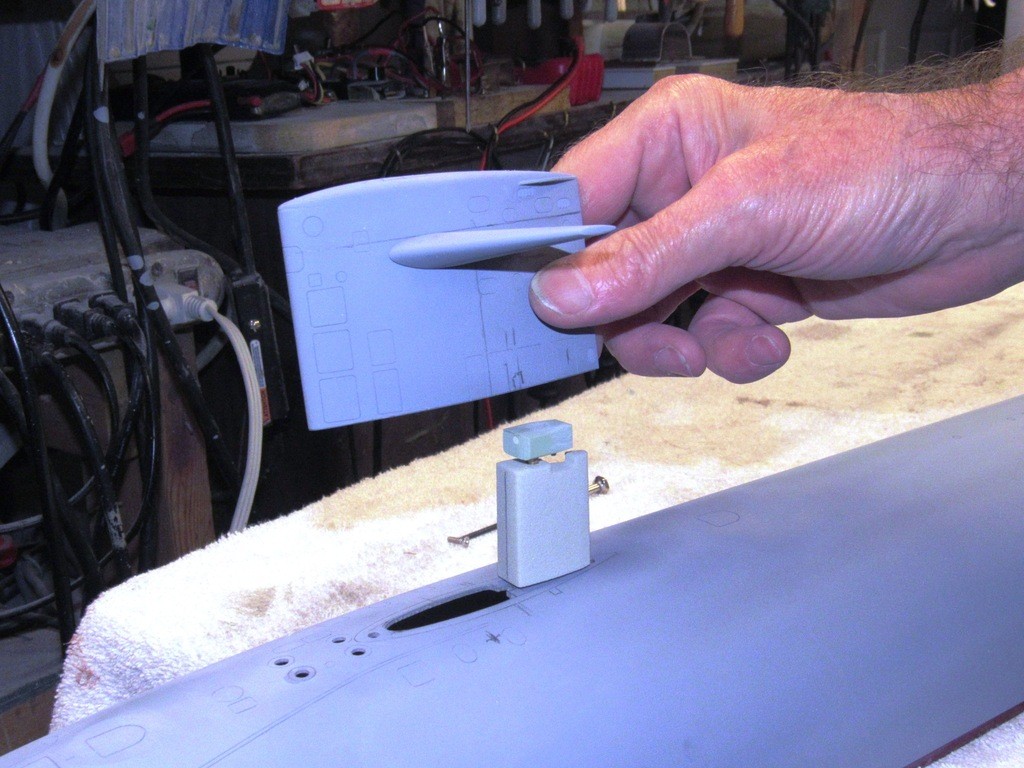
The sail is held down onto the hull with two machine screws. Not only is the SAS snorkel head-valve housed within the tight confines of the sail, so too is the linkage that operates the sail-planes. A tight fit, but it all works ... NOW!
Members of the Captain’s-conference (a body experienced submarine officers who formulated much of the desired characteristics as a new submarine design took shape) must have been away when Portsmouth designed the THRESHER class boats. That or they put a premium on ships speed and maneuverability over optical and electronic sensors.
The initial boats of the THRESHER-PERMIT class were a step-back from the electronic information gathering capabilities of the earlier SSN’s – the sail was short in beam and length in an effort to not only reduce friction, but also to mitigate the dreaded sail induces, ‘sail-roll’ of boats with larger sails that engage in high rate underwater turns at speed. The first boats featured the diminutive sail. One thing in particular must have bugged the hell out of the ship control party was the single Type-2 periscope with no radar ranging or warning antenna atop it, and minimal light-gathering ability. The distinctive small sails would be replaced on follow on boats of the class with a more comprehensive antenna and scope array housed within lengthened sails.
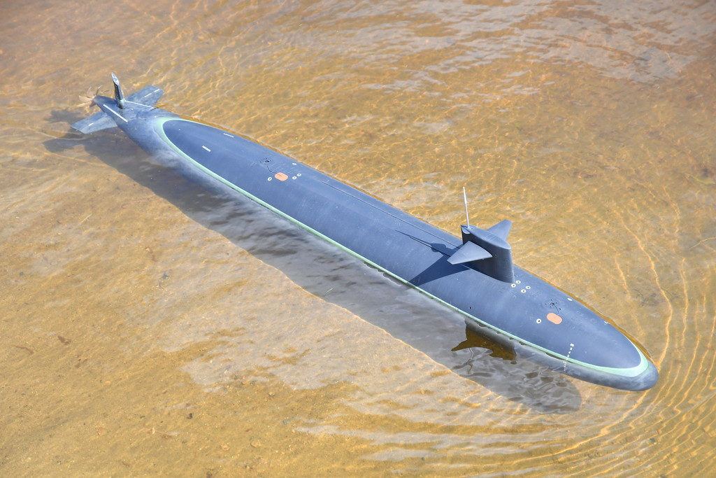
Not the current project, but one I got operational a few years back using the ‘old’ constant diameter SubDriver. Just a tease to show you the end-game.
Who is John Galt?Comment
-
Thanks and yes HE is insane.......ducking quickly to avoid the wrath.If you can cut, drill, saw, hit things and swear a lot, you're well on the way to building a working model sub.Comment
-
-
At long last, after months of consultation with my Boss, Bob Martin (who sells my stuff) I got underway with prototype work. Masters; tools; trial assembly and evaluation; re-design; master and tool modification; assembly, evaluation, and tentative approval; and finally this pre-production Modular SubDriver assembled, tested, certified, and ready to be proofed in an honest-to-god, real-life, deep-sea-wonder r/c submarine. This has taken much time, significant material, and neglect/deferral of other responsibilities. I’m confident it’s all been worth it.
At this point I’m just about done integrating the MSD with the hull; doing the 101 little things it takes to make the two comfortably compatible: working out the saddles (foundations) the MSD sits on; installing and dialing-in the control surface linkages; making the propeller intermediate drive shaft that fits between the MSD and propeller shaft; and installing fixed ballast weight in the bottom of the hull so as to establish the vehicles center of gravity at the longitudinal center of the ballast tank (itself located half-way along the length of the submarine) and low to the hulls longitudinal centerline so as to produce static stability about the roll axis. CB high, CG low; the greater that moment the more statically stable becomes the submarine.
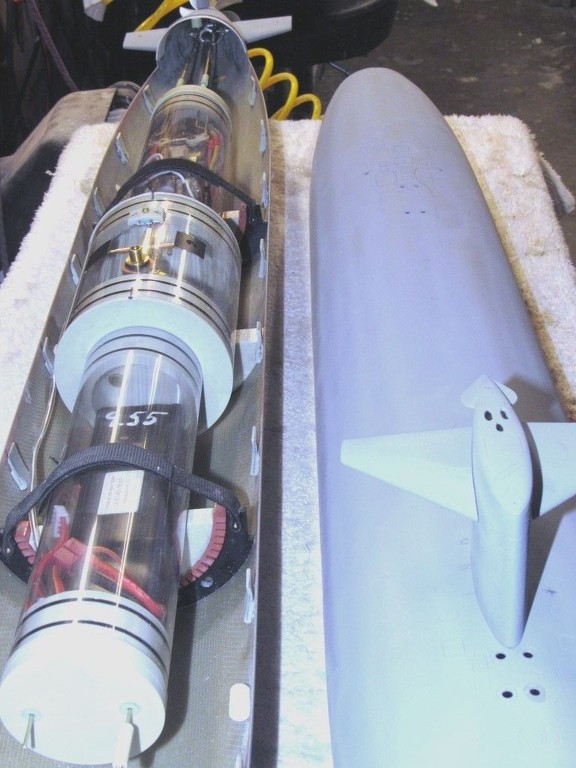
Unlike the earlier SubDriver (SD), which employed a single constant diameter length of Lexan cylinder, the modular SubDriver (MSD) presents the opportunity to integrate different lengths and diameters of cylinder in order to get a more conformal fit of system to hull. The separable cylinders afford quicker and easier access to the devices within the system.
Driving home Darren Scannell’s recent cautionary posting to the Warships Models Underway forum, is the problem I encountered after splicing servo lead wires together – I wound up with thickened leads which were very hard to pass through the narrow confines of the ballast tank conduit (a 5/16” brass tube) interconnecting the forward and after dry spaces.
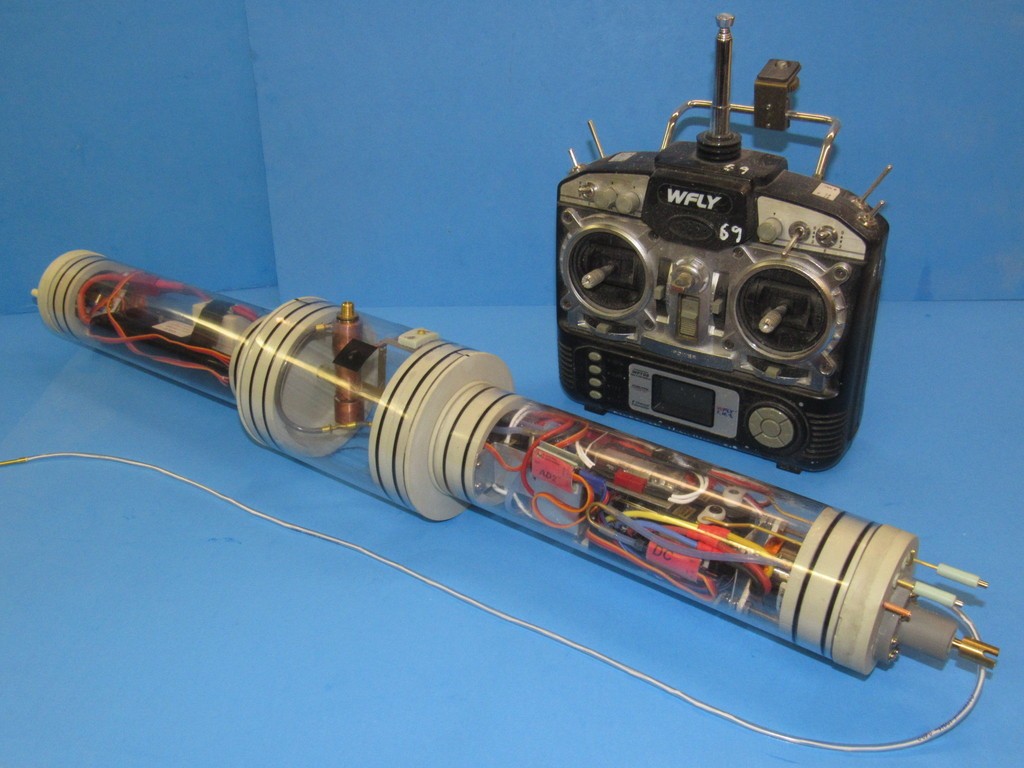
The magnetic mission-switch greatly simplifies system start-up and shut-down. With this very useful device there is no need for a boot-seal over a mechanical switch toggle, or need to pop the forward bulkhead on and off its cylinder to access an internal switch.
Though making for a difficult cable-run through the conduit, there is much to recommend placing servos at the extreme front end of the MSD. No need for long external pushrods running from the SD’s motor-bulkhead to the front of the boat; less clutter, in the form of pushrods in the annular space between SD and hull; and by reducing elements of the linkages you eliminate stiffness, non-linear response, and back-lash.
(This feature of the MSD – the placement of the two servos up front almost did not happen, and resulted only at the insistence of Bob Martin. He’s built up and got more r/c submarines in the water than anyone I know, so when he makes a ‘suggestion’ like this, I snap too and get to work making it a practical, user-friendly ‘thing’. I did, and was pleasantly surprised to find the space it saved in the after dry space as well as the simplification of linkages needed to animate things near the bow of the model submarine of great benefit. We’re never too old to learn new tricks … never equate age with wisdom!)
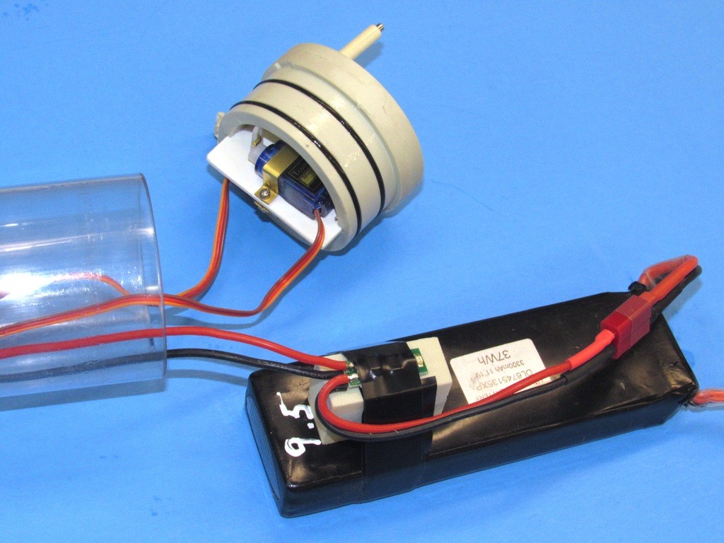
As it is magnetic influence that turns the mission-switch on and off I took care to place the device up high against the inside of the forward cylinder – this done by mounting it on a block atop the battery and securing everything together with a few wraps of Electrician’s tape. Now, without the need to flip a switch or access the forward bulkhead, I can simply turn the system on and off by waving a magnet over the MSD.
A neat feature to the magnetic mission-switch is it’s built in fuse: Should the current draw rise above 10 Amperes (there is a 25A version of the switch) it will open the circuit, shutting everything down. After a brief ‘off’ period it closes, restoring power to get the boat back.
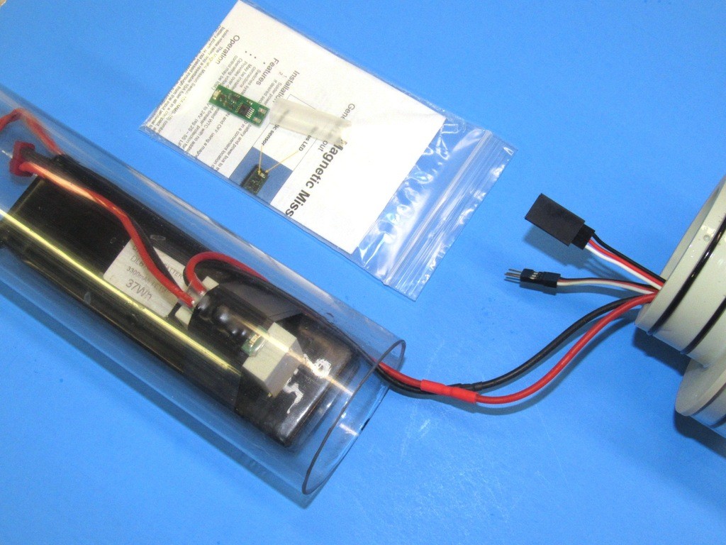
It took considerable time, care, and … always in short supply … patience to reeve all the wires through the conduit. This is the forward section of 2.5” diameter Lexan cylinder that houses the battery, two servos (fair-water planes, and torpedo launch) and magnetically actuated mission-switch. The output wires from the mission switch, and the two servo leads run through the ballast tanks conduit. A tight fit!
Who is John Galt?Comment
-
That is some incredible work from drawing to completion!
What do you think of mounting the mission switch to the inside of the forward ballast endcap?
It might shorten loops of battery connection wires and keep the switch from banging around
with the battery. Maybe like your servo tray on the forward endcap.
Attached FilesComment
-
-
What recommends your idea is that it permits battery replacement without involving the switch itself. And, as you say, shortens the output wires. And the magnetic sensor (I assume its of the HAL type) will respond to even a small magnet at a stand-off as great as one-inch, so mounting the switch as you recommend is viable from that stand-point as well.
I'll do this with the next MSD I assemble. Good stuff, Scott.
DavidWho is John Galt?Comment
-
David,
i allways follow this route for getting my servo/ adf in the front compartment of my SD, practically you don't have to use the plus and minus wire each time, you only do this once, kind of powerbus for your servo's, what you do need to do is, bringing the puls wire forward for each device connected to your receiver.
example, you brought two servo's to the front, used two complete leads, containing 6 wires, this eats room inside the conduit, doing it my way, two wires for the powerbus and two wires for the puls wire, giving you 4 wires eating less room.
With the ko hyoteki i also have the afd in front, only had to add two more wires, now i use a total of 6 wires for running all the stuff in front.
Manfred.I went undergroundComment


Comment