upgrading the SSY 1/96 ALFA kit

Collapse
X
 
  • Time
  • Show
Clear All
new posts
  • He Who Shall Not Be Named
    Moderator
    • Aug 2008
    • 12253

    #61
    Originally posted by trout
    David,
    I am chuckling because you "made" me do some research. I am acutely aware of Alzheimer's desease and sometimes fear it is happening to me (family history). So that being said, I turned to the web to just fact check myself and make sure I am not remembering wrong.
    It turns out we are both correct or for that matter neither is wrong. I got smarter, for sure. Thank you!
    peace,
    Tom
    I in turn -- holding your experience and demonstrated prows in this Craft in such regard -- was forced to check my stance on the issue of brass annealing. I too enhanced my understanding of metallurgy through my own investigation into the process. Seems the ratio of copper to zinc is what drives the alloys response to quick or slow quenching; the higher copper bearing metal softens when cooled slowly, and the low (more common) copper content brass is best quickly quenched.

    Unless specified, when you buy K&S Brass products you get the high-copper 'cartridge brass'. If you want the usual standard brass you have to ask for it, same true for 'machine brass' an other variants of the alloy.

    Good stuff, Tom

    David
    Who is John Galt?

    Comment

    • He Who Shall Not Be Named
      Moderator
      • Aug 2008
      • 12253

      #62
      After a few weeks of on-again-off-again ALFA work I’ve finally reached the point where the principle masters – the stabilizers, control surfaces, propeller, SubDriver foundations, Velcro strap foundation, indexing lips, forward propeller shaft bearing foundation, propeller dunce-cap, and secondary loop intake scoops – are completed. Now comes the job of using these masters to give form to the rubber tooling needed to produce cast resin parts, and white-metal propeller.

      I still need to finish the masters for a spin-casting tool that will be used to produce the white-metal detail parts, more on that work soon.

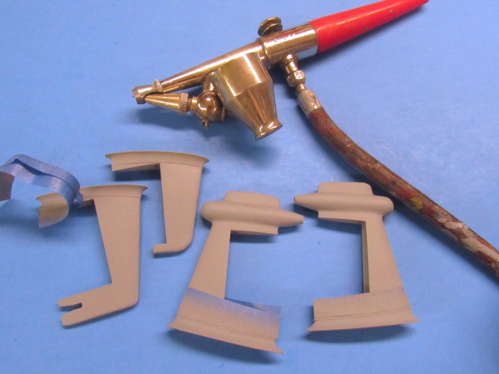
      Below I’m pulling masking tape from the top edges of the fillets at the base of each stabilizer – that tape in place during the final coat of primer to produce the desired raised edge. Tape and primer can also be used this way to represent just about any raised or inlayed item on a models surface you require. Such as plating; armor; weld-lines; oil-can dishing; access plates; diamond-deck; planking; and chipped paint, just to name a few high-relief detail items possible with the technique.


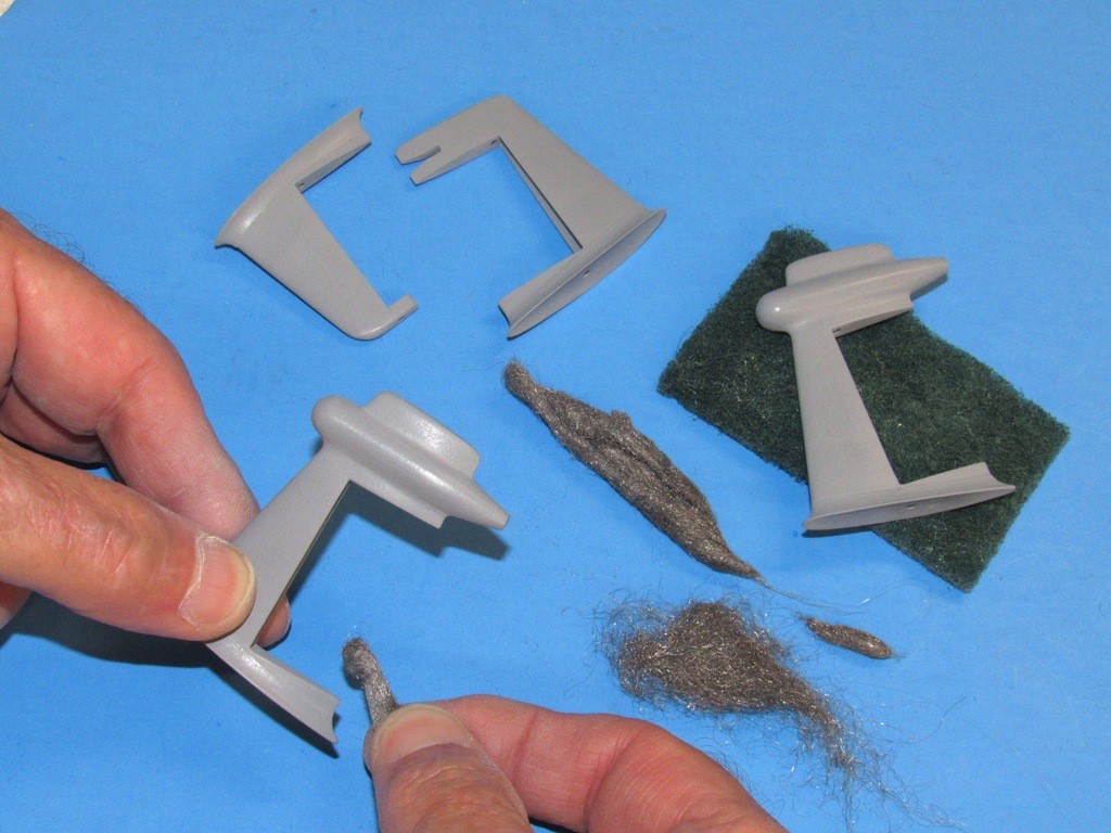
      It’s been my experience that #0000 steel wool is the ideal abrasive to give a final cutting to simple and complex curves, such as the fillets of the horizontal and vertical stabilizers seen here. On occasion a 3M abrasive pad can be pressed into service for the same type job. However, I prefer the steel-wool because of its ability to be compacted into just about any shape and size needed for the job at hand, such as the deep troughs within the stabilizers, stabilizer to hull fillets, leading edges of the planes, and tight radius transitions between outboard motor fairings and horizontal stabilizers.
      ​​


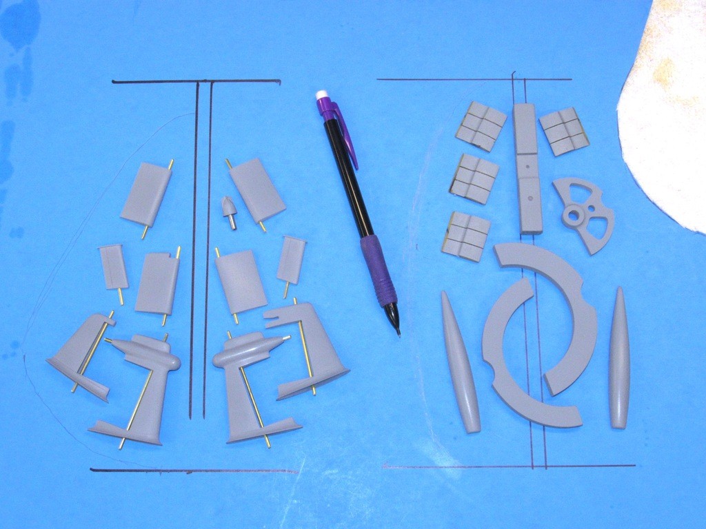
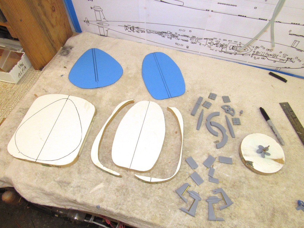
      Two tools are needed to produce the cast resin parts. Here I’m working out the best lay-out of masters over some decorative cardboard. The objective here is to minimize the amount of rubber employed to make the tool, yet insuring a lay-out that will assure proper venting of displaced air as catalyzed resin fills the tools cavities during the pour. Careful design here is EVERYTHING if consistently flaw-free castings are to be achieved during production.

      Why two tools and not simply one larger tool? The size and width of each tool and its accompanying strong-backs is limited to interior height and diameter of the pressure pots I use for resin casting.

      The masters to the left are the stabilizers and control surfaces, and this tool will feature a dedicated, centrally running sprue channel. The masters to the right, specifically the center ones, will produce cavities (the Velcro foundation and two SubDriver foundations) that not only give shape to the eventual resin, but will also do double-duty as sprue channels, off of which the outboard cavities will connect through runners to also receive the casting resin. Proper tool design is an acquired art.

      The masters are arranged atop the cardboard until an acceptable geometry is achieved and the outline of the eventual tool boarder is determined. At that point one side of the cardboard is penciled a line denoting that boarder. Since each side of the eventual tool is symmetrical to the other I simply have to fold the cardboard over and make one cut to achieve a stencil for mark-out of the mold-board/strong-back.

      ​​


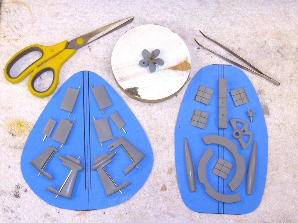
      The two pieces of cardboard were cut free from the sheet, folded in half at their sprue lines (centers), and scissors used to cut perfectly symmetrical templates.

      The propeller master was mounted on a vertically oriented 1/8” diameter shaft set into the center of a disc shaped piece of particle-board.
      ​​


      The cardboard templates are used to mark out a length of ¾” thick particle board shelf (which conveniently has a veneer of white plastic on each side). Each mold-board/strong-back cut to shape on the band-saw. These eventual strong-backs initially form the foundation for formation of the tools first half. Later, a second set of strong-backs will be cut to shape which will join the first set to sandwich the completed rubber tools, with the aid of rubber bands, during the resin casting operation. ​​


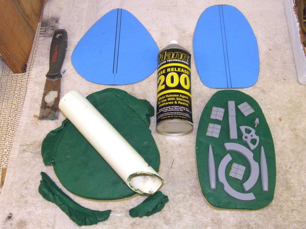
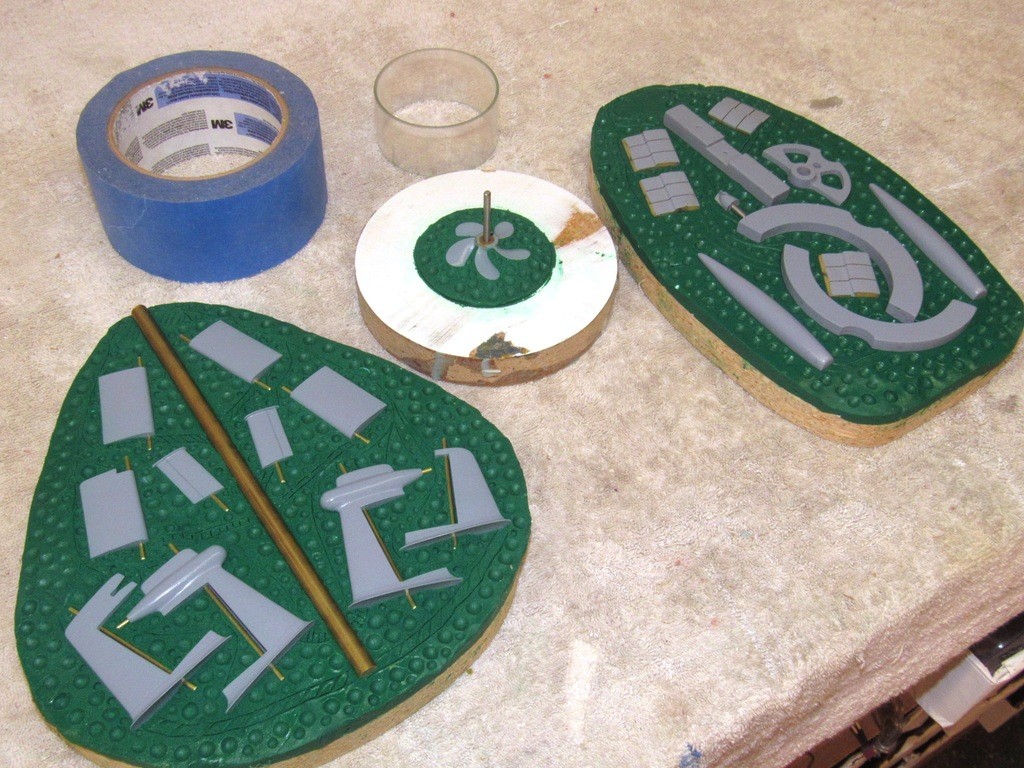
      A two-part rubber tool starts by sinking the masters about half-way into some non-sulfur clay. The clay is heated under some bulbs till its nice and gooey, then rolled out on a mold-board/strong-back till it’s about 1/2” thick and flat.


      After all masters had been pushed approximately half-way into the masking clay wooden tools (the wood is softer than the primer of the masters, preventing damage to the finish) were used to pack the clay up tight against the sides of the masters. Final setting of the masters in clay was done with a stippling brush applied with plenty of water to keep the oil-based clay from sticking to the brush bristles.

      After the vent and runners were denoted with shallow engraved lines, the flange face of each clay mask was dimpled with brush handle ends – these dimples would eventually form negative and positive impressions on the eventual rubber tool halves, indexing them together in perfect registration. A light spray coat of mold/part release insured that the clay would not be lifted by the brush handle as I pressed the tool into the work.


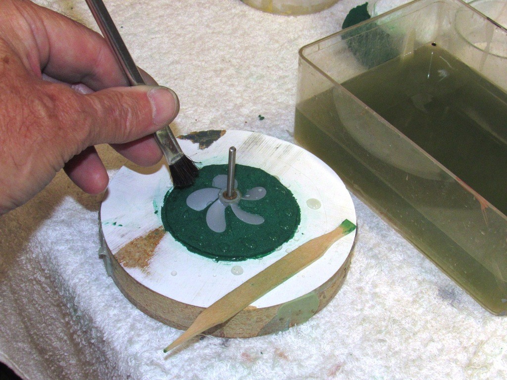
      With the propeller master sitting on its peg atop the disc shaped foundation, clay was worked under each blade, to completely mask the underside so no rubber could get at the bottom half of the propeller master. Final pushing-in of the soft clay was done with a wet, stippling brush.

      Note the wooden tool (formed from a Popsicle stick) used to do the initial clay packing under the blades.
      ​​

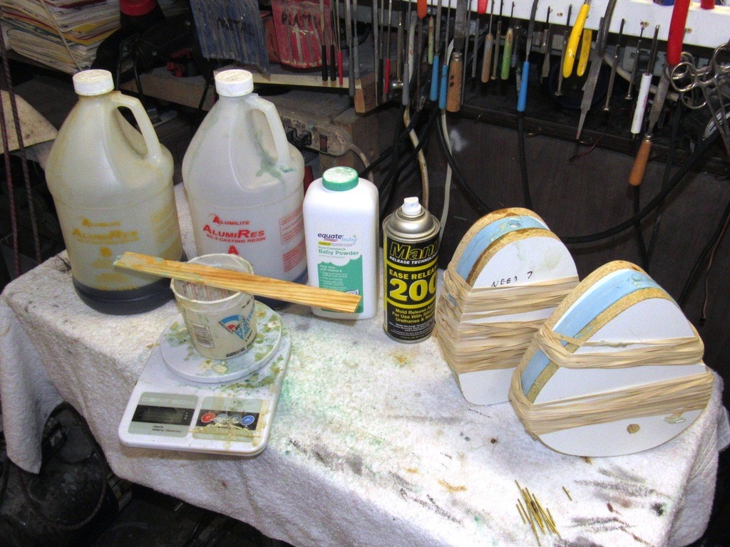
      Containment of the rubber for the propeller was simply a short length of Lexan cylinder. For the two large mold-boards I used non-sulfur bearing masking tape -- wrapped around the circumference of each mold-board -- to contain the RTV silicon tool-making rubber as it changed state from liquid to semi-solid.​​


      Last edited by He Who Shall Not Be Named; 08-20-2019, 09:12 AM.
      Who is John Galt?

      Comment

      • STARK
        Lieutenant, Junior Grade
        • Nov 2009
        • 243

        #63
        Tool Master, nice!
        What one Man can do, YOU can do too!

        Comment

        • He Who Shall Not Be Named
          Moderator
          • Aug 2008
          • 12253

          #64
          Originally posted by STARK
          Tool Master, nice!
          Coming from you, Brian, that means something!

          David
          Who is John Galt?

          Comment

          • DMTNT
            Commander
            • Jun 2018
            • 297

            #65
            Very informative. Casting is one area I still need to get my feet wet on, but haven't because I've just been too chicken**** to get started. The archives of this site need to go into the library of congress...
            Dead men tell no tales...

            Comment

            • He Who Shall Not Be Named
              Moderator
              • Aug 2008
              • 12253

              #66
              Originally posted by DMTNT
              Very informative. Casting is one area I still need to get my feet wet on, but haven't because I've just been too chicken**** to get started. The archives of this site need to go into the library of congress...
              I wouldn't trust Congress with a bag of old bubble-gum cards!

              David
              Who is John Galt?

              Comment

              • george
                Captain
                • Dec 2010
                • 727

                #67
                How near are you to production of upgrade kits?

                Comment

                • DMTNT
                  Commander
                  • Jun 2018
                  • 297

                  #68
                  That, is an insult to bubble gum cards, sir.

                  #MakeBazookaJoeGreatAgain
                  Dead men tell no tales...

                  Comment

                  • He Who Shall Not Be Named
                    Moderator
                    • Aug 2008
                    • 12253

                    #69
                    Originally posted by george
                    How near are you to production of upgrade kits?
                    Just about there, George. I still have to produce a spin-casting tool -- have to complete the mast hatch, scope heads, antennas, and bollard masters before that can happen -- which should take the rest of the week. But I'm already producing the resin parts as well as the metal propeller. Almost there. Should post the latest WIP installment tonight.

                    David
                    Who is John Galt?

                    Comment

                    • george
                      Captain
                      • Dec 2010
                      • 727

                      #70
                      Thank You for taking the time to update me/us. Sorry for being a nag on the subject

                      Comment

                      • He Who Shall Not Be Named
                        Moderator
                        • Aug 2008
                        • 12253

                        #71


                        Time finally came to complete the rubber tooling used to make the resin production pieces.

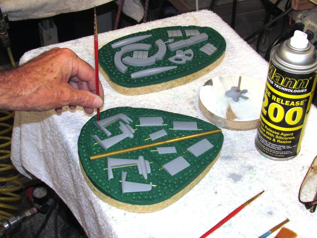
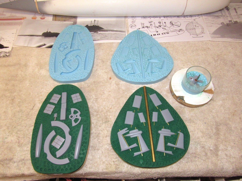
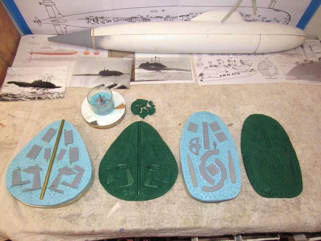
                        After the RTV silicon rubber of the first half of the two tools had cured hard, it was pulled off the masking clay and imbedded masters. You can see to advantage here how the surface of the masking clay produces the flange face of the tool half. The array of positive dimples in the rubber tool halves will produce matching depressions when the second half of the tools is poured. Note that the propeller has already been removed from its masking clay, cleaned up, and installed in the first half of its tool.


                        All master pulled from the masking clay, cleaned up, and mounted within their respective tools. The tool half to the left makes use of a brass rod to form the centrally running sprue, The tool half on the right makes use of the high cross-sectioned Velcro foundation and SubDriver foundations as sprue place holders.

                        Masking tape will be wrapped around the two tool halves forming the flask that contains the liquid rubber till it changes state to a solid. The propeller flask is simply a short length of Lexan cylinder.

                        To prevent the flange faces of the halves from permanently sticking together, the flange face of the first tool half is given a generous coating of Mann 200 part-mold release.


                        Pouring catalyzed RTV rubber to form the second half of the two big resin casting tools.

                        If the resin casting process involves subjecting the resin to one or two atmospheres of pressure during the cure then it’s vital to eliminate bubbles from the mixed rubber during the tool making process. If bubbles remain in the rubber as a consequence of entrapped air from mixing then those bubbles, in the completed tool, will collapse under pressure, resulting in positive dimples on the surface of the cast resin pieces. Can’t have that!
                        So, the RTV mix has to be de-aired before it hardens. I do this by subjecting the rubber mix to a hard vacuum. However, an alternative is to pressurize the mix after it’s been poured over the masters – hard to do! I prefer the vacuum de-airing scheme.

                        The vacuum works to enlarge entrapped bubbles in the still liquid rubber to a size where they become super-buoyant, rise to the surface of the mix, pop, and the released gas extracted by the vacuum pump. The work then continues at normal atmospheric pressure.

                        The pressure scheme, on the other hand, crushes entrapped bubbles back into solution. The pressure method of bubble elimination requires the poured rubber to be maintained in a pressurized environment for the duration of the state change – OK if you have NASA sized facilities, unrealistic if you’re working out of a converted single-car garage.


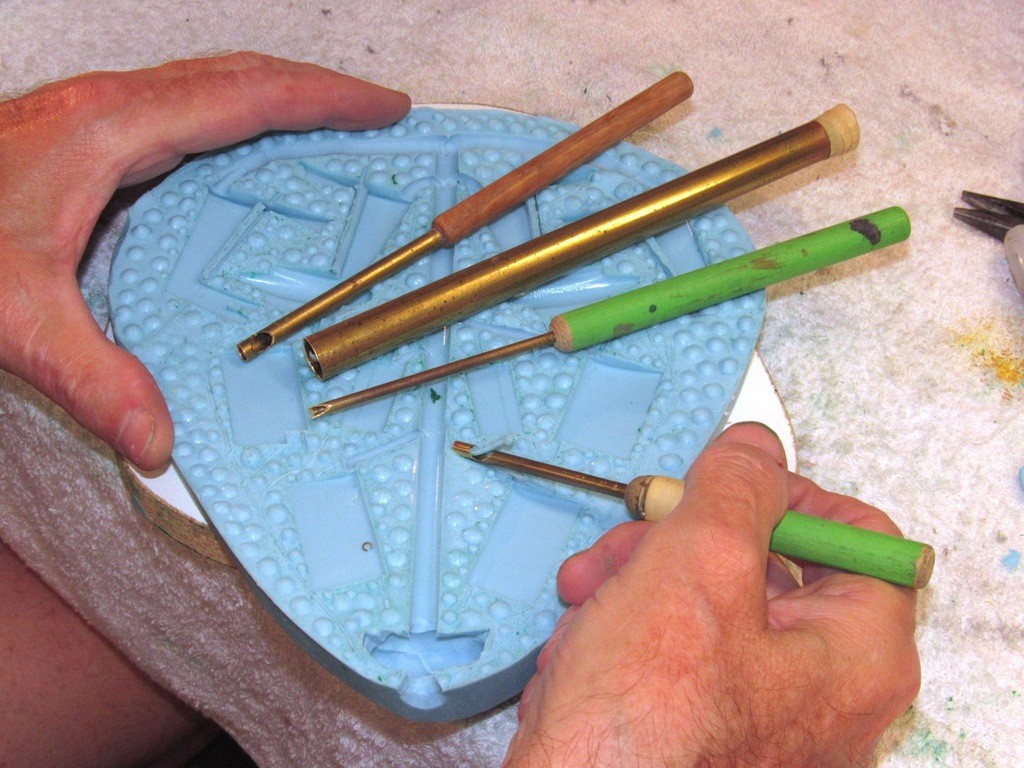
                        Onto the surface of the masking clay I had lightly scribed in lines denoting were the runners (that lead from the main sprue channel to the individual tool cavities) and vent channels would be cut into the face of the flange faces. Here I’m doing just that with a collection of different sized circular gouges and knife.

                        Note that at the top of the sprue (in foreground) has been dug out to form a reservoir – this cavity will contain make-up resin to maintain the head of resin in the sprue once the pressure pot is buttoned up and I can’t get to the tool with make-up resin. Under pressure any entrapped air remaining in the tool cavities after the initial pour will be crushed into solution and the extra resin in the reservoir will fall into the sprue making up for what the formerly entrapped air displaced.

                        Either side of the sprue hole are vents that connect to vent channeling that extends over the tools flange, each branch of which vents the high point of each cavity.


                        My favorite polyurethane casting resin is Alumilite RC-3. This quick-cure, economical, easy to work material is mixed 50-50 by weight and cures to a tan color. Check it out: https://www.alumilite.com/store/p/66...-RC-3-Tan.aspx

                        With all the runners and vent channels cut into the flanges each half of the tool was given a coating of Mann 200 mold-part release spray followed by a good powdering of either corn starch or talc powder. The powder is distributed evenly onto the surfaces of the cavities by temporarily holding the two halves of the tool together and vigorously slamming it on the table, then opening the tool up and dumping the excess powder on the floor. This results in a fine, evenly distributed film of material adhered to the silicon part-mold release. The powder acts as a wick to pull the casting resin into the tightest of cavities within the tool, insuring a complete casting no matter the geometry or size of the cavity that gives form to the eventual cast resin part.

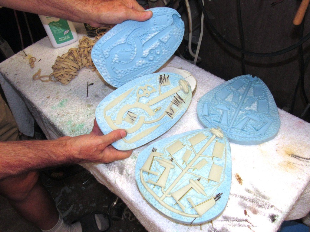
                        Shards of carbon fiber were laid into the stabilizer and capture lip cavities. The eventual stabilizer parts need strength as their high aspect ratio make them susceptible to breakage in collisions (yes, I’m an ‘aggressive’ driver … sue me!), hence the reinforcement. The capture lips need the stiffening as they are under considerable shear force when doing their jobs of holding the two hull halves in alignment.

                        I did two test shots with these two resin casting tools using rubber-bands to tightly sandwich the two-part tools between their strong-backs. These test shots revealed that, no matter how many rubber- bands were employed, they did not prevent excessive leakage of resin over the flange faces; there was not enough clamping force to minimize the formation of significant flash.


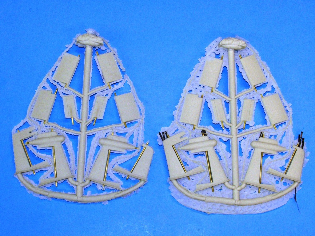
                        Here I’ve opened up the tools after removing them from the pressure pot. Note the carbon fiber shards imbedded within the capture lip and stabilizer parts. You see to advantage here the sprue, runner, and vent channel networks needed to introduce the liquid resin and vent the displaced air from the cavities that give form to the resin as it changes state from a liquid to a solid.


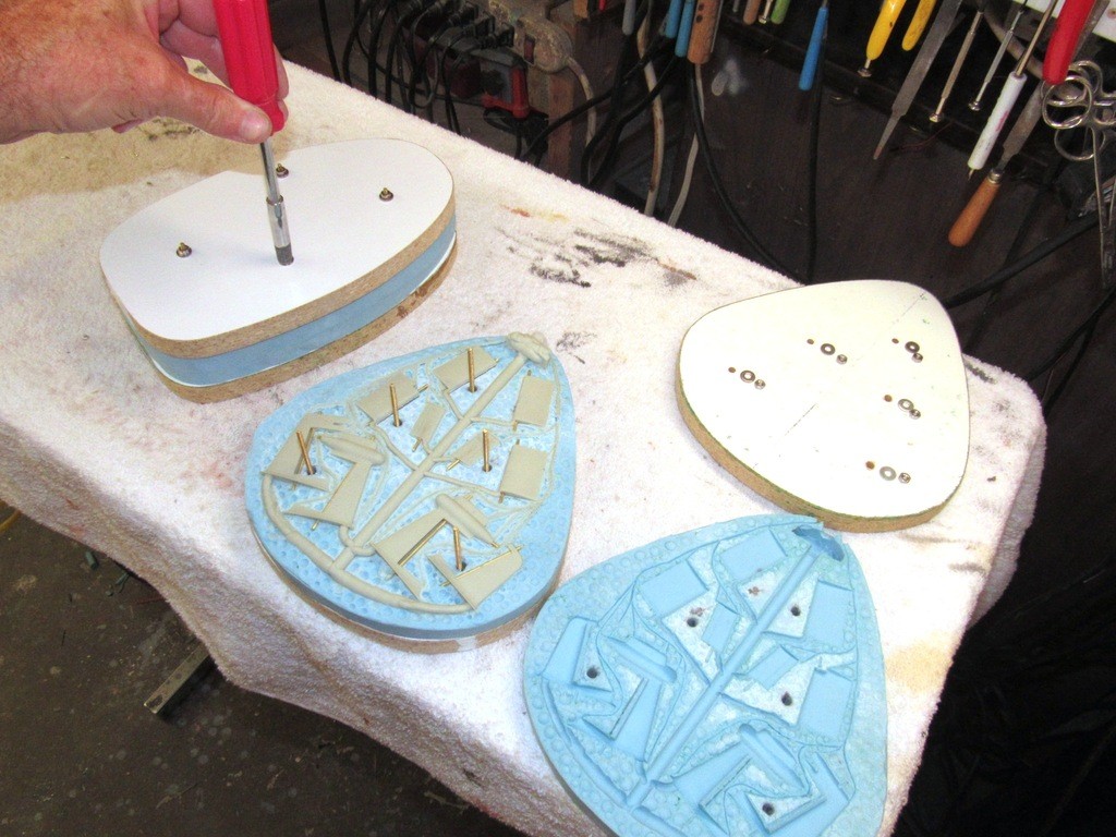
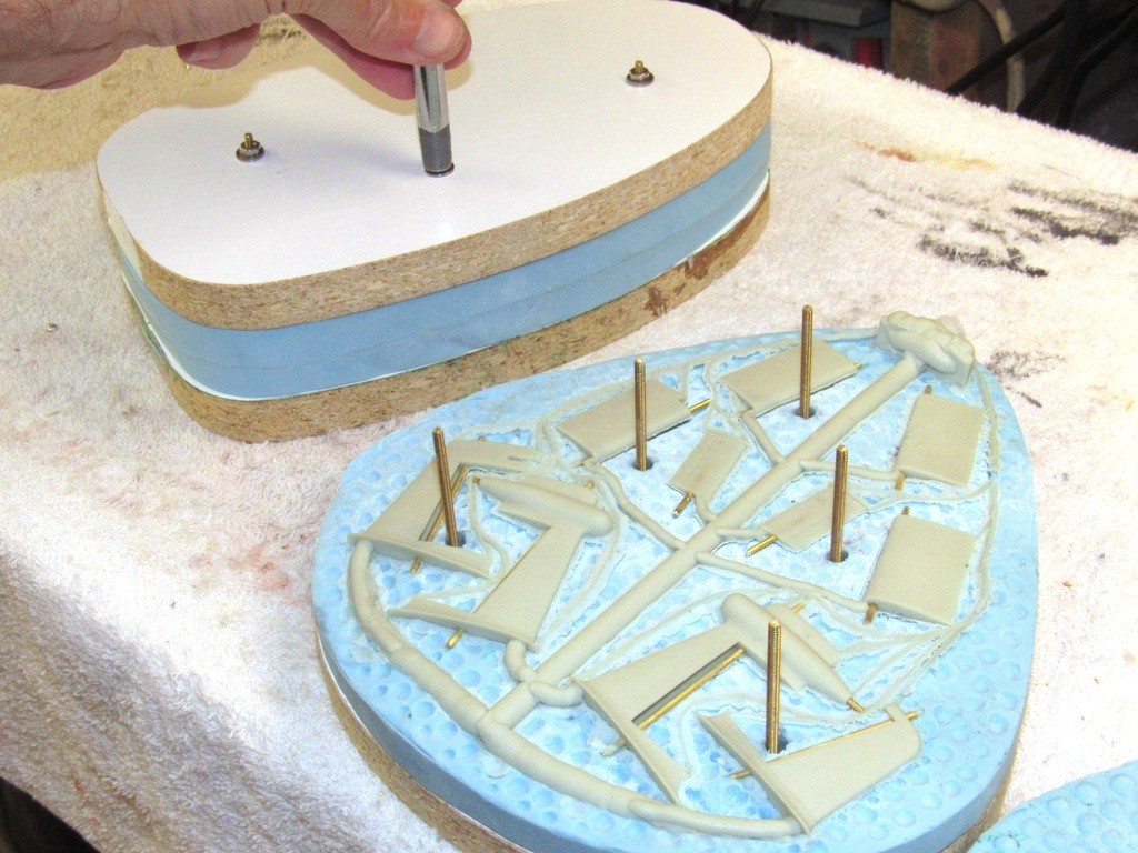
                        Even with all those rubber-bands used to clamp the tool halves together I still found too much flash around the cast parts. So, I abandoned the rubber-bands in favor of a stud-and-nut clamping arrangement. Note that the studs pass through holes punched into the unused portions of tool. Location of each stud determined by examination of the rubber-band secured parts, placing a stud where the flash was the worst. Though this method of tool clamping is a bit involved to establish, the actual production work goes much faster than if rubber-bands were employed. A good investment of time and effort for tools that will see significant production runs.


                        This is the first shot using the stud-and-nut clamping arrangement. Note the absence of excessive flash around the cast resin parts. Brass rod mandrels were installed before casting to give form to the bores within the stabilizer and control surface parts.


                        The casting on the left, done with the stud-and nut clamps has significantly less flash around the parts, runners, and vent channels. Note the excessive flash on the casting on the right, clamped with rubber-bands. Minimizing flash produces parts that are easier to clean and are more dimensionally faithful to the masters than parts cast in a leaky tool.


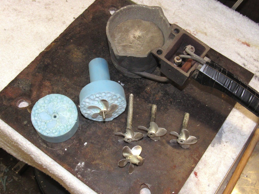
                        The same BJB, TC-5050 RTV silicon rubber I use to make tools for resin casting is also tolerant of the heat involved with low-temperature metal casting. Here that same type rubber is used to make the tool that produces the white-metal propellers and small detail parts.


                        Who is John Galt?

                        Comment

                        • george
                          Captain
                          • Dec 2010
                          • 727

                          #72
                          Hello Sir, is it now time to contact you privately to arrange getting a up grade set from you? Please let me / us know, Thank you
                          George

                          Comment

                          • He Who Shall Not Be Named
                            Moderator
                            • Aug 2008
                            • 12253

                            #73
                            Originally posted by george
                            Hello Sir, is it now time to contact you privately to arrange getting a up grade set from you? Please let me / us know, Thank you
                            George
                            Give me your mailing address. dmeriman@aol.com

                            David
                            Who is John Galt?

                            Comment

                            • george
                              Captain
                              • Dec 2010
                              • 727

                              #74
                              Email has been sent. Thank you sir for your Time with this.
                              George T

                              Comment

                              • He Who Shall Not Be Named
                                Moderator
                                • Aug 2008
                                • 12253

                                #75

                                Now that the tooling for all the cast resin parts is done and I’ve got some good castings from them it’s come time to complete all the masters needed to produce the spin-casting tool from which the white-metal detail pieces will be produced.

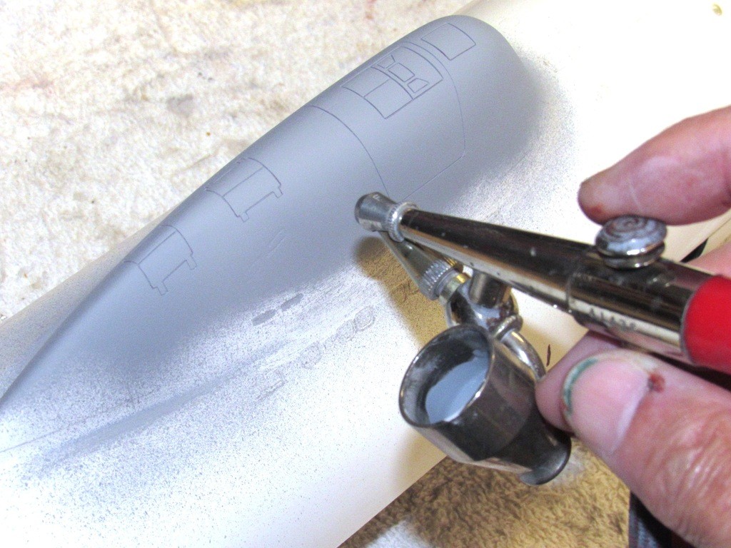
                                In support of those tasks I’ve spent the last few days scribing in the engraved lines representing the hatches atop the sail used to fair over the retracted radar-ECM, DF, scope, and bridge wells. While at it I also engraved the outline of the escape-pod break between its fairing and sail.

                                Capturing the compound curves unique to each station, I laid up a thin-walled GRP laminate. These blanks capturing the engraved lines, denoting where each hatch would be cut away from the surrounding GRP material.
                                The dead-light openings where also punched out on the bridge wind-shield.

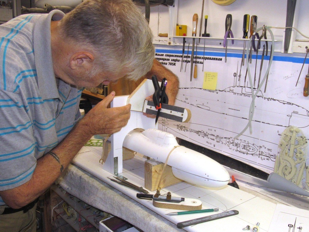
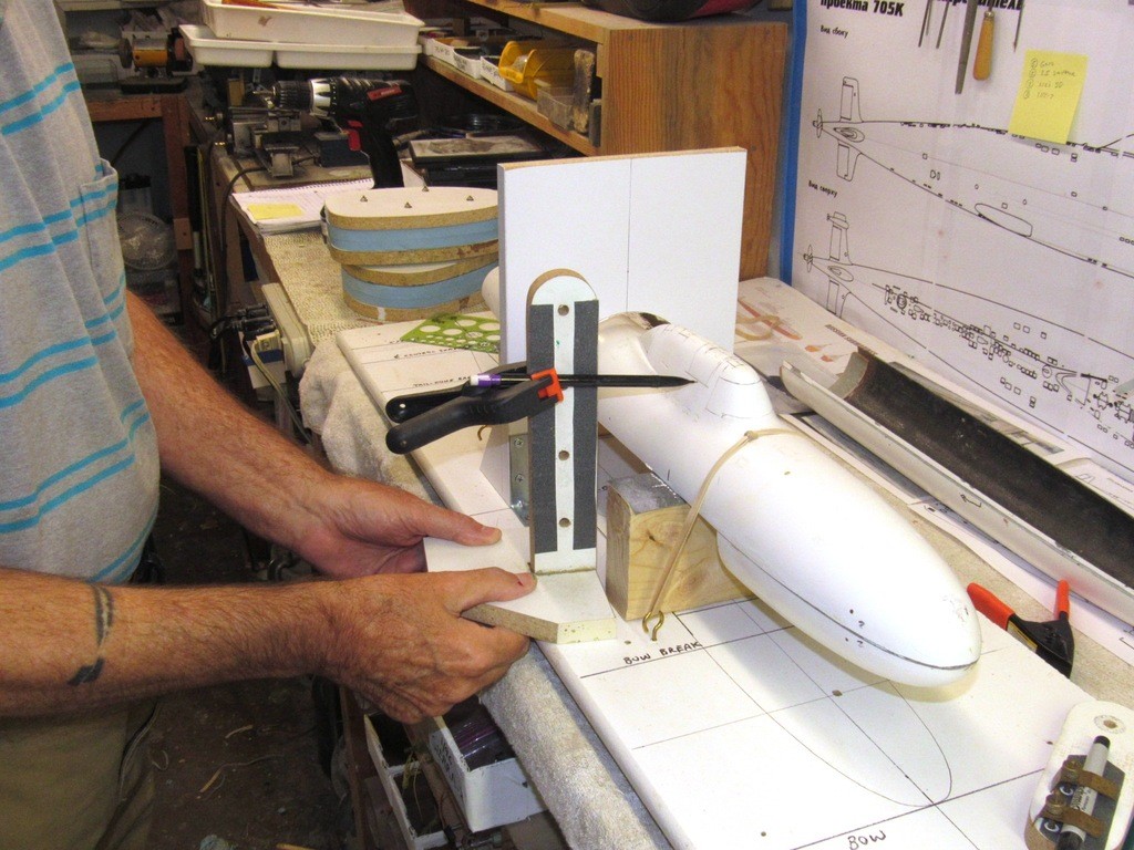
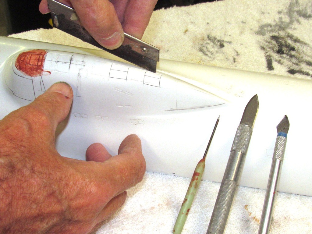
                                But, first, I had to mark off the radial, horizontal, and oblique lines that defined the hatches and escape pod fairing outlines with a pencil – these lines guiding me as I scribed in the hatch and fairing outlines. To achieve symmetry I worked a waterline tool off the vertical and horizontal datum planes established by a holding fixture.

                                Radial lines were achieved by sliding the waterline marking tool along a vertical fence whose face is oriented perpendicular to the models longitudinal axis. Setting the distance of the pencil lead from the face of the fence denoted the radial edges of a hatch as well as its pivot-pin extensions.


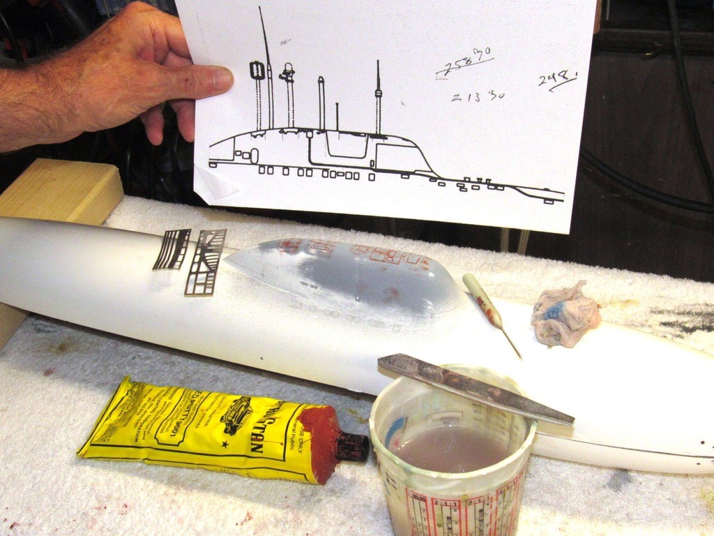
                                Horizontal lines were marked using the flat surface of the holding fixture as the horizontal reference plane. The height, length and position of each horizontal, vertical and oblique line lofted off the 1/96 plan you see mounted on the wall.


                                The gel-coat on this models GRP hull was a joy to work with: hard enough to tolerate drilling and cutting without gumming up, yet soft enough to permit easy scribing with saw tip, knife, and scribe. First I cut in the straight radial, horizontal and oblique lines. Then the more exacting work with knife and scribe to gouge out the hinge pivot-pin extensions and bridge deadlight outlines. One is advised to abstain from caffeine drinks prior to this type work.

                                Note the tool to the extreme right: A small piece of razor-saw has been chucked up in a standard X-Acto knife handle. This tool gives me the ability to cut a straight or slightly curved engraved line without aid of stencil or straight-edge -- very useful in some situations, like those little pivot-pin extensions at the bottom edge of the two mast hatches.


                                Documentation is everything! But only trust photos of the actual prototype. Plans (orthographic, isometric, and scrap-views) are generated by humans and are subject to error. However, photographs don’t lie or are subject to accidental error. Even source documents, such as Ships General Arrangement and Docking plans have the occasional dimensional or form error … and don’t get me started on the all-too-often plan-profile-section paradoxes discovered when attempting to generate waterlines and buttock lines.

                                Note the use of commercial scribing stencils. I made good use of these as I cut in the tiny pivot-pin extensions and deadlight outlines.


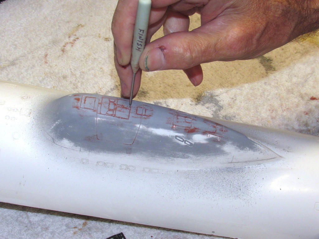
                                Overstrikes, cheat-lines, corrected lines, and other boo-boos were filled with Nitro-Stan putty and sanded smooth – this step repeated many times until only the desired engraved lines remained atop the sail. It’s vital that before the putty dried the desired engraved lines are chased out with a scribing tool to preserve the work.

                                The ‘finishing’ scribing tool differs from the first-pass tool in that it features a rounded tip and a shank a few thousand’s of an inch smaller in diameter than the first-pass tool. It’s the job of the finishing scribe to chase out filler and sanding dust, not to continue to cut depth or width of the engraved line.


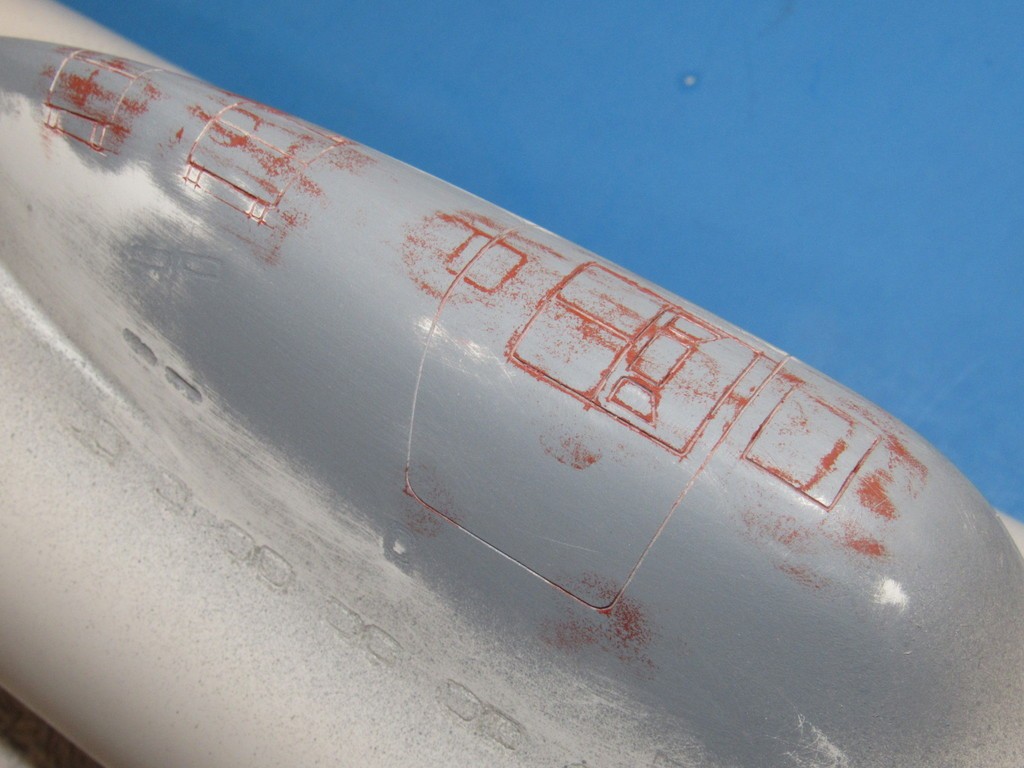
                                At this point the work looks like hell.

                                The long oblique lines on the sides and running around the top of the sail represents the break between the sail proper and the plating that fairs beneath it a deployable ‘rescue chamber’.

                                (In the event the crew has to abandon the sunken submarine they would all jam up into this pressure sphere, located beneath the bridge, button it up, and release it from the submarine. It would then float up to the surface where the men would transfer to inflatable rafts and await rescue. The system actually … kind of … worked when a Soviet MIKE class submarine grounded after a fire and subsequent sinking.)


                                A quick shot of primer gray reveals an acceptable looking engraving job.

                                The biggest sin with this kit is the awful engraved detailing atop the hull and sail. Misshapen, out-of-place, and not conforming to any reliable documents I have been able to unearth – and I don’t think anyone this side of the Malachite Design Bureau has more dope on this boat than me!

                                The only trustworthy original engraving on this kits hull is the torpedo tube shutter doors, and those will have to be cleaned up and deepened. Ah! The Joy of kit assembly!


                                Now, this is where I go bat-**** (yet again!) with a project that was only supposed to take a few weeks of my precious time. Your idiot author decided to produce two sets of auxiliary hatches, one set representing closed hatchs (to cover open wells and/or open bridge cockpit); and another set of port and starboard hatch halves to be mounted on the model to compliment the display of masts and scopes in the raised position, and an opened bridge well.

                                The masters of the off-model hatches would be GRP, that material chosen because of its ability to faithfully capture, exactly, the compound curves of the hatches; and to render strong, thin-walled structures. Those intermediate masters would be used to make an intermediate tool from which production masters would be produced – detailed inside and out and split into their respective parts. Only then would the two sets of hatches we employed to make the production spin-casting tool from which all the detailed small bits of the display would be manufactured from white-metal (95% Tin, 5% Antimony).

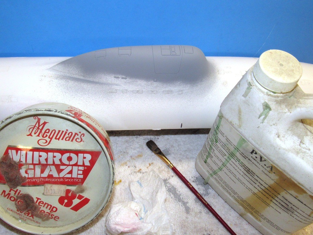
                                But, before all that, I had to lay down a protective barrier of wax and poly-vinyl alcohol over the top of the sail. The same part-release system as would be used for your typical hard-shell GRP part lay-up. Old school… by cracky!


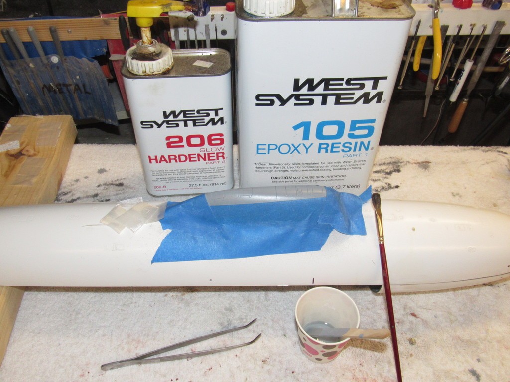
                                To keep any of the laminating resin from running down onto the hull I laid down masking tape to the sides of the sail. The part-release system applied, some light-weight glass cloth squares cut out and set aside for the lay-up job.


                                Who is John Galt?

                                Comment

                                Working...