Yeah, I've seen some of his stuff. Informative, but he should stick with his rating. He can talk with confidence about TMA, and sonar systems. But torpedo homing methodology is sometimes sketchy. I don't trust gamers.
Jive Turkey is a Norman Polmar of the Internet type. Generally informative, but definitely not the fact-checker technical history slueth of a Norman Friedman.
David
-
Well I’ve only met Ellie once, but I know better than to argue there!
Lecturer is a former career submariner who has a professional YouTube channel under the username Jive Turkey. Great resource for been there / done that commentary & analysis - that he can discuss in a public forum. Smart guy, but certainly not above a slip of the tongue.Leave a comment:
-
-
Oh really? I heard a lecture that claimed ALFA's limber holes were made without shutters. The presenter must've had his facts mixed up. Honestly that didn't make a lot of sense given boats like the SIERRA and others had working shutter doors. Thx for clarifying.Leave a comment:
-
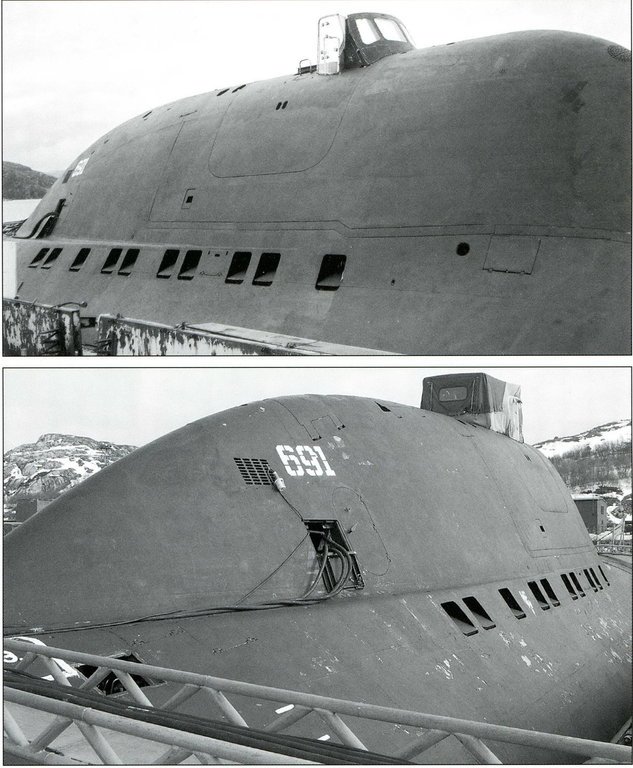
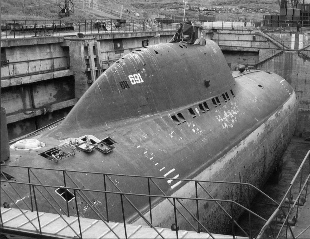
Those 'open' limber holes had remote shutters that closed once the annular space between the hulls was full of water. The Malachite Design Bureau was cognizant of that potential noise source and worked hard to mitigate it. You see that feature on all their boats.
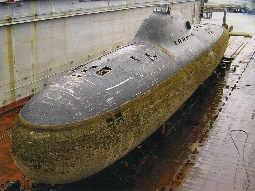
Complicated, expensive, and a density that made the adoption of the strong yet light-of-weight Titanium a necessity. Obviously the Russian naval architects have a better grasp of the weight-displacement problem than todays Spaniards.
DavidLeave a comment:
-
“Engineering says 105% on the reactor possible, but not recommended...”
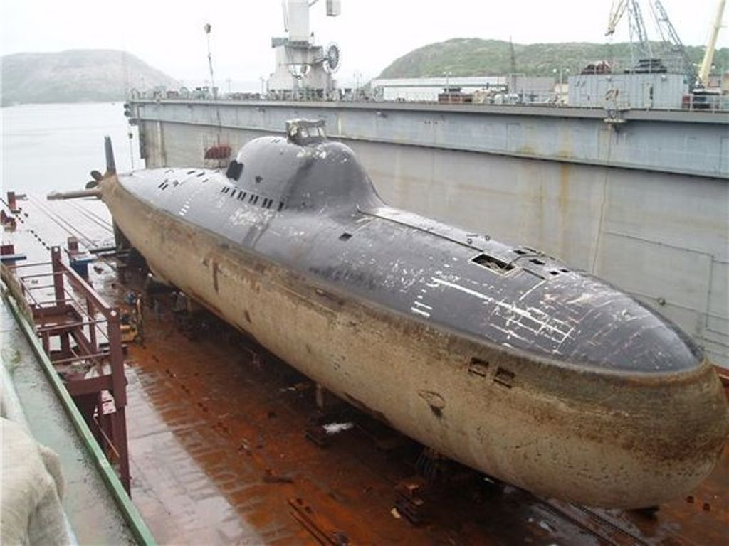
I know it took the Soviets a lot longer to figure out that stealth > speed, but I am astonished that those lumber holes remain open when the boat is submerged. At 42kn, that thing must have been loud enough to hear through the water without the need for a sonar! Subtle & sneaky as a g*****ned freight train.
In all seriousness though, what an odd & complicated little boat she was.Leave a comment:
-
I finally finished all the topside scribing. (Well, almost, I still have to re-establish the port side flat of the after escape trunk hatch). However, I still have to identify the flood-drain holes beneath the hull. Once I’ve denoted the location and shape of those holes I’ll open them up with the aid of rotary burr and hand-files. And the two secondary loop scoops have to be glued to the lower hull and filleted in.
I’ve established the locations of the bow plane operating shafts, and installed a well for the emergency marker buoy. Things are rolling along at a good pace.
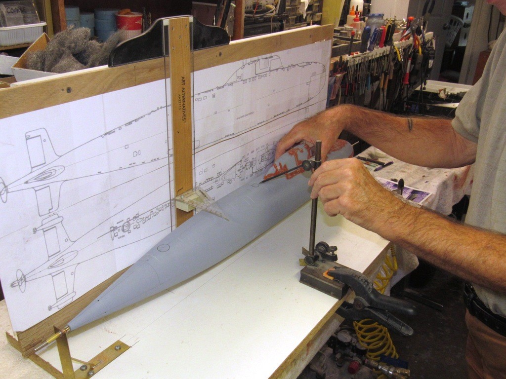
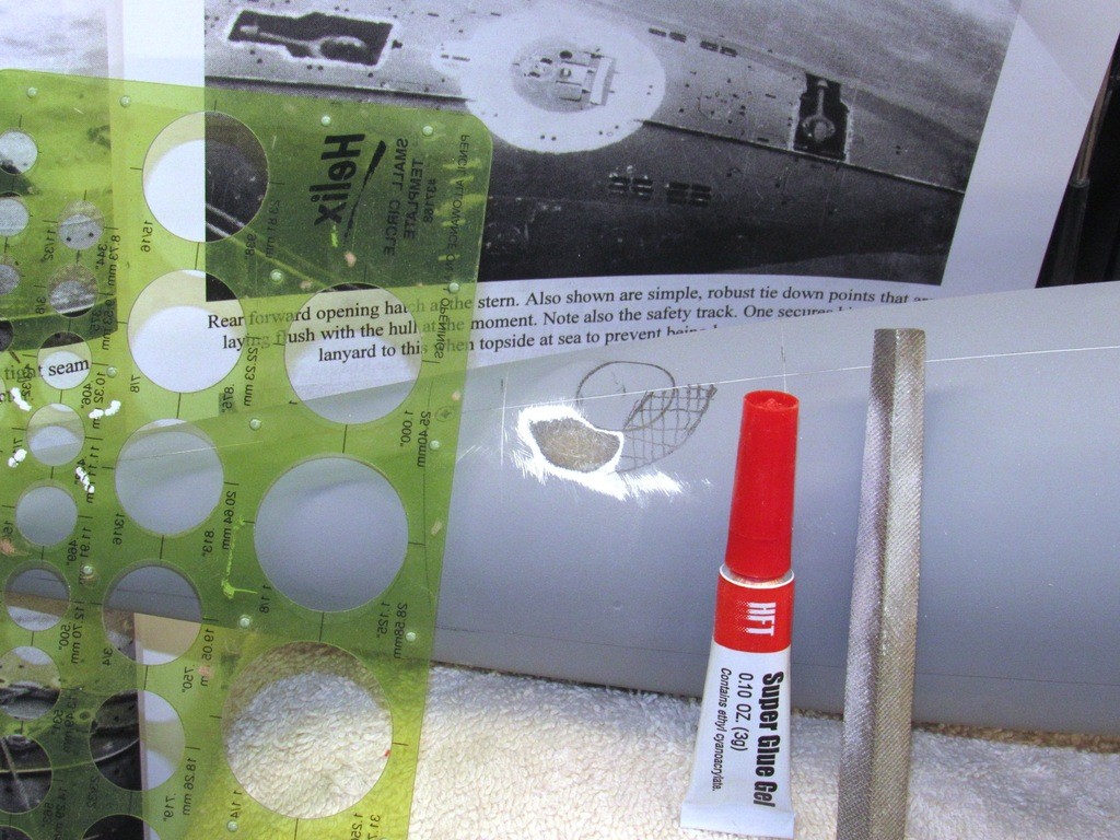
Some old business: I promised to show the modified T-square I use to loft the position of an item on the plan to the physical model with reasonable ease and accuracy. The picture should be self-explanatory.
I mocked up the bow plane arrangement. As is my want, I endeavor to make the bow/sail planes on my r/c submarines practical. Such is the case with this little 1/96 ALFA class submarine. A unique feature of this class of submarine was the height stagger between the two planes (to obtain the internal clearance of the retract mechanism when the planes are housed in the ‘retracted’ position). A unique feature, I wanted to show-case; a little chaos is a good thing every now and then.
An example of intentional asymmetry on the ALFA design is the vertically displaced distancing of the two bow planes. Note how they are staggered in relation to each other. As these retractable control surfaces slide in and out from the ‘retracted’ and ‘deployed’ positions there was not enough space between them, when retracted, to position them on the same vertical plane. Malachite’s solution was to stagger them (one above the other) to get these long-of-span control surfaces to fully retract when stowed.
I assume that the bow planes were only rigged out when operating at periscope depth or during evasive maneuvers where rapid depth change rates were required. Otherwise, these dragy control surfaces would have been neatly tucked into the hull. After all, the ALFA’s were the Soviet’s second fastest combatant type submarine ever in service, so everything that could be done to make these boats ‘slick’ was done. You don’t need bow planes when you’re booking along on a flank bell at transit depth.
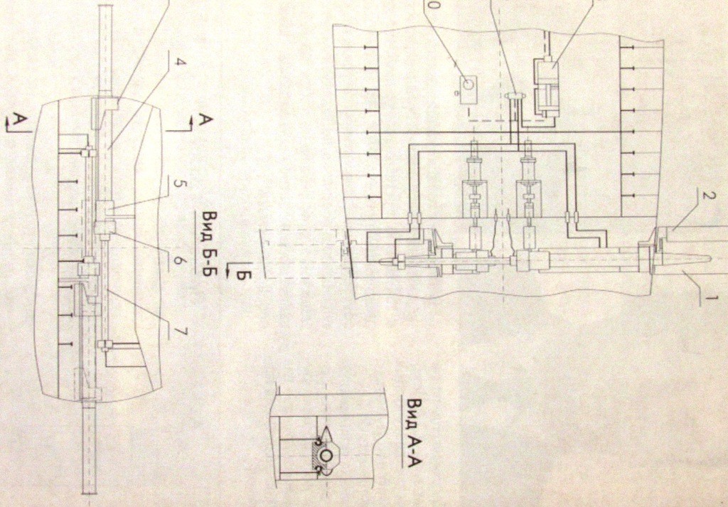
Because the two control surfaces don’t share the same plane, I cannot use a single operating shaft between the two bow planes. I’ll have to provide each with its own bearing tube within the hull and interconnect the two operating shafts (one per plane) with a flexible coupler, likely a short length of flexible rubber tubing – an arrangement that will permit both planes to rotate in unison off of one bell-crank.
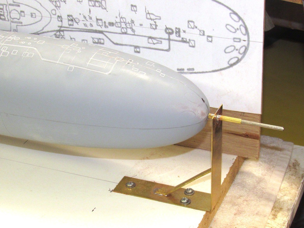
To insure that the internal bow plane operating shaft bearing tubes are positioned parallel with one another I’ve extended a temporary operating shaft through the hull with a bit of it projecting through the opposing side of the hull. Later, these extended, temporary operating shafts will jig the bearing tubes in correct position as I epoxy them within the hull.
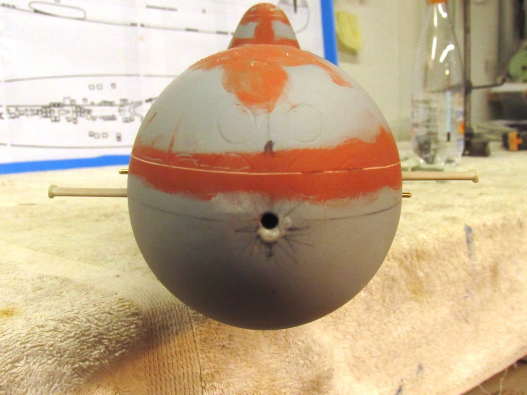
The escape buoy sits in a well. I turned a well from some RenShape and CA’ed it into a hole I punched atop the hull, just aft of the sail.
I could have elected to simply scribe a circle to represent the demarcation between circular buoy and deck, but I’ve been giving some thought of making a practical buoy – as advocated by Manfred Reusing who has been outfitting his scale r/c submarines with such a sub-system for decades -- never hurts to have a back-up to get a disabled, sunken model submarine back to the surface!
A possibility, later, taking Manfred’s lead, is to outfit the model with a practical float that would be tethered to the model through a long fishing-line down-haul cable. The buoy released to rise to the surface once a water-soluble retainer had been exposed to water for a significant amount of time (a piece of spaghetti or a Tic-Tac).

There were only three significant errors I’ve found on the hull: the Sail is too short (but to be honest, this model might be representing the prototype which reportedly had a sail of different contours than the production boats); the torpedo tube shutter doors are to low and too large of diameter; and the location of the after escape trunk hatch flat is too far aft.
Here I’ve – for the sake of illustration – only worked one-half of the after escape trunk hatch flat. First I used a course file to shave down the after flat (the bare GRP exposed) to the normal contour of the hull, and used CA and baking soda to build up a mass forward (where the penciled hash-marks is) that is then filed to a new flat. The port side eventually got the same treatment.
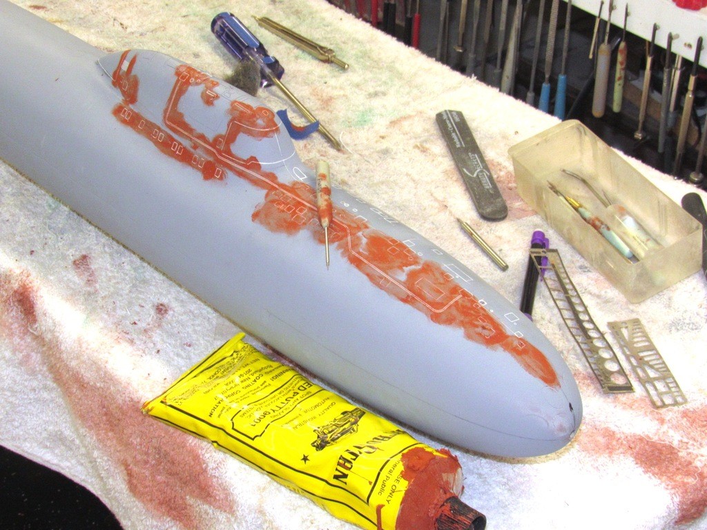
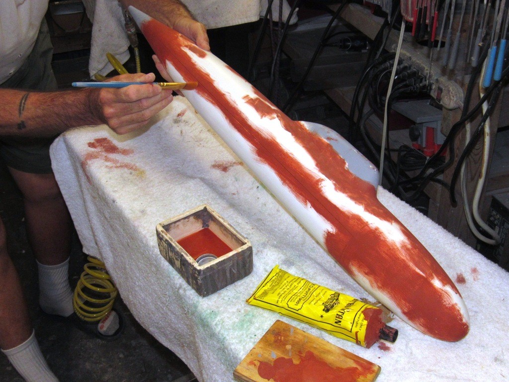
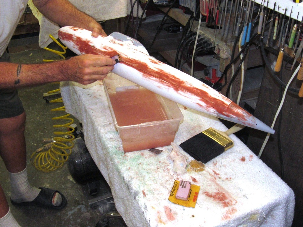
After scribing in the deck and sail details I applied touch-up putty to fill datum lines, cheat-lines, and flawed engraving work. The putty was pushed into the work with a finger, after which I quickly chased out the still wet putty from the engraved items I wanted to retain with the finishing scribe.
The thinly applied putty dries quickly, and those areas were wet-sanded with #600 backed by a semi-stiff sanding block. You can make how the red colored filler fills the flaws.
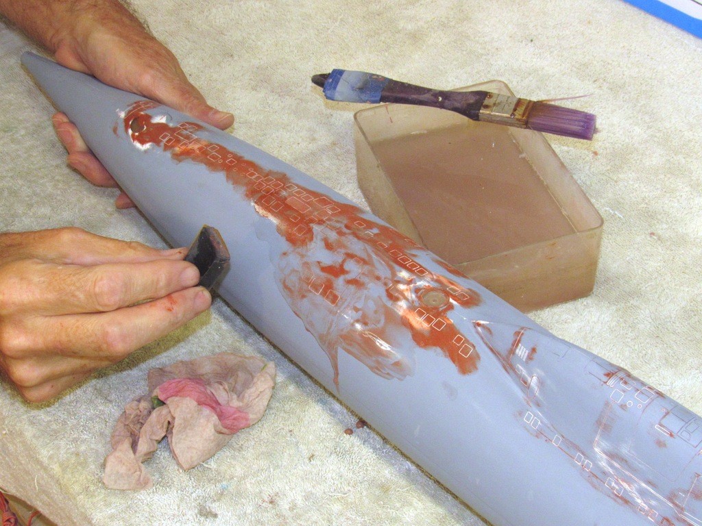
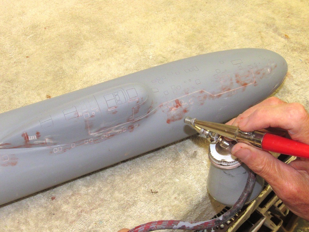
I’ve already laid down primer to the port side, and you can just make out some of the engraved items. The starboard side is about to get its coat of primer.
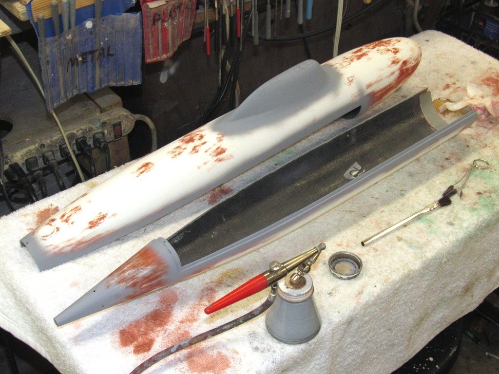
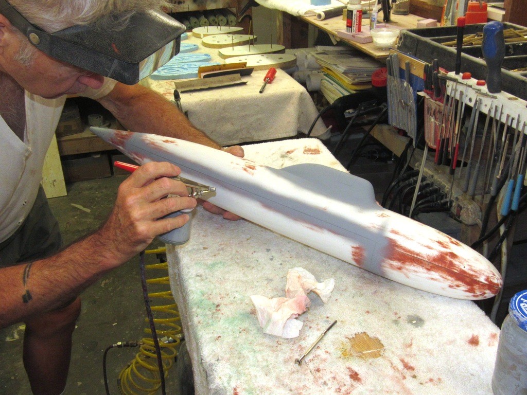
Unaddressed flaws, missed or inadequately filled by the putty, are revealed by the gray primer. Such problem areas were addressed with further scribing and/or putty to put the work right, followed by a touch-up blast of primer. This process repeated till things are near perfect.
Leave a comment:
-
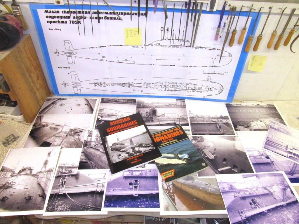
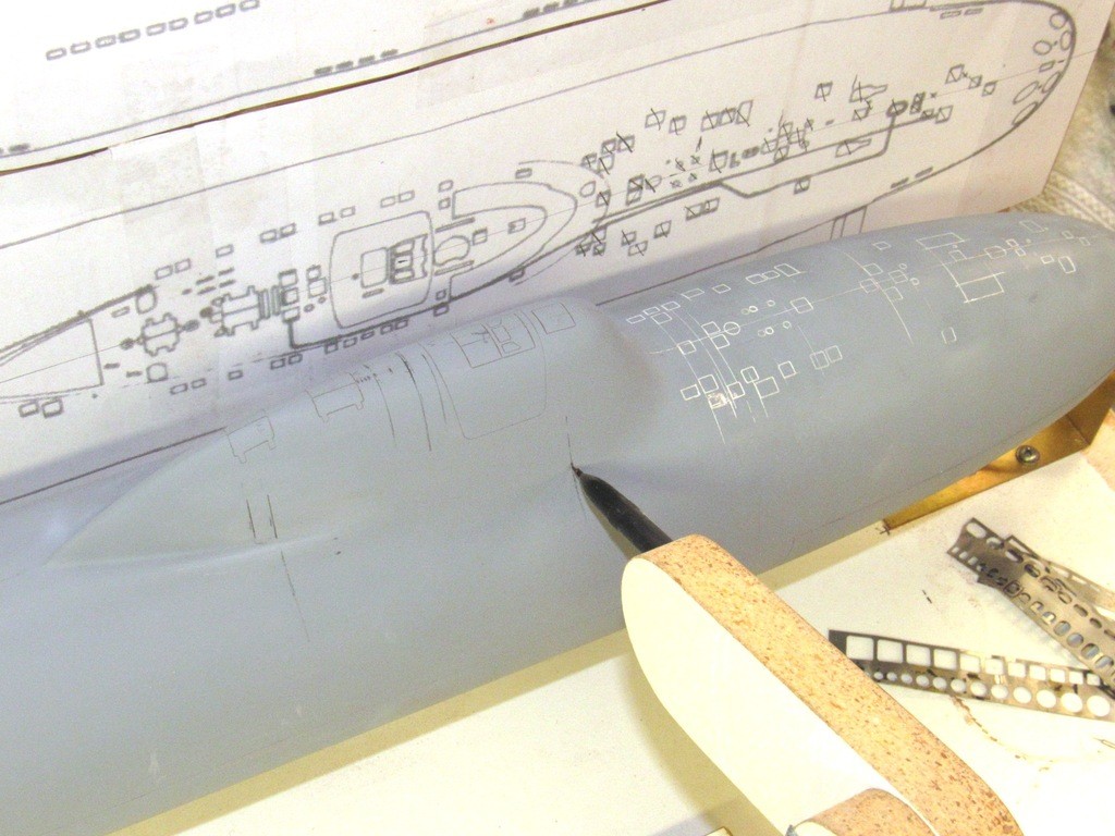
The hull finally in primer gray and most of the body work out of the way. The time came to scribe in all the deck lockers, hatches, limber hole outlines, emergency towing pendant troughs, bollard tops, escape hatch, torpedo tube shutter doors, sonar window outlines, staggered bow plane operating shaft locations, flood-drain holes, limber holes, secondary loop condenser scoop locations, and other markings on the hull.
Supplementing the drawings were the photos and books I’ve accumulated over the years on the subject. You can never have too much information! The key document for the scribing is the plan and profile orthographic projections of the ALFA class submarine. However, no such document is perfect; there are always differences between specific units of the class. But, as a ‘generic’ ALFA, these drawings were most representative of prototype. I went with them with little modification.
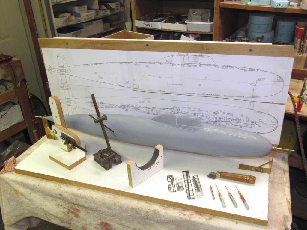
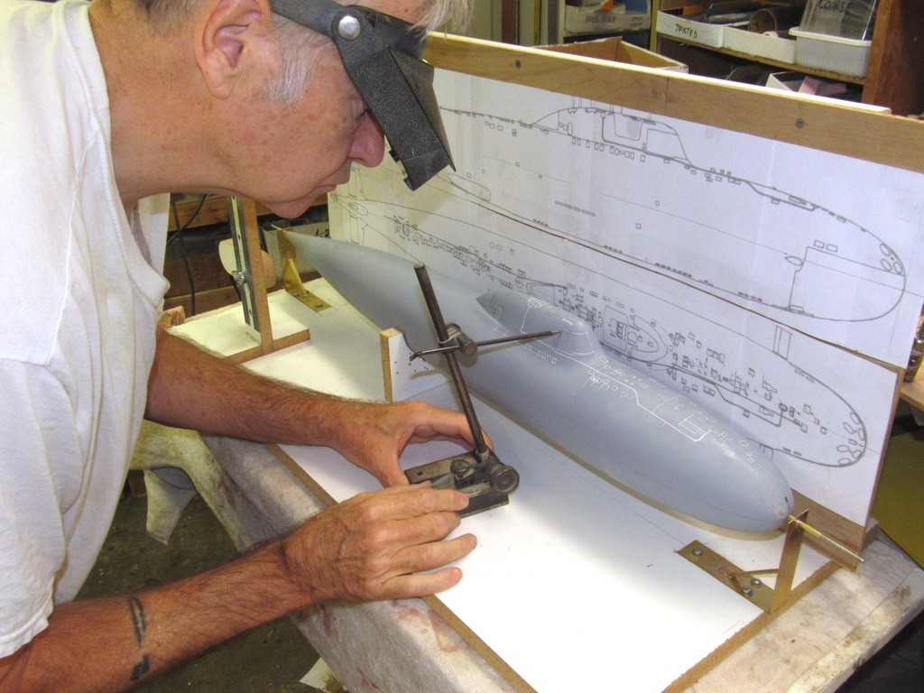
Lay-out is the process of transposing a two-dimensional depiction (ideally orthographic drawings) of form to a three dimensional object. Aiding me in marking out the hull with the proper location and form of the engraved items I employed a custom built marking jig. This jig, outfitted with an orthographic two-view drawing of the ALFA, insures accurate lay-out from plan to work; off these drawings, using this jig, I lofted the shapes from plans to model.
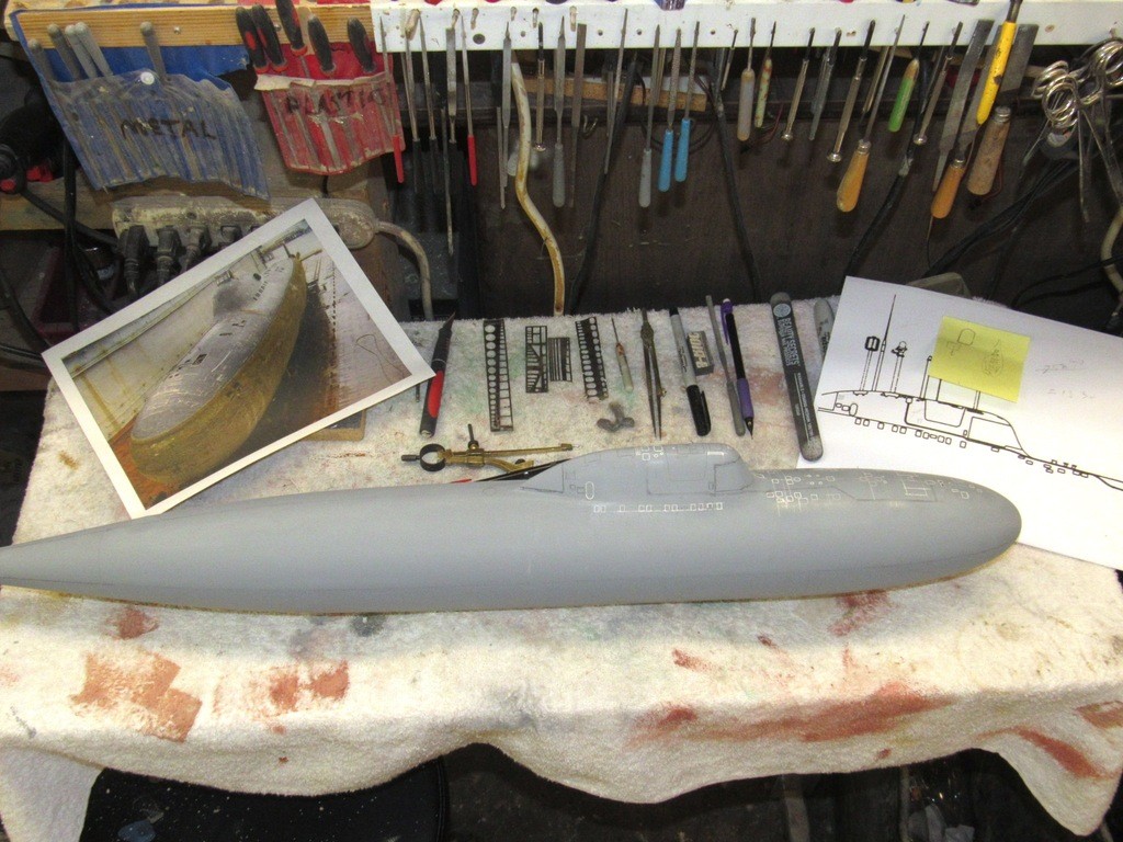
On the bed of the marking jig bed, left-to-right: pencil loaded waterline marking tool; a proper Machinist’s surface gauge; a crutch used to secure the model against rotation; most of the commercially available, stainless steel scribing stencils I used on this job; and an array of engraving tools.
Note how the model is suspended by the fore and aft suspension bearings mounted to the bed of the jig.
And a word about the Scale Shipyard 1/96 ALFA model kit: I’ve found the hull to be of exceptional quality, the master from which its tooling was produced was crafted extremely well -- things are perfectly symmetrical; the glass lay-up of the GRP hull halves was well done; and the gel-coat both well bonded to the underlying glass and soft enough to be scribed easily without chipping. This hull kit is highly recommended!
The hull is suspended with its longitudinal axis parallel to the bed of the marking jig. The work is free to rotate, but not move axially. The two suspension bearings – each equipped with a 1/8” diameter stainless steel pin that sleeves into a bearing tube – at each end of the jigs bed suspend the hull during the lay-out process. The stern of the model already had a centered 1/8” bore to accommodate the propeller shaft so that was already taken care off. That left me to ascertain the center at the bow and drill a temporary 1/8” bore there to accommodate the forward suspension bearing pin.
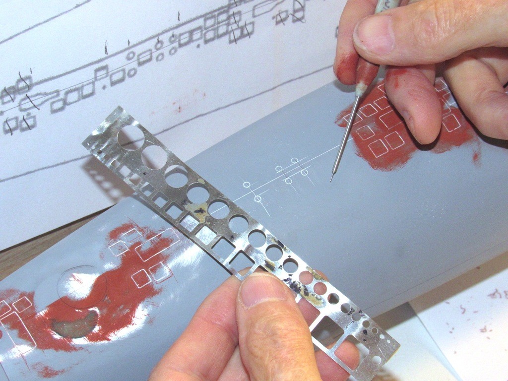
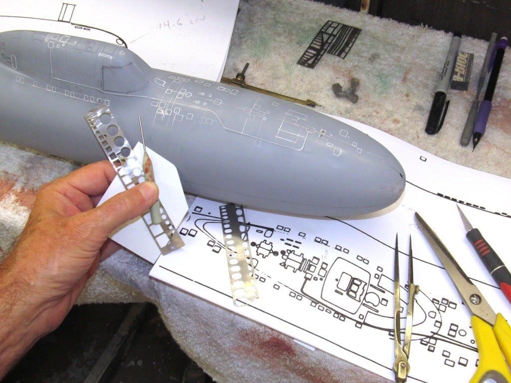
Not shown in this installment was the tool used, a modified T-square, to transfer the location of a scribed item from the plan to the model – I’ll detail that process next installment. Here I’m rotating the work to pencil-mark radial lines. Note that the base of the pencil loaded surface gauge (waterline marking tool) is clamped to the bed of the marking jig so it cannot move axially. The bolt holding the swing-arm of the tool has been loosened enough for the arm to droop of its own weight, but the bolt is just tight enough to prevent any left-right motion of the arm.
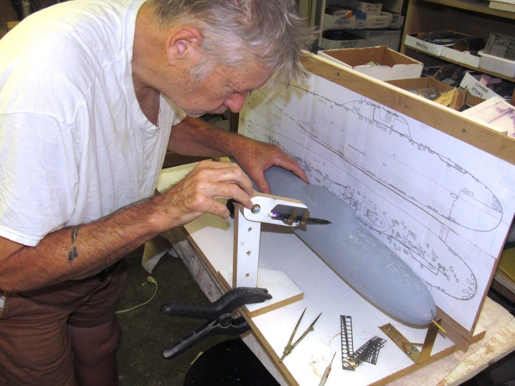
Here I’m using the pencil loaded waterline marking tool to mark off a radial line -- that line will later guide me as I scribe the vertical element of the sail forward sonar window outline. All scribing is done off-jig. The pencil point kept on the work by the weight of the swing-arm that mounts the pencil. As the work is rotated, the pencil point bobs up and down on the surface of the work, marking off a perfect radial line, no matter the complexity of the compound curve under the pencil point.
I made use of commercial and custom made scribing stencils to guide the scribing tool. All scribing was done off the mark-off jig because, had I done that work on the jig, the pressure applied as I cut into the gel-coat would have been too much for the two bearing points to support without damaging the jig. It was an easy and quick process to slide the two 1/8” support pins at each end of the model out, and transport the model to a work station where I could more easily apply stencil and get on with the engraving process.
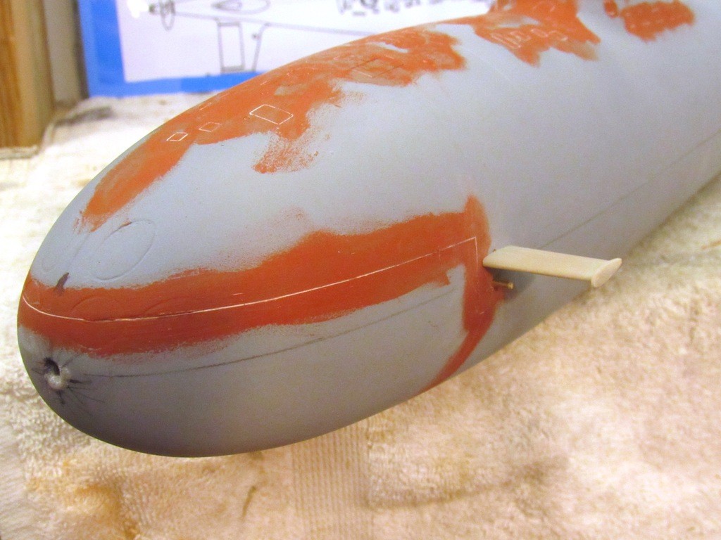
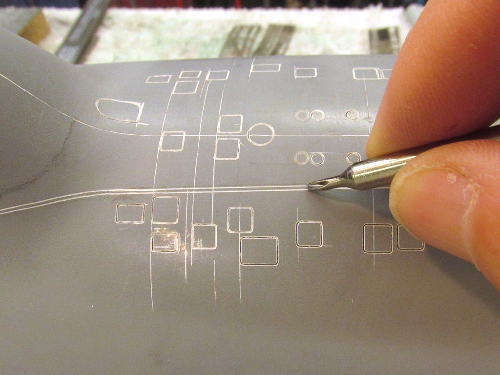
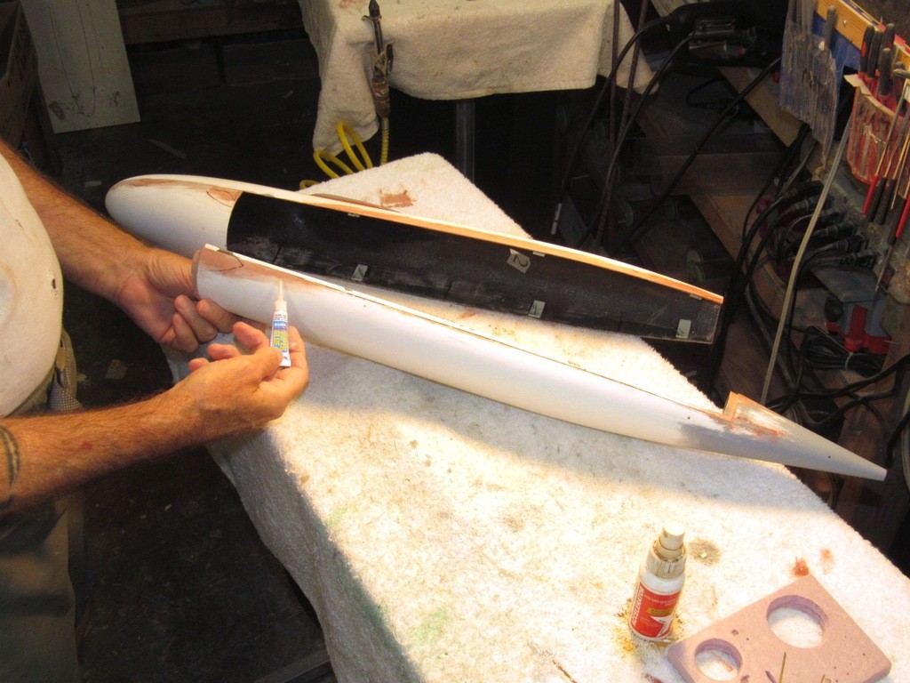
I needed two closely spaced, parallel running engraved lines leading from atop the sail to well forward on the bow. Those parallel engraved lines taking a rather torturous route, but well documented by pictures and plans. I employed a standard scribing tool and a variety of straight-edges, commercial, and hand-made stencils to achieve the first engraved line.
I then used my two-point engraving tool (typically used to form American safety-track engraved lines) to lay down the second engraved line, parallel to the first.
No, the two parallel engraved lines are not safety track – the Soviets …err … Russian’s employ raised pipe for their safety tracks – these lines represent the edges of a fairing strip covering the entrenched ‘emergency towing pendant’.
One of the two cutting edges of the tool follows the first engraved line. The tool is then carefully dragged along; its other cutting edge engraved the second line. Multiple light pressure passes gets the job done. The result is two perfectly distanced parallel engraved lines of uniform depth.
Yes, I can see that the first pass of the scribing tools looks like ****! Patience! After some putty work and corrective work with knife and engraving tool, I’ll have it all pretty, just like the real boats. What you see on display here is the dark underbelly of lay-out and preliminary engraving work: over-strikes, missed passes, wrong locations, chipped gel-coat, and too many cups of coffee on an empty stomach!
The hull held fast against rotating or moving axially by the crutch (seen under the hull, bearing against the bed of the marking jig) I set the height of the Machinist’s surface gauge tip to where I needed a horizontally running engraved line and carefully slid the tool along the surface of the marking jig till I had the required line. This engraving is not done with one heavy pass – that would screw things up by chipping gel-coat and likely causing the model to shift under the drag. No, this work is done by several, light pressure passes of the tool over the work.
First application of air-dry lacquer bases, touch-up putty – good old Nitro-Stan! This is rubbed into the engravings, and the finishing scribe used to chase out the putty from the engravings. This is how I fill all those over-strikes and other boo-boo’s!
Me be much smart!
Leave a comment:
-
-
I took about ten days off from the ALFA project to participate in the big r/c submarine fun-run in Connecticut, at the Groton submarine base North Lake. Eric Bertelsen was there, he’s the guy behind Homeport Models, http://www.homeportmodels.com/ He’s also assembling a Scale Shipyard 1/96 ALFA kit – actually, two of them!
At the event Eric and I comparing notes on how we’re getting our respective projects into presentable shape.
After a delightful weekend it was time for the long trip back to Virginia Beach and back to work.
I soldered four studs to the sides of the brass ECM-radar antenna master. These studs support the two rectangular plates that comprise one element of this multi-purpose antenna array. Here I’m centering the work after shifting from a three to a four-jaw chuck.
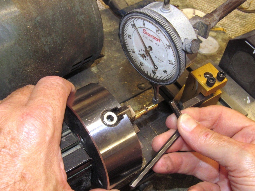
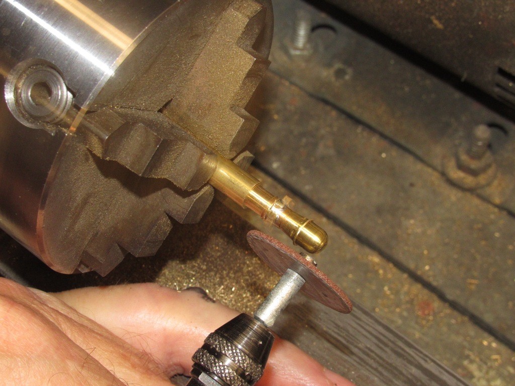
The four antenna support lugs that radiate out from the body of the ECM-radar master were pinned and soldered in place, so their attachment was robust enough for me to grind their outboard ends to a uniform height by spinning the work in the lathe as I lightly applied the rotating face of a carbide cut-off wheel to them, as you see here.
I put the detailed metal work aside for a bit and got hot on the ALFA’s hull.
The glass work is very good on this one: not too thick, not too thin, this hull having a nominal wall thickness of .095”. And the white gel-coat is thick, tightly bonded to the glass under it, and flaw free – perfect for scribing.
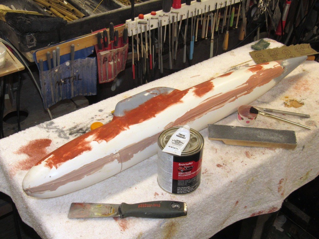
I started tightening up the radial and longitudinal seams between the upper and lower hull halves with Bondo, but only after thoroughly sanding all surfaces to insure all contaminates were gone and to produce a scratch surface to enhance adhesion of filler, putty and primer to the gel-coat.
I cut the Bondo with some lacquer thinner to make it a bit more ‘runny’. Just a matter of preference – I find it easier to maneuver the catalyzed filler with a putty-knife, and the thinned filler seems to cure quicker than the thicker mix as it comes from the can.
Note that I smear the filler over the longitudinal and radial seams. A shape X-Acto blade must be used to open up those seams again right after trolling on the filler, before it starts to harden, or you’ll have a devil of a time separating the two hull halves later.
A big, heavy rasp file was used to knock down the Bondo filler once it had cured to the ‘green’ state: not yet too hard, but hard enough to stick to the work and be easily abraded away with the tool. The weight of the file -- specifically its inertia as it’s pushed over the work -- helps it to maintain a constant height of cut, maintaining a consistent curvature of the compound curve form of this tear-drop shaped hull. The strokes are both axial and radial of form.
The filing is followed by a hard-block sanding using #200 grit sandpaper.
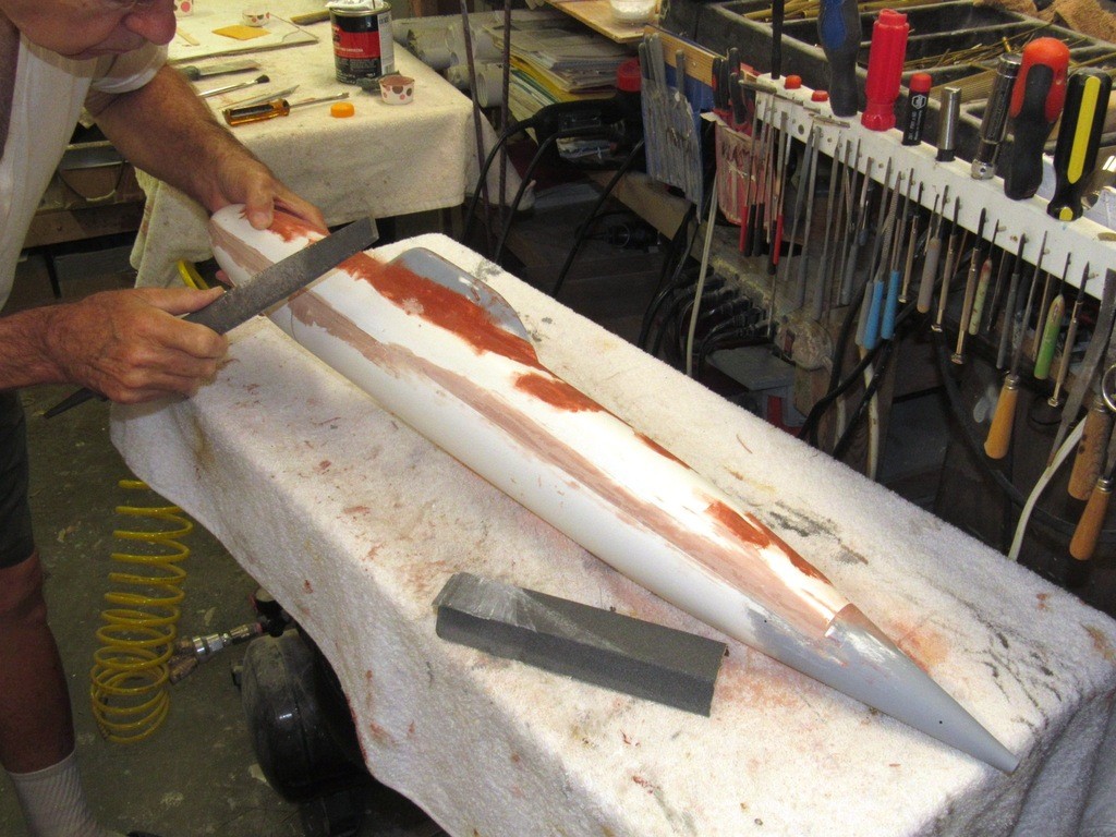
The gross filling and contouring with the Bondo is checked and areas that still required filler were marked and received more Bondo. The touched-up areas then worked with a single-cut file and careful block sanding. This step repeated till the desired contour of the work is achieved. The work is then addressed with a soft-block sanding with #240 grit sandpaper.
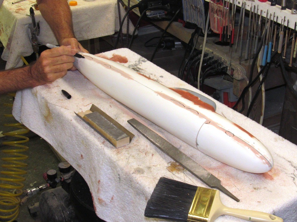
Typically the two-part automotive fillers, like Bondo, cure to a light-weight, permeable substrate that, particularly with models subject to repeated and sustained submersion in water, will absorbed moisture if directly exposed to water. This potential problem is headed off at the pass by skinning the filler with thin formula CA adhesive. This also strengthens and hardens the filler in those areas where it would otherwise be subject to damage such as the edges and corners where the two hull halves join together. The CA cures almost immediately and this ‘skin’ is then lightly sanded with #240 grit sandpaper.
The hull halves are re-assembled and Nitro-Stan air-dry touch-up putty is brushed over the areas that received the filler as well as all seam areas. Of course, right after application, the knife is once again used to open up the seams between the hull halves. As required the putty is cut a bit with lacquer thinner to make it more suitable for brush application.
All putty work is wet sanded with a soft-block. Initially with #240, but shifting to #400 once the majority of the putty is abraded away. The work is rinsed in water, wiped dry and hit with a heat-gun to insure all moisture is driven out. The hull is now ready for the first primer coat.
Automotive acrylic lacquer primer was first sprayed onto the flanges, edges, and corners where the hull halves meet. The sail area was also knocked out while the two halves were separated.
The primer dries almost as fast as you lay it down, so the work goes very quickly. The hull was assembled and the priming continued.
Leave a comment:
-
Dave if every post you've ever made every article you've ever written and published is not stuck into one complete book of modelling (maybe an encyclopedia set) it'll be a lost to the rest of the world.
I am amazed at your attention too detail.
The skill you have amassed and with that the biggest skill is paients too follow through with the precieved finished project too the end.
In the next installment will you grab two cans of Krylon flat black and red oxide primer / paint and finish her off? And of course the use of white out for bird poop for the top rudder?
Rick
Leave a comment:
-
Solid Gold, Gantu. Thank you so much -- just in time for the detail scribing! Which will have to wait till later in the year -- after the Groton event Bob will put me to work on some kit development and SD production work we have to catch up on.
You come up with the most marvelous stuff, sir. I may want to publish some of these -- with your permission of course -- in the WIP. Who do I give picture credit?
DavidLeave a comment:
-
Fascinating. I wondered how you bent up all those DF arms so consistantly. Now I have the answer. Very cool.Leave a comment:


Leave a comment: