-
Along with the lack of info regarding the indexing pin there's also the matter of the absence of the SD unit support saddles. Does one use the kit's existing bulkheads as with the Gato conversion? -
I'm building a VIIC too. The SD came with manifold blocks that look like they adapt to SAS, although I have a tank installed and no float or safety valve apparatus. The middle block now has the induction pipe from sail coming in parallel to the lexan tube, and there is a third manifold block which is simply a right angle turn block which I guess goes somewhere near front of SD(?).
In all of this I'd like to be able to use either tank or SAS, so if there is any positioning of something or addition of something (such as putting a hole in deck under sail such that it won't interfere with the float valve later on) could you state so. And I have the following questions:
1) where do I place the two manifold blocks middle and front(?), ...I'd like to use tank with SAS if desired later- this may make placement of middle manifold block tricky, or at least demand a precise positioning under the sail? About how many inches behind the gas tank valve centerline should I drill the hole in the lexan and mount the middle block?
2) Where does the front block go and what purpose does it serve?
3) I have all the larger upper limber holes cut. Are there some holes I should not cut lower down to avoid weakening the plastic?
4) As observed by OP there is no velcro band supplied. But there is also no indexing pin/hole supplied. How do I position or line up the SD within the hull?
5) What is the 4th "connecting rod" port in aft bulkhead for? The one with a short brass L-shaped rod stuck in it? It has the same seal as the other three ports, but is just below them and in between motors?
Update: Just got done testing the gas/vent valve, all is well there. Had to tighten the tank fill nipple valve, quick tweak. Looks really great, look forward to having three ways to blow! Please let me know about these questions as some are puzzling and others critical to positioning of both SAS and Gas. Thank you again.Leave a comment:
-
-
Just acquired a Revell Type VII myself. Also got the fittings kit.
No dedicated SD or WTC yet but I do have a Seawolf SD unit. Was thinking of using it in the Type VII, would it work? The Seawolf is a single prop while the u boat has 2 so I definitely need to fabricate a geartrain. ( could just drive of the screws as what's often done on real boats). Can the ballast tank volume be enough to support the type VII?Leave a comment:
-
That would be great! Thanks. The SD came with a bunch of extra connectors that I presume is for the LPB. From your photos it appears that you are using the LPB so any images of that would also help.
AndrewLeave a comment:
-
Avera if you need visual reference my type 7 SD is apart right now and I can take pictures of the engine room and all the devices placementsLeave a comment:
-
The following is an email answers and questions regarding the electronic connections that can be of help:
A few more questions:
1) On the SD, the wiring for the servos are not white red and black, but orange, red and brown. Is brown the black wire and orange the white?
Yes
2) I used the crystal from the Wfly receiver on the Sombra 6 and that seems to work all the servos and speed controller. Was I correct on using that crystal? The other crystal did not seem to bind the receiver with the transmitter
There was a packaging error with the Lipton-6 receiver and its crystal -- Caswell is addressing this issue now. Thanks for bringing this to our attention, Andrew. Yes, for now use the WFly crystal in that receiver.
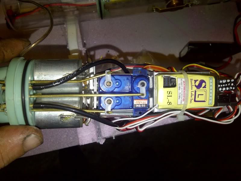
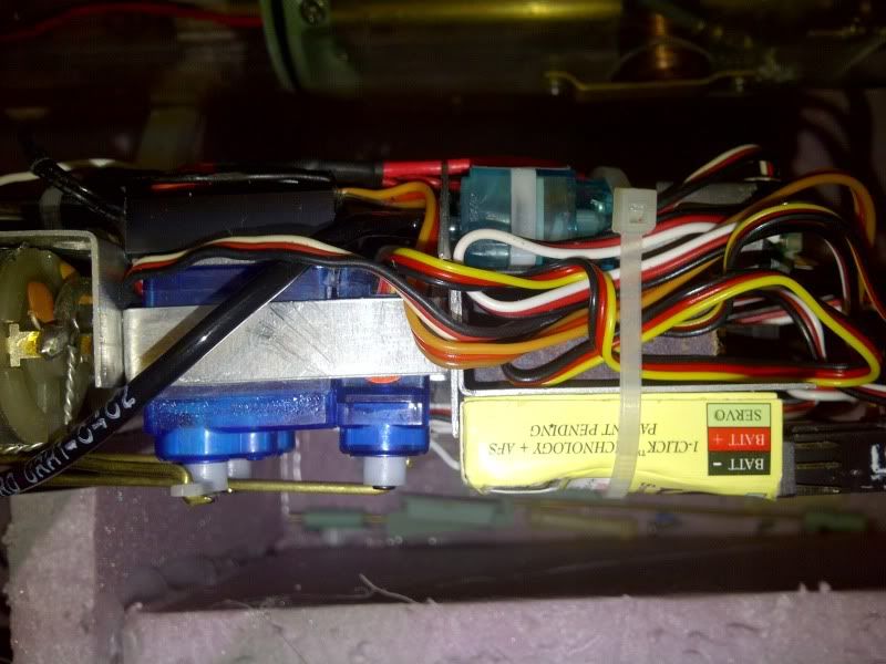
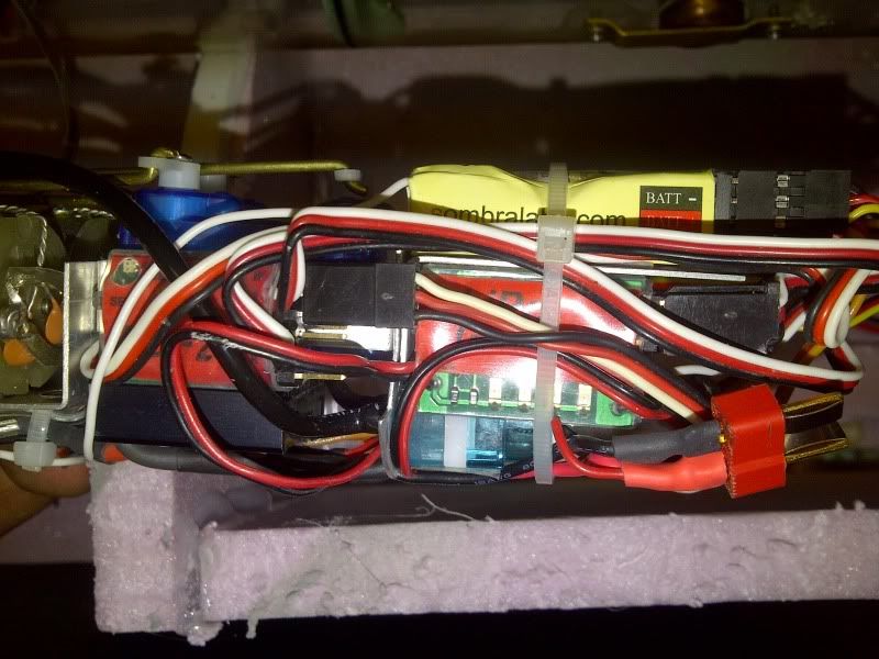
3) Where do you mount the lipo guard, the receiver and the ADF? I see that there is an aluminum shelf in front of the 3 servos. I was thinking the the ADF should go on top with double sided tape, the lipo guard on the bottom side of the shelf,and the receiver loosely pack below that.
The receiver goes atop the horizontal bracket on the forward face of the aluminum bulkhead. The ADF to one side of the servos, the Lipo-Guard to the other side. (I am using automotive double sided tape, works very well)
4) The long wiring I guess connects the battery from the forward compartment through the brass tubing to the two speed controller power leads using the Dean connectors. Is that correct?
I hard-wire the battery cables to the ESC (as well as the Lipo-guard and MPC power wires -- all of which are wired in parallel), but if you can squeeze it in, you can use the smaller sized Deans connector. (I have hardwired parallel JST connectors to the battery wire since my battery use JST, this works well as a quick release and is fairly small. I have a balance charger - iCharger 106B, a separate 350W power supply, balancing adapter board and a 6 wire power leads to charge up to six batteries at the same time (do this for all my helicopter lipo batteries; saves time)
5) Does the ADF control the rear planes using Channel 5 on the Wfly 6 channel transmitter? (My mistake, it is on channel 6)
I use channel-6, the nob to the left.
6) the way I have wired the parts is as follow:
ADF lead A is connected to the receiver channel 6 which is controlled by the dial
ADF lead B is connected to the Lipo Guard which is then connected to the receiver channel 4 which will operate the vent/blow servo
Yes.
ADF connector C is attached to the forward planes servo
No. To the receiver, channel-4 port. (My response to this answer is the C connector according to the ADF instruction is an output male connector. I don't see how connecting it to the receiver's output would work)
ADF connector D is attached to the vent/blow servo (need a lead extension as the vent/blow servo lead barely comes out of the lexan tube.
Yes and yes.
The Lipo Guard power leads is connected to the battery at the same connection point as the speed controller's power leads
In parallel, yes.
The rest of the transmitter/servo channels are:
Channel 1 - Rudder
Channel 2 – forward planes
Channel 3 – speed controller
Channel 4 – Vent/Blow
Channel 5 – not used (will be used for the LPB)
Channel 6 – Rear planes
That's the way I do it, Andrew.
DavidLeave a comment:
-
The SD has been shipped. In the meantime I am waiting on the LPB and looking for trim foam. I was able to find grey foam used for piping insulation, does not absorb water and comes in a split tube (to fit over pipes). It is approx 5/16" thick and since it curved and pliable, I think it will better conform to the hull. Any thoughts on this stuff, it fairly cheap (about $2 at Home Depot for a 6 foot length that is 4.75 inches wide).
AndrewLeave a comment:
-
OK, send it to me. I'll fix you up, Andrew.
DavidLeave a comment:
-
Hi David,
My soldering skills is limited to wires and that is average to marginal (don't have the right equipment or enough practice). I have never soldered anything like this before and especially something that is under pressure. A mistake could sink and lose the sub. I would prefer to send back the unit for repairs as I probably will break a spare part given the limited access and tight space. I know my limits and with so much money already invested, I rather let someone who is familiar with the SD and knows very well its assembly to repair it.
Thanks for your help
AndrewLast edited by Avera; 06-27-2012, 04:34 AM.Leave a comment:
-
Well, that did not work out either as the solder connection on the blow valve came apart as I tried to reinstall the valve in its slot. I was being very careful, but the little hoses are stiff and the hose configuration has a twist in it as it goes from the ballast tank to the blow valve. As I tried to manuever the value so that the little copper elbow coming off the valve could enter its slot, the copper assembly came apart.Last edited by Avera; 06-26-2012, 05:38 PM.Leave a comment:
-
No big deal, Andrew. Here's what you do:
1. undo the on-board bottle fastener, then apply pressure to the top of its charge fitting till you break the RTV bond between the top of the bottle and the Lexan cylinder
2. remove the bottle from the cylinder through the big hole in the bottom of the cylinder
3. make up the blow-valve plumbing to the on-board bottle nipple
4. reinstall the on-board bottle -- don't forget the RTV to seal its top against the cylinder and make up its retainer
5. make up the blow-valve to the after ballast bulkhead
I can do this in five-minutes. You? Longer.
DavidLeave a comment:



Leave a comment: