
Hi David,
I was looking at the photos of your VIIC sub SD and noticed that the induction manifold and fill manifold are one unit. The SD came with them as two separate units. I assum this is not a be deal, just requiring the gluing of two parts instead of one and perhaps allowing for better location of either one.
-
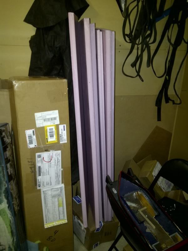
I got my foam at the local hardware/home improvement place (lowes, home depot...etc) I got a full sheet of 1/2 inch thick and a full sheet of 1 inch thick... I use the 1 inch for working/transport stands, and inside my other boats if needed... and cut carve shave the 1/2 to fit for the sub... pink exterior foam.. I beleive it's ment for under floors, and under siding
I don't have a truck, I have a 4dr econo family sedan... I asked a nice person in the home depot with a sharp blade to make each sheet 4 pieces for me...
I think it was $18 cnd with taxes
Leave a comment:
-
If you just press-fit the after most manifold in place, it will work, but a bit of water will get into the line -- no big whoop, it's a closed loop and none of it can get into the dry spaces. I glue mine on -- come on! ... how much work is it to slip two flexible hoses on and off their nipples?!! If you do, take care not to get any RTV into the lines!
You use the brass-tubes-on-one-side-a-single-tube-on-the-opposite-side LPB manifold only if you need to run the induction line well forward. If you do, it becomes an intermediate manifold that dumps discharge air into the ballast tank, but runs the induction hose forward to the specialized LPB manifold previously discussed.
You can make those flexible hoses a looser fit to the nipples by heating a 3/32" wire slightly and sticking it into the end of the hose. That permanently expands the hose a bit and reduces its hardness.
You people!
David
Leave a comment:
-
Hi David,
Is the stern manifold glue on or just pressed onto the brass tubes coming off the bulkhead?
In either case both lines run from the stern forward with one going up the sail (induction line) and the other going into the ballast tank (need to drill a hole).
Now do both of these lines attach to the manifold that has two brass tubes on one side, a single tube on the opposite side and a hole on the bottom where it attaches to the hull?
Now here is the big question for me and probably relates to the stern manifold, do I have to pull off the two hoses from the stern every time I want to open up the stern dry space? If the stern manifold is pressed on, then the process is simple; just pop off the manifold and remove the stern bulkhead from the Lexan tube. The alternative is a little bit harder as those tube are on tight using a blow dryer to soften the hosing to get it on/off.
AndrewLeave a comment:
-
If you have a situation (the 1/144 SEAWOLF is a prim example) where the sail is way forward on the hull and you want to put the sail induction line at the extreme front end of the SD, you use this manifold. It transitions the vertically placed hose that runs up into the sail to a horizontal hose that runs into the middle manifold where it is passed on to the manifold on the outer face of the motor bulkhead. Most people won't need this LPB manifold.
DavidLeave a comment:
-
-
Hi David,
Going back to the LPB parts or manifolds, in your video (thanks for making it), I see the SNORT system in the sub but only two of the manifolds being used. The stern bulkhead one and the one that sucks in the air. I don't see the one that pumps the air into the tube. Are you using it?
video link: http://www.youtube.com/watch?v=r27INRGIYhE
AndrewLeave a comment:
-
On a side note regarding the trim foam, any thought on the grey plumbing foam used to insulate pipes? The form comes in a split tube 6 feet long by 4.5 inches wide and about 3/8 inch thick. It appears closed cell (nearly as dense as neoprene but lighter) and does not retain water. Giving its curved shape, it should easily conform to the hull. My LHS does not carry any of the pink foam, nor does the local craft store.
AndrewLeave a comment:
-
Hi David,
In the forward dry space, there is only the battery (I am not using a switch), so I am not sure why there is a strain relief in there.Leave a comment:
-
That one with the 'partially drilled holes' is a strain-relief block that goes into the forward dry space and is CA'ed to the inboard face of the forward bulkhead (removable cap).
Let's have a picture of the 'mystery' LPB manifold.
DavidLeave a comment:
-
Avera, that pdf for the Seaview answers a lot of questions- glad you found it!
Okay, the extra port in the back is just that- leave it alone...
And also from pdf and Reckless you rig up your own pin where and how you want. But can't be done until dogbones are in place. I'm putting the cart before the horse.
I suspect placement of the second manifold and top entrance hole from LPB the same way- wait until everything else in place. It would be nice to have the extra SAS stuff by then, to decide on a good compromise using both GAS and SAS for sail placement of tube going down to 2nd manifold.
Still a puzzle exactly how the right angle manifold and that block with partially drilled holes in it does or goes.Leave a comment:
-
no saddles or bulkheads.. the SD barely squeezes in... basically setup the driveshafts, line up the SD with dogbones ... this is your SD's new home...
then pick a spot for the indexing pin in the bottom of the hull... in a spot that coresponds with a spot you can safely drill a hole (or 4) in the SD ... aka bottom of the ballast tank..
took me 4 holes from where I initially indexed my SD ... then velco strips over top to tie it down inplace.Leave a comment:
-
On question one I'm sure on what the rear and middle manifolds are and do. I just don't know where to place the 2nd one wrt a reference on the SD tube, so that BOTH Gas and SAS can both be used. There is no pre-drilled hole to fill tank from above.
The first "right angle" manifold I have seen in a Gazette picture placed way up front. Here, it can't be used to go up to the float tube or induction tube, since it's right below the VIIC deck- no room. This is what I refer to in question #2...where does it go and what does it do? The right angle manifold. This ties in with placement of the SAS safety valve- a small brass can that because of space will have to sit outside of the VIIC SD...either in front or behind (if it fits with all the rods and shafts).
Now if the safety canister goes in front, that first right angle manifold might come in very handy, but I don't have the logic in my mind straightened out as to whether it sticks on up front or next to the middle manifold or ...? And orientation. A wild guess is a line goes from the middle manifold towards the front, then connects to safety canister and T connection, then runs back to middle of SD where the first right angle manifold (is glued) directs it up right under the sail to the float valve.
The block you refer to I believe may have something to do with SAS float install, but whatever it is, that was not my question. It is a good question though...?
In question 5, if the connection is not used in this sub but in others, why doesn't Caswell just not install the seal and glue hole closed? Or at least pull the rod out and jam some RTV in the seal hole. One less seal in a bulkhead to worry about.
Thanks for the link. I've already pulled down a lot of pdfs from the site, but not that one.
I think the one BIG comprehensive question I have is: how do I put together with careful enough alignment/placement to allow for both Gas and future SAS? Pics optional, but nice.
Sorry if I sound cranky, the Colorado fires have a lot of smoke in the air and everyone is like this.Leave a comment:
-
Hi H20haze,
1) I am still new to all of this and in the learning stage. The three "manifolds" I believe are for the SNORT system (an optional purchased air pump to drain the ballast of water once the periscope breaks surface (assuming the intake tube is there). Those manifolds redirect the intake to the pump then back out to the ballast tank. In the ballast tank should be a a small copper tank that is charged with air and used as either a primary of backup system to empty the ballast tank of water. I still am not sure of the exact placement and I will soon be corrected by David, but I think the one with the two parallel tubes goes on the stern bulkhead to direct the air tubes forward. The next manifold has two tubes on one side, one tube opposite and an hole on the bottom. This should get placed over a hole on top of the lexan tube over the ballast portion to allow air from the pump to fill the ballast. The other in/out brass tube is for the air intake and just connects the tubing to the third manifold. The third manifold consisting of a single 90 degree tube is the air intake which directs the intake tube through the periscope.
2) Not sure what you are referring to, bu I also got a small angular block with three dimples on each side. I don't know what that is for.
3) I cut the upper limper holes, all the holes around the forward planes, most of the hole around the bow (series of 12 round holes and three oval on each side above the torpedo doors), Five oval holes on each of the stern tubes, the stern torpedo tube is open per the fitting kit, and I have three 1/4" holes on the bottom where the rectangular plates are mid-ship. I couldn't cut them in the rectangular shape.
4) Once I get back my SD (went in for repairs), I will position the it figure out where the SNORT tubes and manifolds should go, make a mount for the tube including the index pin and strap. This is all depended on seeing where the SD lies when I add the dog-bone collars.
5) The fourth connecting rod serves no purpose for this sub. I guess the rear bulkhead was designed for several subs and easier to make them one way to be adaptable or perhaps for use of a rear torpedo tube system. That is my guess.
There is a really good PDF on this site regarding the Seaview which describes very well the SD and all of its components. Took me a while to find it, but very useful. http://support.caswellplating.com/in...r-instructions
David or anyone else, please correct me if I am wrong in the above.
AndrewLast edited by Avera; 07-03-2012, 09:05 PM.Leave a comment:

Leave a comment: