Thanks Tom.
At first I though the styrene tube would be tricky to handle attached to the sd but with all the handling this past week its held its own. The nights are getting a bit cooler here so instead of priming the lower hull I have been busy on the servo, push rod and electrics in tje motor dry space. I'll post up some pictures tonight when I get home from work. The only thing left to do from the electroncs side is set up the switch and battery connections and wire up the esc when it arrives. Last night I managed to get the first coat of primer on and did a pressure test on the sd for leaks.... of which there were none :) If it all goes to plan I reckon I'll be doing the first open water test in 3 w/ends from now....... To be honest my motivation is suffering a bit. Since October last year I've been at it hammer n tongs on my models with no decernable break between projects. But I stiil see the Gato in the water on a full patrol by June/July then I'll rest!!! LOL...
-
Alec,
I love the use of styrene for the Snort system! Should make it lighter too!
Peace,
tomLeave a comment:
-
Another update...
I must admit that this week has been as much rewarding as it has been frustrating!!! However perseverance and stepping back has seen me through to another completed stage. As of this morning I have finished all the preliminary non electrics on the sub driver such as the ballast LPB plumbing, the aft bow plane control set up and push rod set up. As well as getting the top hull to mate with the lowerer hull with the wtc installed.
To cap off the week...
1/ hulls mate off again.
2/ SD indexing pin installed
3/ No more binding of the bow plane mechanism
4/ setting the LPB plumbing from the intake to the ballast tank.
I had to replace the bell crank for the torque bar due to the resin supplied one breaking... I noticed during cleaning and prep it had a large air bubble pocket in it. So I filled the offending cavity with ca and baking soda...
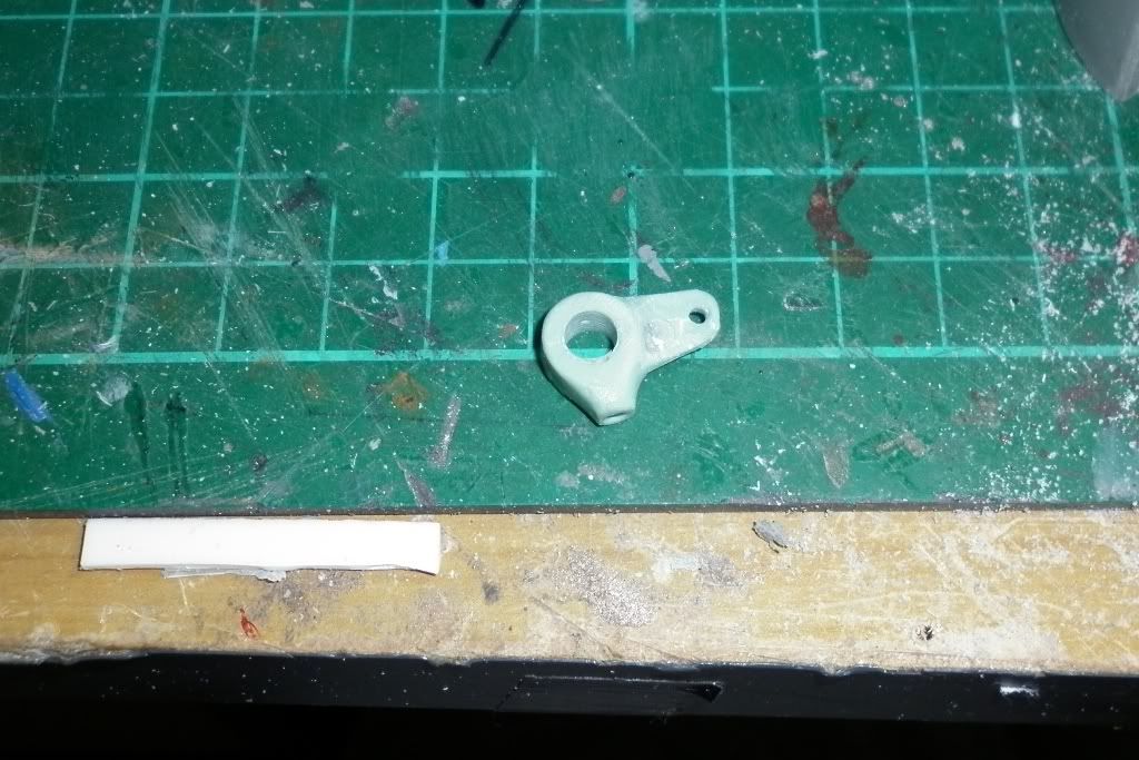
Sadly it still failed during fitting and testing. I believe that the binding of the bow planes gears and the air bubble proved to much for the piece...
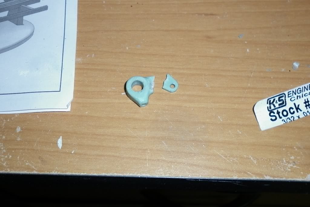
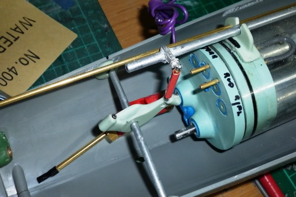
with a burst of aussie slang and expletives I sat back to ponder a replacement... Usually when this sort of thing happens I back off and then attack the problem fresh. What this did was lead me to a piece from the extras out of the Seaview kit which was an extra rear plane bell crank. With measuring, filing and careful drilling I was able to get it to fit the torque bar. Granted I didn't have much metal to use a grub screw to lock it in place but thats where ca and baking powder come to play. Once I filled away most of the white cast metal on the ball joint the magnets stuck to it like baby **** to a blanket
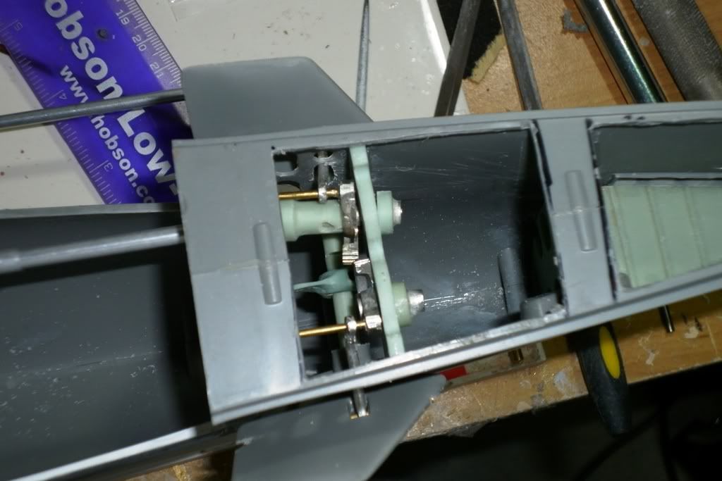
That done I spent the next several hours on the bow planes gear mechanism. The dog bone shaft was very loose and sloppy causing the gear to sit a kilter to the opposing one. again some scrounging and thought process gave me the solution of making a shim from one of the alternating rear bow plane control shaft hull mounts... One it was in place the gears mated beautifully. There was still a little binding but after some cleanup and tweaking the mechanism push rods it all moves effortlessly
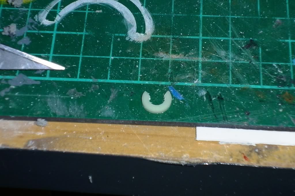
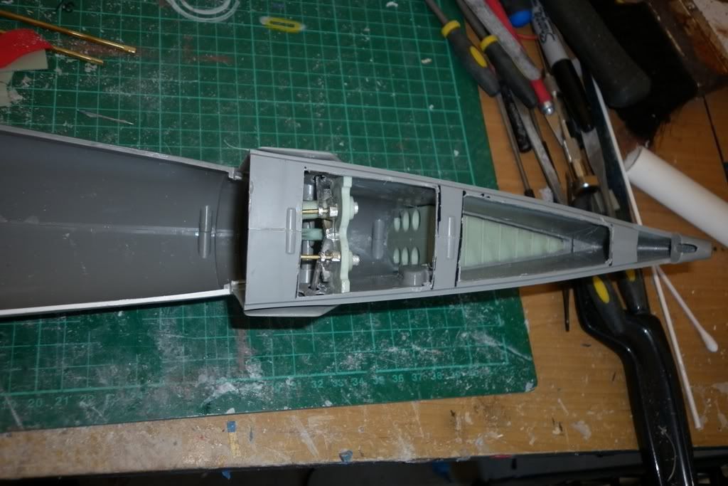
I got the idea for the LPB plumbing from Trouts build thread. I know on my Seaview I used the black tubing supplied and held it down with electricians tape but I wanted a cleaner more mechanical look so I took two evergreen tubes blocked up to match the resin piece supplied and then glued them in place with clear rtv silicone. The resin piece supplied it fixed to the sd and I drilled a matching hole to take s small piece of the tubing going from the resin block int the ballast area. I then used two pieces of brass tube at the aft end of the styrene tubes to attach the lpb tubing from the motor bulk head.
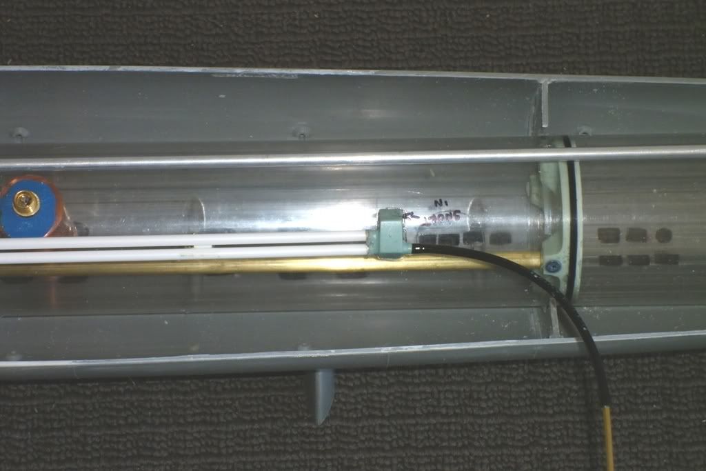
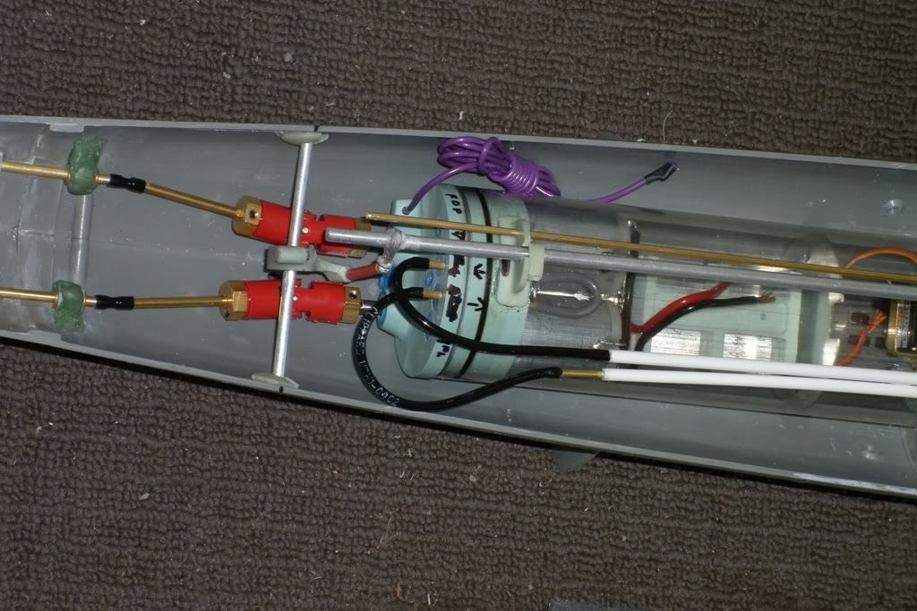
On the inlet side of the resin block I added a length of tube along with some brass tube that slids into the periscope/inlet I made on the conning tower
Onother modification I did was on the forward end of the torque bar to make it whilst attatched the wtc. I replaced the origional torque bar with one that fitted the resin supports on the wtc better. Then I cut off the front of the origionl piece I had with the dog bone head attached and slid it inside the larger tube. I then drilled a small hole hole through both of them and held them in place with a spring clip so when it comes time to take out the sub driver I take out the clip and slid the dog bone head back.
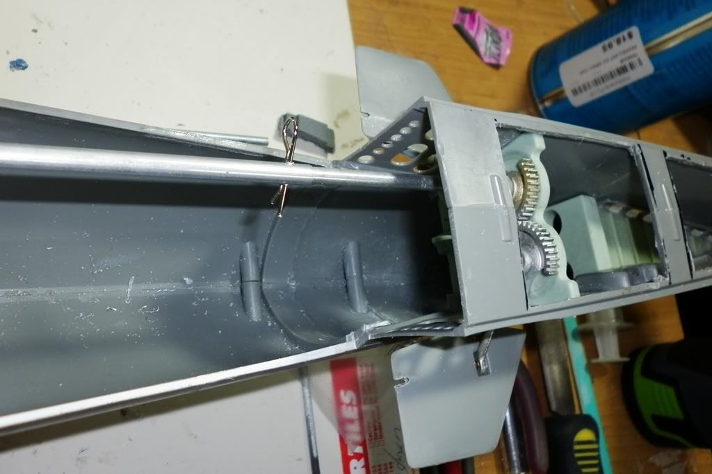
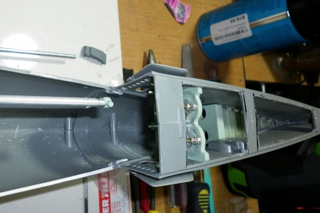
Now I can get back to finishing off the lower hull with filling and priming whilst waiting for the esc to arrive.Leave a comment:
-
Grind away. and to perfectly identify where the torque tube is making contact with above structures:
Brush some dark colored artist oil (slow-dry linseed oil based tube color) to the upper portions of the torque tube. push the upper hull down on the lower hull as far as you can, then remove. The oil that stained the upper hull structure indicates where there is contact between those structures and torque tube. Grind. Repeat the process till there is no paint transfer between torque tube and upper hull structures.
DavidLeave a comment:
-
Thanks David. That is good & means one less piece of electrics to worry about.
Last night I fitted the dive plane torque bar mounts to the sd but I am now finding that the bulkheads on the superstructure seem to deep to et it sitting down properly on the lower hull. I reshaped the lower bulkheads so the sd sits nice n low, just under 3/8th of an inch from the inside keel. Any lower and I'd be grinding away at the locator pin & blocks in the hull halves. I set the bar mounts so that it is in line with respective pushrod seal otherwise they snag on the inside side curve of the top piece. I have marked out where to grind out on the top bulkheads but my concern is that by reducing them I am at risk of loosing their strength at maintaining the top pieces profile. Did I miss something in the cabal reports that explains it & will show us all that I am a right royal richard cranium...Leave a comment:
-
The motors are rated for 12-volt. And no harm running them at 7-volts or so. But, if you have already put a voltage limiting resistor in line with the power leads to the LPB (it's motor rated for 6-volt operation), take it out of the circuit or your blower will take forever to push the water out.
Good looking work so far, Alec.
DavidLeave a comment:
-
Yes David I did mean mill-put & not the other green stuff. It's what I have been calling mill-put for decades from my war gaming days... I suppose I should say what I mean & mean what I say... I had intended to use the fittings kit part for the planes. I was just being lazy for the sake of it. So now that I have been 'told' the correct parts will be added. Thanks for clearing up the esc for me too. I will place an order this week for one. Now a question on batteries. I know an 11.1v battery is recommended but can I use a 7.2v pack rated at 3600mh? I have a brand new battery pack and don't want it wasted as it is too big to fit into the seaview.Leave a comment:
-
Alec,
Good, sound kit-assembly going on here (you trophy-hound, you!). And no big whoop if you scratch your finish during work-up and sea-trials -- you obviously have the chops to put things right once you decide to make the thing contest worthy. Good stuff so far.
Now, as to that bow plane retract mechanism hanging-up-at-the-half-way point business: I see in the one photo that you're still using the kit provided bow plane operating shafts. ****-can those and use the ones I provided in the GATO fittings package -- their bow plane wrist-pins are canted a bit, to better make the planes nest into the wells on the sides of the superstructure when retracted. That same slight angular displacement from the expected 90-degrees also eliminates the transverse load otherwise experienced by the retract struts -- which currently accounts for why the mechanism is dragging on you.
Examine the kit provided bow plane operating shaft pieces and mine: they're not the same. You think I did those just for show? Put 'em in!
I hope you meant milli-put (a two-part isothermic curing filler/foundation) and not 'green stuff' (a very low quality air-dry touch-up putty)?!
Get the MTroniks Marine-15.
You need five servos in there: ballast sub-system (came with your SD), rudder, bow plane, bow plane retract, and stern plane.
Good looking stuff, Alec.
FINISH IT!
DavidLast edited by He Who Shall Not Be Named; 05-13-2012, 09:23 AM.Leave a comment:
-
Yeah I tell myself that all the time... It's your model Alec so do it how you want. The trouble is I never let myself get taken away with "artistic license" as I usually find myself caught up in some sort of research and accessorizing them. which in the end gets me a good blend anyway. Three bronze, a silver and a gold in the last couple of modeling expos means I must be doing something right???? But enough blowing smoke up my own butt. On with my Gato story...
I will be honest and say that with out the DVD's I am enjoying the challenge of this project so far. Since Thursday I have now done the base coat colours and preliminary drybrushing of the top hull section. I know David recommends doing that after it has been trimmed and tested but the little modeling devil in me is a hard sucker to resist...
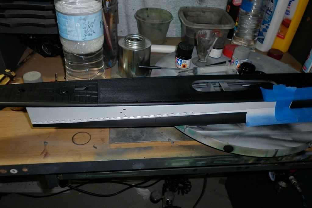
and masked up for the medium grey section...
The aft section with the medium to dark grey drybrush.
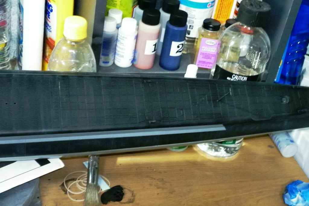
When it was all dry I put it on the bottom half to see how the split would look(in theory)...I even went geekier and sat the conning tower and deck gun in place and damn it looked good, even with no weathering enhancements yet. No picture though, it was more a self gratifying thing before bed.
Over the week-end I have added the bow plane mechanism and the basics of the torpedo tube fittings from the kit. even though I will most likely never add the working torpedoes anyway.
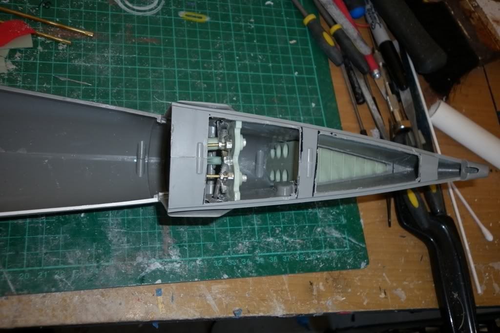
As for the torque bar to operate the mechanism I used one of the dog bone heads from my seaview fittings kit that had broken due to a poorly made shaft set up. I simply drilled out and dressed the head to accommodate the aluminium tube. I'm trying to keep what I can simple... So we'll see how good it works. Fitting the bow plane gear was a difficult task just fiddly getting it to sit right and operate the planes. There is some binding at the halfway point but I don't think its enough to bother the servo and torque bar.
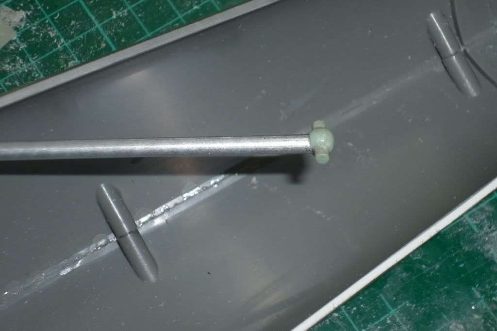
The only out of scale thing I did extra was to extend the hole where the planes retract arm operates through to get them to work properly. Other things tested and fitted were the rear planes and rudder. All now have been test fitted with push rods to match and awaiting the assembly of the subdriver servos and I decided to extend the inner bearing tube for the rudder so the bell crank had some support and it also helps align the rudder shaft as well.
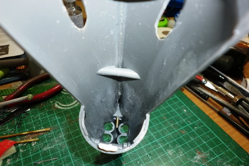
Sorry for not using the blocks in the fittings kit David but I was after a smaller looking set up in the hull.
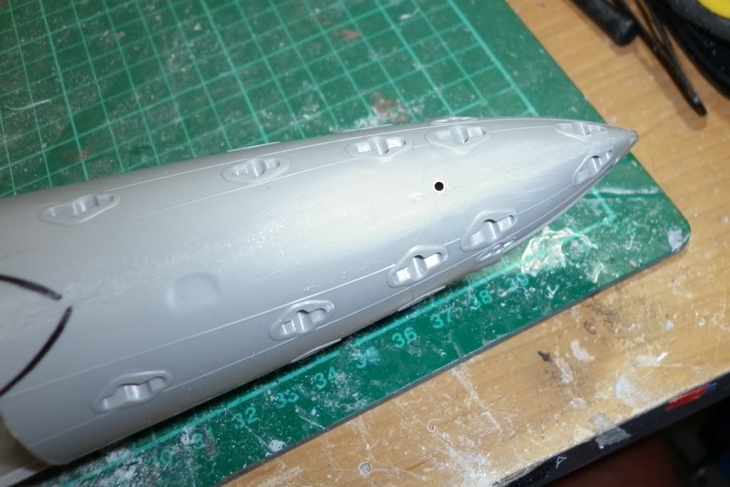
Saturday night also saw the use of the templates I bought from Caswells and then grinding out the flood vents in the lower hull.
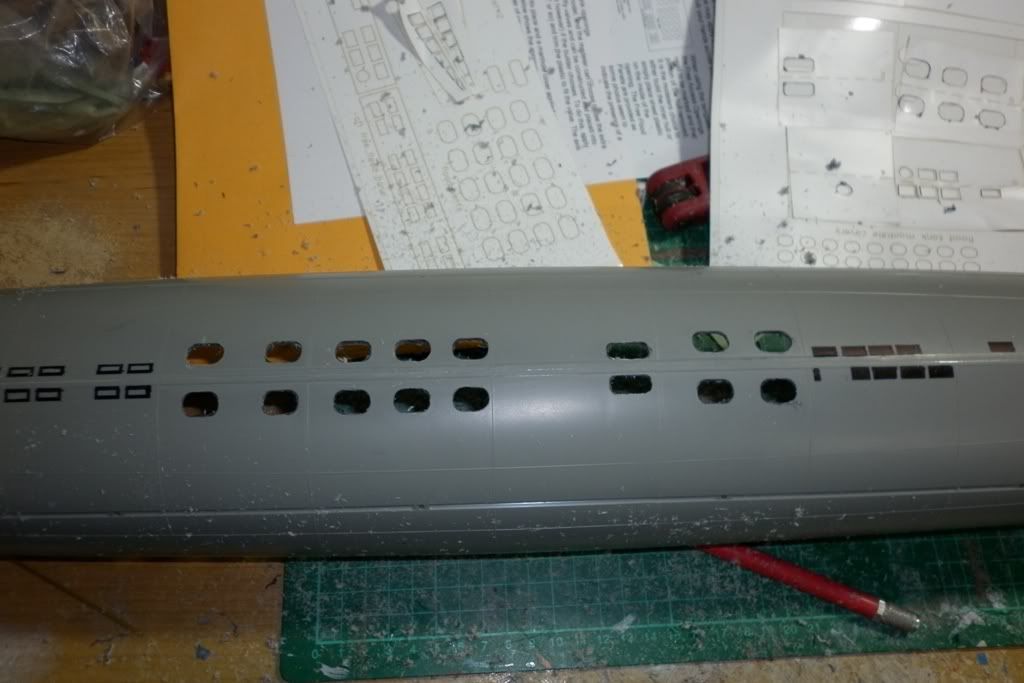
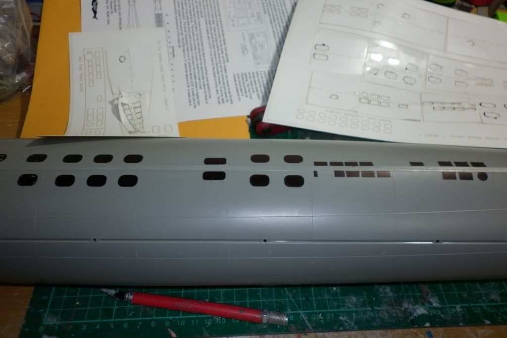
During test fittings and measurements I also noticed that the sd is shorter in length than what it says on Caswells? Which confirms what I read on one of the threads somewhere. I do like the current configuration, as the ballast tank bulk heads fall right on top of the two hull bulk heads. Which by my workings has the center of the ballast tank in the center of the boat. David you are a clever man. Today saw me fitting the running gear though I had to figure out some minor modifications to what David mentions in the cabal reports. My local rc shop doesn't carry the Dumas style couplers and fittings. They carry a universal type of set up which kind of threw me when I added the prop shafts and fittings today. I lined everything up with several dry fits holding the strut bearing in place with tape as I got the long shaft resin bearing tube in position. At first I thought I screwed up the lay of the prop gear and shafts but they followed the line of the kit parts which I had used as my guide. The problem was the universals I have they are ok with a small off-set. How ever what I have after installing the running gear was way to much off-set and trying to run them as such would have added all sorts of loads n stresses to the prop shafts etc. My solution was pretty basic and one that I hope works. I used some tube to act as a mini flexible uni-joint leading from the oilite bearing to the universal mounts on the motor drive shafts. The other thing I had to redo was mount the oilite bearing blocks a bit differently. Ideally it should sit up to the resin bearing tube but I had to sit mine away a bit so I mounted it in a foundation of green stuff.
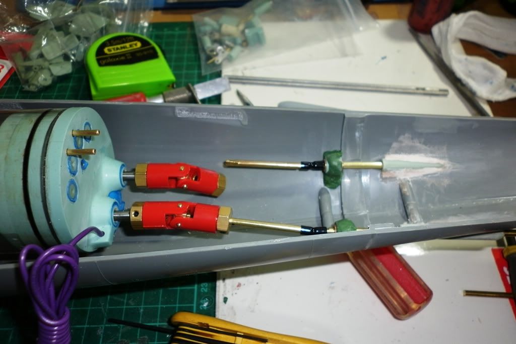
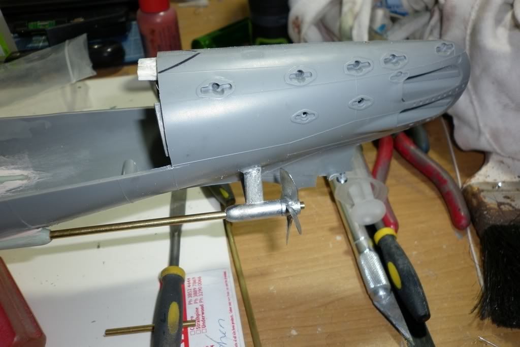
I will leave the drive shafts in place till the green stuff fully cures that way all the alignments shouldn't change. In the pictures above you may notice that the shafts are brass not s/steel as supplied in the kit. due to the modifications I had to make new ones. I still kept the diameter the same all I di was use brass rod and cut it longer and then filed a flat on the ends bar where the prop will be glued. That way they will sit better with the grub screws and it also made sliding them into the tube easier. Now I just hope that these mods don't apply to much of the wrong stresses to the running gear?? BTW the prop is just for show at this point. One important question I need to ask is which esc do I need to run the motors?? I found a mob down here in Oz that sells the Mtroniks ones and apart from one more servo, as the instruction sheet says I only needed three, which I dutifully followed but it bugged me all day at work on Friday that I missed something. Sure enough I should have gotten four.Last edited by alad61; 05-13-2012, 08:38 AM.Leave a comment:
-
This week has seen that most of my bench time is on my seaview sd and related 'issues'. However I have slipped in some time on the gato, most of which has been sorting through the fittinge kit and sd tha turned up. Woohoo... With what I have done so far most of the fittings will just drop straight in once I give them a was n scrub. Last night I did the base colours and drybrushing to the top section. Like the conning tower this will be filled out of the way so I can deal with the bottom section. I'm not sure what I was thinking, actally I wasn't, but in my list of parts from Caswells but I didn't add or order the DVD!!!! Talk about a fraudian slip on challenging oneself... But with all the posts,threads & knowledgable people on here as well as Davids cabal reports I cautiously confident enough to get it right. Btw David I love the bow plane mechanism too. Yesterday was a shopping day at the rc shop to collect the extras needed. So all thats left is to get an esc. Though working on the sd proper is a ways off yet so no rush just yet.Leave a comment:
-
You think they would have mention about the breather in the booklet and so make it an optional piece... So off it goes then. I do agree with you about the flag poles but I can't bring myself to take them off and as for the hydrophone I am considering using a small piece of brass rod as the thing is pretty flimsy, more so than the flag poles. I may even do the same for said flag poles and the antenna foundation? I like Toms idea with the magnets on the rail foundations but a klutz like me would still end up doing damage to them with handling and storage. When the primer was dry on the top hull section I sat the conning tower & deck gun in place and it looks mighty fine without the rails to clutter it up more, not to mention they'd be more crap on the decks to catch weed, reeds and stuff out on patrol. Mmm so why, I ask myself, am I leaving the flag poles in place then??? Short answer I like the look.Leave a comment:
-
The 'breather' was part of a ventallation system added to the mueum boat from which the Revell guys got their documentation -- not a fixture on active, commissioned boats. Drop it.
And you'll break off those flag-staffs in no time, I can assure you of that! Make the deck mounted passive sonar head removable -- and make its vertical element from metal, the base of which slides into a metal insert placed into the deck.
Give us an after-action report on that SEAVIEW run, Alec.
Good stuff! You kit-assembling machine, you!
DavidLeave a comment:
-
Another week worth of work seemed fairly successful. I reckon I am getting as close to the end of the grunt work on the basic hull now as I can with out the sd and fittings kit. I deviated a bit from Davids advice on what was on deck for mission runs in that I added the forward & rear flag poles, aerial foundation Along with the hydrophone and breather. Time will tell with handleing if these additions were a good idea but I like the look it gives, simple as that. So with those added all that left for the superstructure section is priming and painting. I'm very happy with the way the two hull sections sit and I found I only needed to add fillets to the top section which help a treat in getting the lower hull to conform with the top so I lucked out there as to not really needing to add filler to bring it all together. I have also decided that I will paint weather up the top section mostly due to the size of the beast and the limited space I have in my work space.
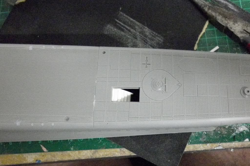
Ok, some picks of whats been done. The first are cleaning and filling the seams and rail mounts in the deck and forward superstructure. One way that I use to fill and fix some troublesome seams is sanding the area then working the styrene dust into the area and adding the liquid glue to melt and weld it together...
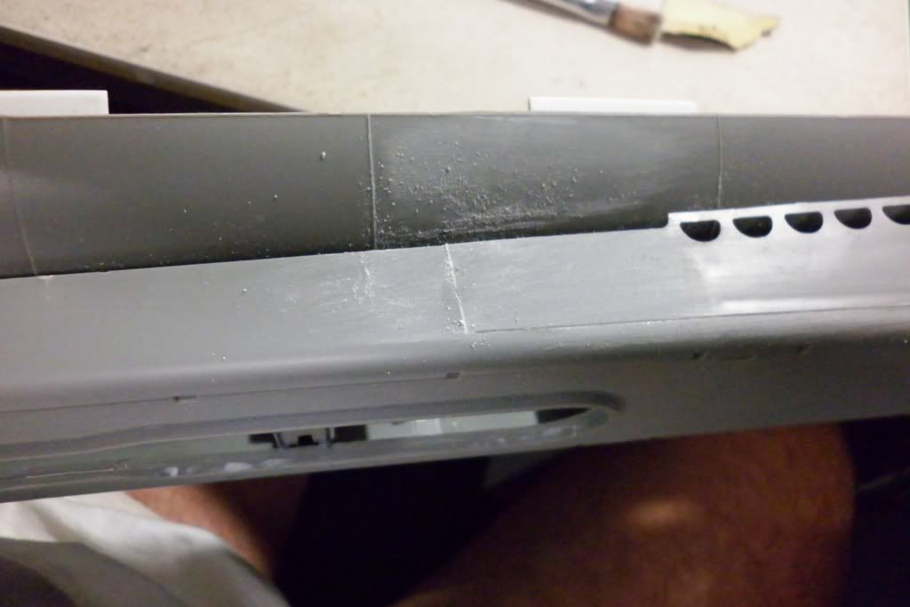
Then adding the bog and it's here I took Davids lead and used masking tape to keep the filler from going places I didn't want...
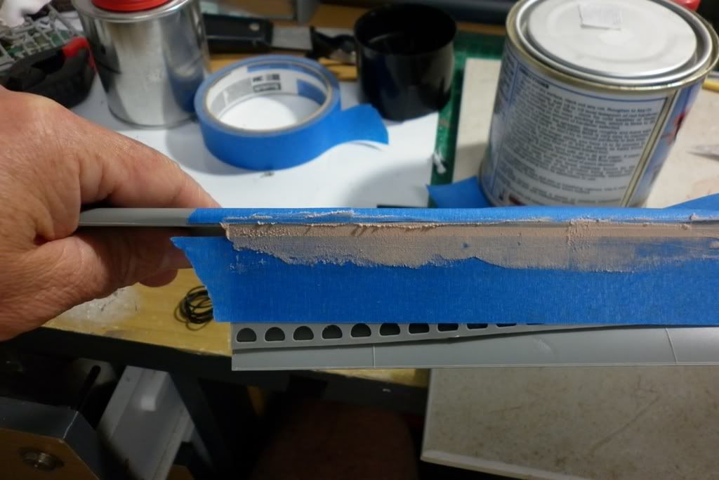
The first run of filer in the rail support holes and then another pass of a a finner filler to take up the areas that had some shrinkage etc...
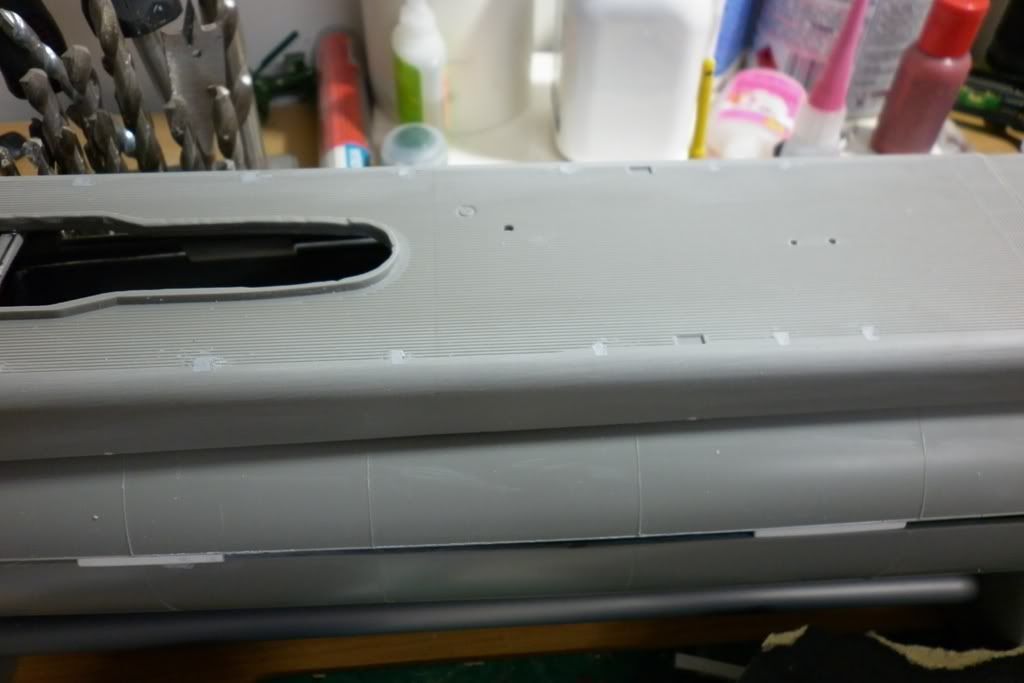
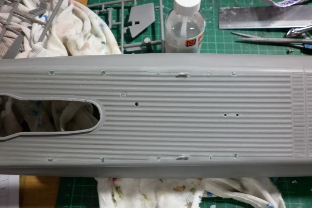
Somehow I had lost the forward gangway ladder so I knocked up a new one. So much for checking and bagging loose pieces :(
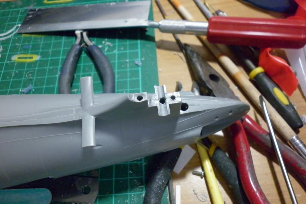
The next couple of nights I finished off the skeg and prop shaft mounts and drilled and preppaired the rudder and forward dive planes.
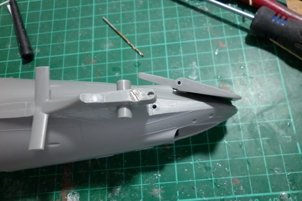
I need to fix the shaft hole in the skeg with some bog as I went a bit askew with the drill...Scuba Diving
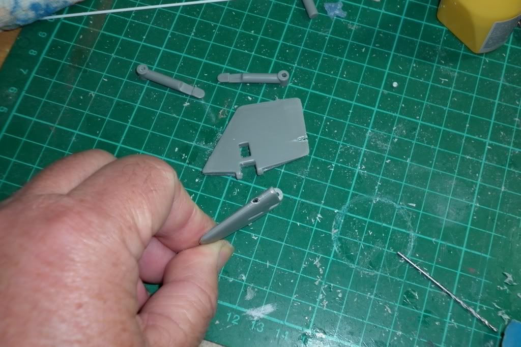
Tomorrow it's off the hobby store for more brass rod and wire and then I'll start painting up the top superstructure section... As for today I'm off to run the Seaview with the new motors. :biggrin:Leave a comment:
-
Good work. And a 1/32" kurf is not enough lost material to worry about. Well done, sir!
DavidLeave a comment:
Leave a comment: