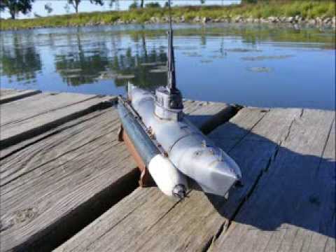
Bibers scale 1:35

Collapse
X
 
  • Time
  • Show
Clear All
new posts
  • MFR1964
    Detail Nut of the First Order

    • Sep 2010
    • 1635

    #1

    Bibers scale 1:35

    As promised i did some digging in the archives, buckle up,here we go

    I must mention all the work on the Bibers is done by my mentor, the only thing i did was bringing them back to live.

    Click image for larger version

Name:	20220126_192658.jpg
Views:	417
Size:	54.7 KB
ID:	178844
    These are the mold derived from the Verlinden kit, he used them to make the glassfiber hulls

    Click image for larger version

Name:	20220121_193011.jpg
Views:	296
Size:	55.3 KB
ID:	178845

    Click image for larger version

Name:	20220121_193031.jpg
Views:	287
Size:	54.4 KB
ID:	178846
    Those are the Bibers after i did some work bringing them back to live.

    Click image for larger version

Name:	P7280497.jpg
Views:	279
Size:	43.9 KB
ID:	178847
    Just before i started opening them up

    Click image for larger version

Name:	P7280498.jpg
Views:	273
Size:	45.7 KB
ID:	178848

    Click image for larger version

Name:	P7280499.jpg
Views:	274
Size:	48.6 KB
ID:	178849

    You can split them open by removing some small screws, the made a metal flange on both halves, used RTV to make a watertight connection
    As you can see he placed some small gears to get some more torque from the motor, and used as a transitions to the height of the propulsion shaft, i suspect it is rated 3:1

    Click image for larger version

Name:	P7280500.jpg
Views:	273
Size:	46.7 KB
ID:	178850

    He made some cradles to hold both servo's, one for the rudder and one for the divingplanes.

    Click image for larger version

Name:	P7280502.jpg
Views:	271
Size:	44.5 KB
ID:	178851

    Those servo's where burned out, you can see the bulge at the bottom, the reason it happens is, to much voltage at the servo's, he used a batterypack rated 6V, those servo's are rated 4,8 V, i changed the packs to 4,8 V on both bibers, luckely the size of the servo's are allmost the same which i had in stock.

    Click image for larger version

Name:	P7280503.jpg
Views:	276
Size:	45.8 KB
ID:	178852

    To lubricate the shaft he placed two nipples, by removing them both you can fill it up with some light oil,usually this is done once a year during maintenance.

    Click image for larger version

Name:	P7280504.jpg
Views:	276
Size:	47.2 KB
ID:	178853

    View on the rearpart with both the rudder and divingplanes.

    Click image for larger version

Name:	P7280505.jpg
Views:	276
Size:	49.5 KB
ID:	178854

    The Biber disassembled, as a ESC he used a old servo print, replaced them both by modern ESC's to get more control on the speed, he used a 6 channel receiver, to control both Bibers i can use channel1-3 for one biber and channel 5-6 for the other.

    Click image for larger version

Name:	P7290508.jpg
Views:	276
Size:	49.5 KB
ID:	178855

    Replaced both servo's which i had in stock, they are clamped together with some small screws.

    Click image for larger version

Name:	P7290512.jpg
Views:	273
Size:	51.3 KB
ID:	178856

    Inside both torpedo's are the batteries, for long storage you can unplug them, the same connection is used for charging, switching on the Bibers is done by a magnetic switch which is hidden in one of the torpedo's.
    You can drive them for about 1 hr, more than enough time, they are dynamic divers and work surpricely well under water.


    Manfred.


    I went underground
  • Schmitty1944
    Lieutenant Commander

    • Mar 2021
    • 147

    #2
    Amazing. Thank you for showing and explaining the details. The radial split is a pretty clever approach. There is a fantastic amount of detail in those models. especially at such a small size.

    Unless there is something I don't see there is no gear reduction. All of the red gears have the same number of teeth. It is a very clever way to get the shaft at the bottom of the motor though. I did find your youtube videos "Reviving the Bibers, part 1 and 2" it looks like they have plenty of power and speed.

    I also found another youtube video of a 1/35th biber that is RC based on the Italeri kit. Not many details are given. It has a working ballast tank. It appears to use the torpedos propellers for propulsion and steering and maybe does not have moving controls? Included is a link to the video, note this is not mine and I don't know who the builder is but it may be from Canada?

    How do the seals work for the servo outputs in your Bibers (and Seehund)? You mentioned O-rings. Where are they located?

    Many thanks
    Jason.


    Comment

    • MFR1964
      Detail Nut of the First Order

      • Sep 2010
      • 1635

      #3
      Jason,

      You're right about the gears, i've checked it out on the pictures, only done to get it to the height of the shaft.
      As for the O rings, they are only used at the divingplanes, the rudder is sealed off by grease, he used injectionneedles with a tight fitted rod and a grease chamber, pretty much the same layout on the seehund.

      Manfred.
      I went underground

      Comment

      • Schmitty1944
        Lieutenant Commander

        • Mar 2021
        • 147

        #4
        Here are a few photos of the 2nd Biber I built based on a "toy" submarine. This one is completely working with a functional ballast tank. I just need to finish the details and paint and I was going to make more scale looking propellers for the torpedos.

        Click image for larger version  Name:	thumb_58782.jpg Views:	0 Size:	7.0 KB ID:	178960Click image for larger version  Name:	thumb_58783.jpg Views:	0 Size:	6.7 KB ID:	178961Click image for larger version  Name:	thumb_58784.jpg Views:	0 Size:	6.6 KB ID:	178962The ballast tank exposed on the bottom is obviously not very scale but it does work well. You can see the toy it is based on in the background and the controller on the left is my own modified version of the round blue controller that came with the toy with the buttons arranged to make more sense for the Biber.

        Jason​
        Attached Files
        Last edited by Schmitty1944; 03-21-2024, 01:30 PM.

        Comment

        • MFR1964
          Detail Nut of the First Order

          • Sep 2010
          • 1635

          #5
          The batteries inside the Bibers went dead, not surpricely after all those years, in the past i allready gave them a update with new ESC's and new servo's, this time i want to change them from 6V to 4,8 V this way i can eliminating the lonely battery inside the Biber, when done i don't have to open them all the way to replace batteries in the future.

          Click image for larger version

Name:	20260616_215101.jpg
Views:	78
Size:	50.6 KB
ID:	196214

          This was the lonely cell inside the Biber, my mentor made a kind of cup from copper penetratiing the keel, which offcourse is not scale but functional.

          Click image for larger version

Name:	20260616_170120.jpg
Views:	98
Size:	48.8 KB
ID:	196213

          Ripped the first Biber apart, allready closed the keel with some CA and bakingpowder, forgot to make a picture when i cutted her open at the keel, i'll sort that out when i start modifing the second Biber.

          Click image for larger version

Name:	20260616_170138.jpg
Views:	77
Size:	49.8 KB
ID:	196215

          Second layer of putty, i'll probably will need a third one before i can sand the keel into shape.

          Click image for larger version

Name:	20260616_215311.jpg
Views:	78
Size:	53.6 KB
ID:	196216

          The inside is closed with some evergreen plate 1mm, covered it up with 2K epoxy glue, that keel is a weak point due to the hole i cutted inside the keel.

          Click image for larger version

Name:	20260616_215339.jpg
Views:	79
Size:	51.2 KB
ID:	196217

          For those who want to know what's inside, a 5 channel receiver, a micro ESC, a small E motor located in the rearpart and two micro servo's for rudder and dive-planes, those Bibers are dynamic runners, so no ballasttank.

          Click image for larger version

Name:	20260617_220959.jpg
Views:	77
Size:	50.7 KB
ID:	196218

          New layout of the Biber, batteries inside the torpedo's and some foam to keep everythng at it's place, this side of the Biber only contains the batteries and connectors for the batteries, the other side has also a reedswitch to turn it on or off when placed on it's stand.

          Manfred.
          I went underground

          Comment

          • MFR1964
            Detail Nut of the First Order

            • Sep 2010
            • 1635

            #6
            First Biber is sealed up and tested, second Biber on the bench for modifiing,

            Click image for larger version

Name:	20260620_110152.jpg
Views:	56
Size:	48.4 KB
ID:	196475

            All batteries are replaced, two in the frontpart of the torpedo's and one in each torpedo at the sides, giving me 4,8 Volt to run them.

            Click image for larger version

Name:	20260620_154801.jpg
Views:	47
Size:	45.3 KB
ID:	196476

            Charging happens by the plug on the left torpedo, this Biber is pressure tested and watertight, still have to balance it with lead, that will be done when the other Biber is ready.

            Click image for larger version

Name:	20260621_211243.jpg
Views:	47
Size:	53.3 KB
ID:	196477

            Biber number two on the bench, this time i forgot not to make the picture to show how i gutted the keel, in front the battery which was hiding inside the keel.

            Click image for larger version

Name:	20260622_162159.jpg
Views:	47
Size:	52.6 KB
ID:	196478

            Closed the keel with CA and bakingpowder on the outside and some 1 mm styrene sheet on the inside, which is sealed with 2K epoxy, added a styrene strip to get the shape of the keel

            Click image for larger version

Name:	20260622_171839.jpg
Views:	46
Size:	53.8 KB
ID:	196479

            Pretty much the same story as with the first BIber, when done i can start with the connections for the batteries, stuffed in the electronic parts and sealed the backpart with some RTV. like the other one she has to be tested if she is watertight that can be done once the batteries are placed and the torpedo's are sealed up.
            After that both Bibers will be balanced with some lead at the keel, there will be not that much freeboard since they are dynamic divers.


            Manfred.
            I went underground

            Comment

            • MFR1964
              Detail Nut of the First Order

              • Sep 2010
              • 1635

              #7
              Bibers are done, both re-tested if they are still watertight and added some lead.

              Click image for larger version

Name:	20260624_125242.jpg
Views:	42
Size:	52.0 KB
ID:	196616
              Both Bibers ready for the plunge, first step was testing if they were still watertight, you never know.

              Click image for larger version

Name:	20260624_125306.jpg
Views:	33
Size:	50.6 KB
ID:	196617
              It took some strips of flat-.lead to get them to the right waterline, each Biber needed about 22 gram of lead.

              Click image for larger version

Name:	20260624_164048.jpg
Views:	33
Size:	45.8 KB
ID:	196618

              Both Bibers in the cat litter box test pool, as you can see there isn't much free-board, this is needed because they need some serious speed to dive, so less bouency is better.
              Last test will be done in the open water, just to see if they function properly and also a good oppertunity to test the Kilo.

              Manfred.
              I went underground

              Comment

              • He Who Shall Not Be Named
                Moderator

                • Aug 2008
                • 13887

                #8
                Amazing work. Tell us more about the work of your 'mentor', Manfred. You obviously were a most attentive student!
                Who is John Galt?

                Comment

                • MFR1964
                  Detail Nut of the First Order

                  • Sep 2010
                  • 1635

                  #9
                  It still amazes me how he did all the work on the Bibers, even made a Bachelstelze from scratch, gave him a 1/72 scale model sample, he made a 1/35 scale to match the type VIIC.
                  As for being his student, he allways explaned and showed how things worked, had to build all things myself and learned from my mistakes the hard way.
                  I'll dig into the archives to see if i can find some material, if not i'll take some new pictures.

                  Manfred.
                  I went underground

                  Comment

                  • He Who Shall Not Be Named
                    Moderator

                    • Aug 2008
                    • 13887

                    #10
                    Originally posted by MFR1964
                    It still amazes me how he did all the work on the Bibers, even made a Bachelstelze from scratch, gave him a 1/72 scale model sample, he made a 1/35 scale to match the type VIIC.
                    As for being his student, he allways explaned and showed how things worked, had to build all things myself and learned from my mistakes the hard way.
                    I'll dig into the archives to see if i can find some material, if not i'll take some new pictures.

                    Manfred.
                    Please do, old friend. I'm all attention!
                    Who is John Galt?

                    Comment

                    Working...