

So here is the Build thread of my Revell 1/72 IX C (late) U 505
David Merriman has a great 10 year old thread https://forum.rc-sub.com/forum/gener...pe-9-it-starts on this build, so I will only go over the highlights and deviations from his build.
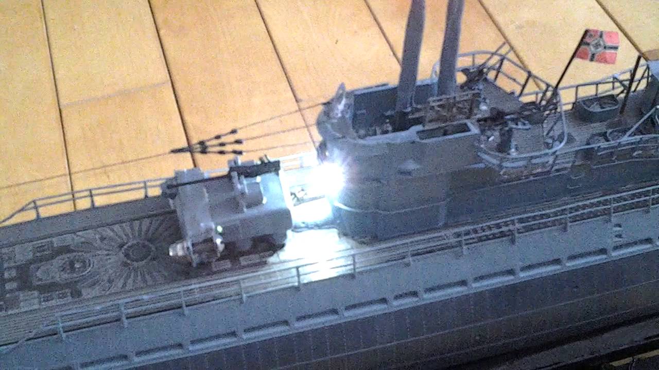
First step was grinding the hull thickness at the drain holes on the hull halves to open them up. I used a Dremel with flexible drive, a 40 watt bulb and a dark room. This worked great. After a fashion, you could tell just how thick the plastic was by the light shining through. This worked so well, I was able to leave the frames in the freeing ports. I have not found any other pictures of RC conversions of this boat that left the frames intact. They all were ground out. :(
Next I worked on the shafts. The factory shafts are 3/32" and I could not find any shaft systems less then 1/8". Here is how I bored out the 3/32" shaft hole to 1/8". I taped together the shaft fairings and struts to the hull. Then I made a boring bar. This is something I used in my profession quite often. I have been a boat designer, builder, repairer my entire life. When a customer wanted to upgrade their power, they needed to upgrade the shaft size. A boring bar uses a pilot that is the original size of the hole, connected to a cutter that is the size of the new shaft.
For the model, I used a 3/32" brass rod as a guide. The boring bar was made from a 1/8" brass tube with teeth filed in the end like a hole saw. I bent the teeth out just a tiny bit to give some clearance. With the 3/32" rod inserted into the entire length of the shaft hole, I slid the 1/8" tube onto the 3/32" rod from the aft end and turned the tube by hand to begin cutting the larger hole through the struts, down the fairing and through the hull. This was slow painstaking work, but it enlarged the original shaft hole with perfect alignment.
Next I made thrust bearing beds out of HDPE similar to David's. I used an 1/8" wheel collar on the aft side, with the set screw ground down so it would not hit the hull (things are pretty tight in that area). I first ground down the solid part of the set screw as much as I dared, so that I could have as much hex grip as possible for the allen wrench. I also made a flat spot on the shaft to get even more set screw length. On the forward side, I used a Dumas dog bone shaft coupling. This took care of forward and reverse thrust.The great part about this is the whole thing is lubricated by water!
Next I made clearance in the keel area for the rear dive plane control. The control mechanism was made as thin as you possible could make it. All made from thin brass flat stock. I wanted to have the full 60 degree movement, so the entire works are buried in the keel. The pivot pin holes in the control fork were countersunk on both ends and the pin carefully riveted into place. This way, everything was flush and thin as possible.
The pivot shaft was made from square bar with the center section left square and the ends rounded. I filed a square hole in the pivot arm. With the ends a friction fit into the planes, I am able to remove the entire works at any time. No trapping hardware in place when the hulls are glued together.
Next came the rudders. I formed a block of HDPE that held the rudder shafts. Connecting twin rudders presents a challenge to get them to move together in the same direction. I solved this by using ball link hardware and making custom horns from wheel collars and flat brass stock. Everything is tight, no slop anywhere.
The bow planes were the easiest. Round shaft with brass tube for bearings and another wheel collar/brass flat stock horn. The control rod attachment was again a ball link. I've been using ball links for 40 years in my model helicopters. They are awesome! No slop and are able to rotate in a wide range of directions. The bow planes are a friction fit to the shaft, so can be removed anytime.
I did have an issue with the deck hold down magnet system. The magnet beds along the middle of the hull interfered with the installation of the WTC. I was either going to break the hull or bust off the magnet beds. I decided that, in that area, I would glue some tabs on the underside of the deck to form a U shape that would grip the deck flange.
I have to thank David for breaking the ground before me and making my conversion much easier.
David Merriman has a great 10 year old thread https://forum.rc-sub.com/forum/gener...pe-9-it-starts on this build, so I will only go over the highlights and deviations from his build.
First step was grinding the hull thickness at the drain holes on the hull halves to open them up. I used a Dremel with flexible drive, a 40 watt bulb and a dark room. This worked great. After a fashion, you could tell just how thick the plastic was by the light shining through. This worked so well, I was able to leave the frames in the freeing ports. I have not found any other pictures of RC conversions of this boat that left the frames intact. They all were ground out. :(
Next I worked on the shafts. The factory shafts are 3/32" and I could not find any shaft systems less then 1/8". Here is how I bored out the 3/32" shaft hole to 1/8". I taped together the shaft fairings and struts to the hull. Then I made a boring bar. This is something I used in my profession quite often. I have been a boat designer, builder, repairer my entire life. When a customer wanted to upgrade their power, they needed to upgrade the shaft size. A boring bar uses a pilot that is the original size of the hole, connected to a cutter that is the size of the new shaft.
For the model, I used a 3/32" brass rod as a guide. The boring bar was made from a 1/8" brass tube with teeth filed in the end like a hole saw. I bent the teeth out just a tiny bit to give some clearance. With the 3/32" rod inserted into the entire length of the shaft hole, I slid the 1/8" tube onto the 3/32" rod from the aft end and turned the tube by hand to begin cutting the larger hole through the struts, down the fairing and through the hull. This was slow painstaking work, but it enlarged the original shaft hole with perfect alignment.
Next I made thrust bearing beds out of HDPE similar to David's. I used an 1/8" wheel collar on the aft side, with the set screw ground down so it would not hit the hull (things are pretty tight in that area). I first ground down the solid part of the set screw as much as I dared, so that I could have as much hex grip as possible for the allen wrench. I also made a flat spot on the shaft to get even more set screw length. On the forward side, I used a Dumas dog bone shaft coupling. This took care of forward and reverse thrust.The great part about this is the whole thing is lubricated by water!
Next I made clearance in the keel area for the rear dive plane control. The control mechanism was made as thin as you possible could make it. All made from thin brass flat stock. I wanted to have the full 60 degree movement, so the entire works are buried in the keel. The pivot pin holes in the control fork were countersunk on both ends and the pin carefully riveted into place. This way, everything was flush and thin as possible.
The pivot shaft was made from square bar with the center section left square and the ends rounded. I filed a square hole in the pivot arm. With the ends a friction fit into the planes, I am able to remove the entire works at any time. No trapping hardware in place when the hulls are glued together.
Next came the rudders. I formed a block of HDPE that held the rudder shafts. Connecting twin rudders presents a challenge to get them to move together in the same direction. I solved this by using ball link hardware and making custom horns from wheel collars and flat brass stock. Everything is tight, no slop anywhere.
The bow planes were the easiest. Round shaft with brass tube for bearings and another wheel collar/brass flat stock horn. The control rod attachment was again a ball link. I've been using ball links for 40 years in my model helicopters. They are awesome! No slop and are able to rotate in a wide range of directions. The bow planes are a friction fit to the shaft, so can be removed anytime.
I did have an issue with the deck hold down magnet system. The magnet beds along the middle of the hull interfered with the installation of the WTC. I was either going to break the hull or bust off the magnet beds. I decided that, in that area, I would glue some tabs on the underside of the deck to form a U shape that would grip the deck flange.
I have to thank David for breaking the ground before me and making my conversion much easier.

Comment