-
Last edited by GwenB; 12-25-2022, 08:19 PM. -
What do you think of the rudder placement like this?
Comment
-
You've over-stabilized the boat about the yaw axis. Too much vertical surface area at the stern. Drop the dorsal skeg, which eliminates the upper rudder bearing, which invites you to move that rudder down as I suggested with its leading edge hinged to the trailing edge of a lower skeg, ahead of the screw. Your most current proposal will result in a boat that will need an ocean to turn in; we want small turning radius, not big.
Now, I know I've been a bit over-bearing in this process; you are, of course, free to do as you wish. But I see you painting yourself into a corner here. You can count on me to tell you what you need to know, not tell you what you want to hear.
This is not my first rodeo.

David
Task MasterAttached FilesLast edited by He Who Shall Not Be Named; 12-25-2022, 09:07 PM.Who is John Galt?Comment
-
-
No, you haven't been overbearing at all. I appreciate your input. I'm pretty knowledgeable when it comes to aerodynamics, and hydrodynamics are essentially the same but there are additional factors that come into play. I wouldn't ask for your advice if I didn't want it =). I would like to keep working with your input to produce a design that is accurate to Verne's novel as well as practical in reality.
Having said that. From what you just said I am interpreting the definition of a skeg as a separate leading edge that is fixed in place for a control surface. Is this correct? Or is it at the root of the control surface?
Last edited by GwenB; 12-25-2022, 09:16 PM.Comment
-
Very good.
In this application the skeg is a fixed ventral vertical stabilizer and structural support for the single rudder.
I cut my teeth flying competitive gas, rubber, and tow-line free-flight model aircraft. Yes, the only difference between planes and submarines is the density of the fluids and the substitution of buoyant force rather than wing generated lift to maintain altitude/depth. Also, the similarities between Zeplin and submarine are nearly identical. An aviation background is a big plus in this game.
You're tenacious. In my book, that's an attribute.
DavidWho is John Galt?Comment
-
"You're tenacious. In my book, that's an attribute."
DavidâÂÂ[/QUOTE]
But what sort of attribute? =P hehe
But seriously, I think this may be more what you were thinking:
I'll attach a pdf so you can see it better. Nautilus-Gwen42.pdf
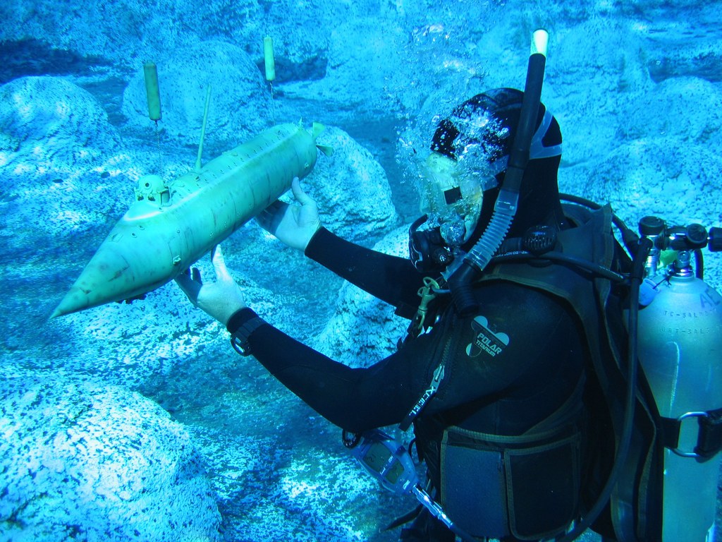
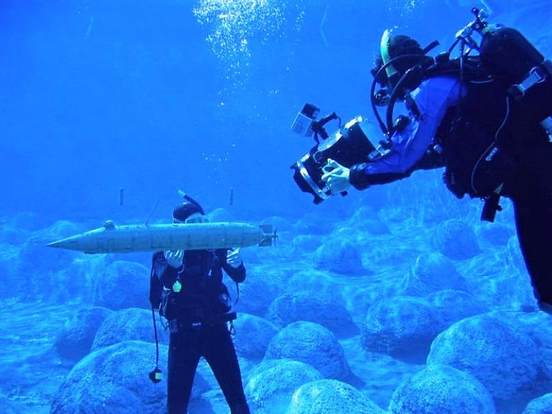
By the way, those are some awesome underwater photos you have there. Is that you?Last edited by GwenB; 12-25-2022, 11:26 PM.Comment
-
But what sort of attribute? =P hehe
But seriously, I think this may be more what you were thinking:
I'll attach a pdf so you can see it better. [ATTACH]n168015[/ATTACH]
By the way, those are some awesome underwater photos you have there. Is that you?
[/QUOTE]
Yeah, that's more like it.
Those are shots of a Civil War Union submarine being filmed. It represents an actual boat, the USS ALLIGATOR designed by a French guy who reportedly was the math teacher for one very young Juels Vern back in Frog land. Tt's a effects miniature we built and operated for a Producer of a one-hour Discovery Science Channel episode. I was topside, high and dry driving the thing.
This is me back in the day, back when I was good looking and dumber than a box of rocks.
DavidAttached FilesWho is John Galt?Comment
-
-
So David, how would you handle the control of the pitch rotation for the propeller? I know how I can use a U-joint lined up with the axis of pitch rotation to drive the prop, but I'm not sure how to move the thing up and down without the leverage provided by the control horns... About all I can think of is to run a rod into the rotating part of the tailcone that extends forward into the engine compartment and acts as a lever. But it'll be a tight squeeze to fit in next to the drive shaft. Maybe a thin steel cable or nylon cord that wraps around the hub of the pitch assembly and is anchored in the center so if the cable is pulled at either end it rotates... This is fiddly stuff now...
Last edited by GwenB; 12-26-2022, 12:37 AM.Comment
-
With no room at the tapered stern for a crank on the gimbal, you do this:
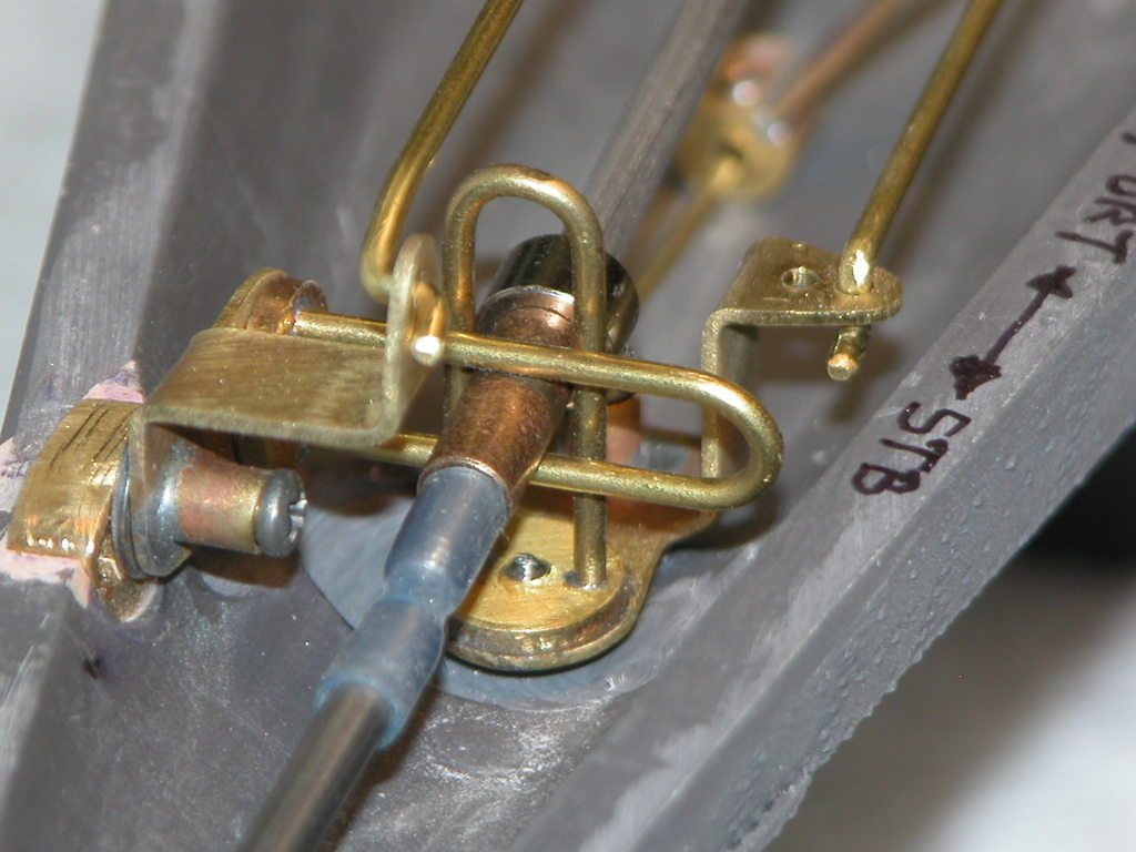
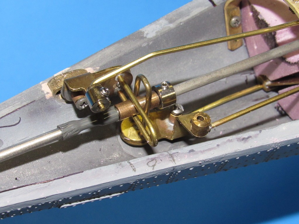


But only make it work in the pitch axis, not the pitch AND yaw axis as seen in the above photos.
David
Complexity WarshiperWho is John Galt?Comment
-
OK, that's pretty ingenius. It appears to me that the bearing for the drive shaft at the rear end is a sphere that allows the entire drive shaft to be used as the pitch control while the metal U's guide and limit movement. And I assume those gray tubes are flexible enough to allow the shaft to move up and down without torqueing the motor shaft? Also that assembly obviously does both pitch and yaw on the propeller.Last edited by GwenB; 12-26-2022, 01:04 AM.Comment
-
Comment
-
Ah, a foam layer cake, you say...
I have used this method for 3 boats and found it to work great. I draw out the station formers in 3/4' intervals (or the thickness of the construction foam that you are using ) and include alignment and center lines at 90 degrees-it might take some extrapolation, pencil and divider work. Then they are photocopied to scale size- Minus the thickness of the fairing material (I use spackle, redlead and Bondo polyester body putty - allow 1/8") and cut out. I buy a small roll of .005" aluminum flashing at Home Depot or Lowes and using 3M 77 spray adhesive, I glue the paper formers to the flashing by only spraying one side (a tack gluing) Then the templated aluminum station formers are cut out with an ordinary scissors. Next using 3/4" construction foam (either green (Lowes) or pink (Home Depot) , I glue the formers to the foam with an alignment mark on two edges for visibility .(note that this foam cuts well with any powered saw and sands well with a belt sander (preferably bench type)...
Now I take the foam former blocks and glue them, together taking care to keep everything aligned using the marks that you drew earlier. Note that by spray gluing only one side and NOT waiting until the glue is tack free, you can pull the glued items apart if needed.
The only tool you might not have in your arsenal can be easily built , purchased or borrowed-a hot wire foam cutter.
Take the hotwire cutter and using the roof flashing as a guide, proceed to cut the hull to the desired shape.
From now on its standard body work I personally like to fair the foam out with regular spackle-it sands nicely and takes paint well. I prime and paint (Old school Rustoleum is my choice-it will withstand many solvents when fully cured) I suggest drawing in a casting line so you know where to submerge the master to, so it can be removed from the mold. If the ultracal cures over past the widest point of the hull its not coming out of the mold (if so ...chisel and hammer)
Several coats of wax and/or a parting agent and you're ready to cast 1/2 at a time ..I do 1 offs with ultracal 30 but any casting compound will work-
Below is the nose fairing on my Atlantis Sub and the hull of my Pacemaker express sport fisherman (sorry I don't have more pictures of the process)-Best of luck-BG
Last edited by Bob Gato; 12-27-2022, 03:21 PM.Comment


Comment