Welcome to our forums. For the best in R/C submarine kits, components and accessories, be sure to visit the Nautilus Drydocks
If this is your first visit, be sure to
check out the FAQ by clicking the
link above. You may have to register
before you can post: click the register link above to proceed. To start viewing messages,
select the forum that you want to visit from the selection below.
ZB-1, ZB-2: Scratch Build Cylinder design for limited Production by Zero Bubble.
I have been looking at the photo of how you have set up an ESC as a test bed for testing your motors. I noticed that you have used a servo tester as the throttle for the ESC. Clever, could I get a schematic of that?
I was last working on the rear tray for the cylinder. After this I needed to get hold of an ESC to start with the Electronics layout. I'm just waiting in an Mtroniks to come my way. In the meantime I have cut out and started the template for the forward tray. This one is shorter than the stern one as it principally just holds all the Ballast tank controls.
After cutting out the paper template and then cutting out and folding the sides of the aluminium sheet I could then mark out the holes and drill for the attachment points that fit to the two side arms that are molded into the front end cap.I have actually cut the front edge a little short so that wires from underneath could fit up and be accessible from the top of the tray.
Ballast tank servo holes cut into the tray and a standard metal geared servo installed. As mentioned previously, my Ballast tank system is very simple. I have done this so that prospective
customers can set it up easily and adjust as necessary. Once the servo is secured down, then It is a matter of adjusting how the pinch will occur. This will mean working out how to place the nitro tube as it wraps around past the servo horn. Developing a roller for it and also a means of securing and accurately placing the pump micro switch.
I have made a basic design for a bracket to hold the nitro in place, however I do not know if I will redesign this later into something that can more easily be molded. For now it will give me an idea about location. At the moment it is made out of some acrylic pieces glued and bolted down in place.
I haven't yet put the backing board to support the pinch operation of the roller arm. That will come next.
I have taken a break from doing the Trays. I have decided along with everything else to produce a some magnetic coupling holders. I have been using magnets for some time after deciding to ditch the electrical connectors that act as a clamp and have to be screwed tight all the time. These clamps also doing flex and bend with the radial movement of the pivot.
Once again I would make the magnet holders out of Polyurethane resin from a series of molds. So I took some Stainless bar and then turned holes in either end, one for the push rod and the other for the magnet to slip into.
Then make sure that they fit on the prototype.
I made six of them so I could mold as many as I could in one go. Once again cut out the splitter board and position the parts. Then the air vents and the channels. Done this so many times before.
Magnets at the top create the hole for the magnets, short brass extensions at the bottom create the right diameter hole for the brass pushrod.
Yellow Play-Doh once again to create the funnels for pouring.
Then the finished urethane couplings with magnets inserted and fitted to push rods. You just need to make sure that the magnets that meet from the control surface runs are not going to repel.
Getting back to the ZB-2 assembly. I'm not to happy with how the Aluminium trays have worked out. I need to get some templates worked out so that I can get them more consistent. After this I started development work on the Ballast tank servo pinch arrangement. However I will document that later. Anyway I have decided to give the trays and their development a rest and look at starting the stern end cap design for the ZB-1, The single shaft.
I have bought a whole series of different spur gears and pinions to play around with. The single shaft design will feature a reduction gear.
Once again, start off with a Renshape blank that is turned down to round on the lathe. I have decided to bypass the production firstly of a prototype to test in the water. This is because I have decided to use the same watertight seal combination as the ZB-2. I don't know if this is unwise but I am confident that the actual arrangement of the gear housing will be waterproof. David, I'm sure will tell me in no uncertain terms if I am deviating from the ways of true enlightenment. As a result I will be machining down this end cap to within the specs of the final end cap. Slightly over sized to compensate for the differing ID's of Lexan.
After getting the end cap down to the dimensions that I wanted I could start working on the internal set up and motor mounting arrangement. I generated several drawings over a period of a couple of days to determine the best set up from the perspective of reliability, accessibility to the gears if needed and sealing. I decided that I could mount the motor inset of the rear face of the end cap. this gives stability and helps to get a precisely straight mount to the motor and also allows the short shaft from the motor to be able to stick out far enough for the spur gear to engage with the larger gear. Why do motor manufacturers not make the motor shaft longer!
Here you can see its a tight fit for the motor assembly. Off to the right is the main shaft. A flanged Oil-lite 6 mm bush and a larger nylon spur gear. This will engage with the pinion that is fitted to the
motor shaft. The output shaft protrudes dead center out the middle of the end cap. The motor face comes within about 2mm of the outer face. The bearing at the front of the motor extends out and makes for a tight fit. I will then later mark out and drill the
here you can see the main 6mm stainless steel shaft. This will be taken down a little to conform with the same 4mm shafts of the ZB-2 as it will pass through the same sealing design.
Here you can see the larger gear engage with the pinion from the motor mount. The gear ratio off the top of my head is about 5:1. The oil-lite bearing is butting up against the outer face of the end cap and needs its own housing. The pinion gear fit on the Motor is extremely tight. I haven't been able to source metal pinions so far at a reasonable price so I cam going for these nylon ones. the mesh between the two is excellent. I quite like the design of the larger spur gear and that it has the narrower longer extension that will easily allow a drilled hole for a small brass wire to lock the gear in place and eliminate slip on the 6 mm shaft.
This photo shows the machining of the back stop mount for the rear of the 6mm shaft and the Oil-lite bearing that holds the back end. I have to say, even though I have a metal lathe I much prefer turning Renshape and plastics. Acrylic and Acetal are my favourites. Anyway I cut off the Renshape ring and glue it down in the dead centre of the end cap.
A smoothing of filler around the outside and ready to press fit the 6mm Oil-lite bushing.
Here the 6 mm shaft has been placed inside the backstop for the shaft that supports it up against the end cap. The Oil-lite bearing protects the small Renshape collar that stops the shaft from wearing into the end cap.
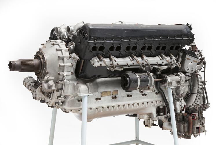
Yes That’s it. Thanks David for the prompt reply. No sneak peek, however to me the front end of what I have created and you’ll see soon enough looks more like the front end of an RR Merlin than anything else..
So as can be seen by the last post I have got to the stage of having the gear arrangement done. Essentially now its about creating the housing the gears and the mounting of the watertight section on the front. I have decided with this design not to create a whole new sealed section but will just be using the same assembly as the ZB-2 with its arrangement of shaft, oil-lite bush, inner support and outer ring with a U-cup seal. This will save development time and also I believe as mentioned last week the need to produce a working test prototype for waterproofing. At the moment the one I am working on is the one that will be used for production tooling. The only major downside is that it will stick a fair distance back from the face of the end cap.
I have been watching consistently, HWSNBN's 'Todays work' section and studying intently the shaft design and prototyping. There is so much good information here to glean from. Initially I thought about creating a housing that was quite flat and wide but wanted to differentiate from David's somewhat and so started experimenting with different shapes for the gear housing at the front. I took a flat piece of Renshape and carved it into a stylized pear shape for want of a better description, and quite liked the look of it. This piece is is a flat raised section that will sit roughly level with the gear.
The raised section has two circles cut out, one for the main gear and the other for the pinion. The flanged bush is in place to support the back of the shaft. In order to fit the gear on I had to take the 6mm shaft down just a whisker for it to be a tight fit with the gear. Further along the shaft will have to be taken down considerably to fit through the U-Cup seal and also the 4mm coupling.
Sketching always helps. Beside the compass work to get the exact numbers that you need it helps you consider ideas and find out the ideas that you had that won't work because of something that got in the way. This pic shows the existing seal design outer ring from the ZB-2. This will be used as sealing on this boat. It will safe time and whole lot of extra prototyping. What is missing is the main housing that hasn't been developed yet. This section will also receive the holes for the retaining 2.6mm screws for the motor mount. It will also take the bolts that will hold down the main outer housing piece that will cover the entire assembly.
The bolts for the motor have to be precisely spaced. When I was working on the ZB-2, I developed a small clear template that located precisely the position of the holes in relation top the main shaft. Placing this over the top meant that I could easily work out their position. It is important that access to these bolts is maintained , because you never know when you may need to replace them.
Once these were drilled and the motor fix assured I could look at the position of the holes for the main assembly. these would consist of 4 mm stainless steel bolts that would go through from the inside and have nuts on the outside. At this point I didn't quite know how the geometry on the outside would work, but we will get to that.
You can clearly see the brass pin on the side of the main gear shoulder. This was a tight fit but holds the gear in place. It ain't going to slip! You can clearly see the 2.6 mm hex bolts that secure down the motor. The two main holes that you can see here will be used to hold the main housing in place and allow access to this section if a motor, gear or shaft change is needed.
So now Its time for the outer gear housing. So I cut out a flat block of Renshape about 10 mm thick and cut it to the profile of the inverted pear shape that sits around the base. Then decided to taper it. Taking some 8- grit paper I worked my way around the sides of the piece making sure that I didn't sand too much back around the center where the seal assembly would eventually sit. I sanded a curve around the sides and pretty soon I could see this front cover piece taking shape. Over time It started reminding me of the very front end of the Rolls-Royce Merlin engine, possibly the most famous of all aircraft engines.
A thing of Beauty...
I digress. Here is the picture of the block with the outline for the base that it need to conform with at the bottom end. A hole drilled through the middle so that I could accurately line up the part and make sure I did not sand beyond the section for the seal housing.
I carefully sanded around the circular section at the front for the sealing assembly.
In the meantime I had to drill out the inside recess for the gears. After drilling out the shaft hole, I would simply drill the other holes off this as needed. Like the main gear I took a Forstner bit that was about 2 mm greater in diameter than the gear and drilled a recess of about 5 mm inside the underside of the outer housing. This accommodated the main gear.
I then had to create a small recess for the pinion coming off the motor as this was raised slightly and although would'nt need much space it would need some.
For some clever reason I put it on the side. Duhh.. Filler would later take care of this. Oil-lite bushings in place.
Here is the overall shape minus the recess and housings for the screws coming up the side from the base. The outer ring recess for the sealing assembly has been placed over the top.
I took as small chunk of Renshape and placed it into my lathe. I then turned up as small diameter that was slightly larger than the diameter of a 4 mm nut. The turned section was about 20 mm long. Taking this off the lathe I would cut two pieces with a cut line following a curve down the length of the turned shafts to follow the outer profile of the outer housing. these two pieces would be the side housings for the two stainless 4 mm bolts that run up from the base into the front of the outer housing. I then made sure that they lined up with the holes in the underside of the end cap for the bolts to go through. Drilled these holes and glues these side pieces on to the housing,
I had to make sure that they were lower then the front surface for the sealing assembly. I also had to use a Dremel and take out a little bit of the housing to complete a flat surface for the nut to seat flush on the top of the recess.
So I now have all the components for the gearbox and all the components fit. Now it is mainly down to fine fitting and surface finish. The next major step is creating a seamless smooth transition between the front housing and the raised section that it bolts into. To do this I have decided to create a wide fillet that transitions from the face of the end cap up to the edge of the raised housing. It will then continue the curve of the front housing piece as it moves up to the flat section that will accommodate the seal assembly.
The easiest way of doing this is to simply bolt down the outer housing and follow the profile of the top piece and the raised platform outline. This meant that I had to get the profile just right and to a shape that I am happy with and is symmetrical on either side. Once done I taped up the underside and outer sides of the outer housing in order to protect it and not get unwanted filler on to the Renshape of the outer housing and having to sand that off. Then I bolted this down and then started plying on the filler and wiping around with a curved filleting profile to get the over all shape.
Here the filleted filling has hardened and a thin layer that joined to the outer housing has broken free and will in turn be sanded of to form a smooth curve upward from the base of the end cap to stepped housing section around the base. All I need to do after this is to sand the fillet and get a nice consistent profile rising upward.
You can see from the varying thickness of the filler that there are areas in which the profile of the outer housing deviated from the raised housing beneath.
After sanding I then added a little more filler just to get consistency.
At this point I took the Dremel out and smoothed the section around the side of the bolt housing to make sure that the nut could sit flush. This meant taking some material out of the side of the face as it curves at its outer most point towards the bolt hole. You can just see the oil-lite bush inside of the shaft.
This close up shows that there is still a lot of sanding to be done. the nuts seat nicely on the flats of the side bolts coverings.
Here you can see the bolts extending from inside the inside face of the end cap and through the raised housing to the outer housing. You can just make out the small pinion gear of the motor. also visible is one of the holes for the motor mounts. These bolts are recessed a fair way into the inside face of the end cap. They will have some silicon squirted over the top of them to waterproof them.
Here is the assembly that fits under the outer housing. The shaft will require further reduction to fit the 4 mm U cup seal and then oil lite bushing before it.
Here is the outer ring for the sealing assembly. This is exactly the same water proofing arrangement as the ZB-2.
Here is the 4 mm Universal coupling fitting. The U cup seal will be seated just below the rim of the outer ring. I cannot fit the seal as the shaft needs to be reduced further from 6 mm to 4 mm. This orange one is the original Renshape and will be replaced with a cast urethane one soon enough..
From here on there is a lot of sanding and filling as I smooth out the fillets around the base of the raised section and also the outer housing. I have used some spray putty, sanded back and also some primer to give me an indication of low points and bumps. I am pretty happy with how the surface is looking. The next work was to look at machining down the shafts to the 4mm so that the U -cup seal will fit and marking out the two holes above the gearbox for the push rod glands.
One of the things that I am having to as certain , mostly through Trial and error is the amount of friction of the lip of the U-cup seal in the gland. What diameter should I make the shaft exactly as it meets the lip of the seal. Too much will seal really well, but the friction could pull too many amps for my liking. These U-cups are rated for a 4 mm shaft. However I have found that I really need to machine the diameter to about 3.95 mm. This gives a smooth lip that contacts well but does not create too much friction. As a result I have had to measure a section of about 2-3 mm at the 3.95 mm. The rest of the reduced section is at about 4 mm. This the is dia needed for the oil-lite bearings that will sit over the rest of the shaft.
Once these diameters are down to size I could dry fir all the components and see how the whole assembly would look. After this I started on the location of the two holes for the push rod seals. Like with the
shaft seals I am also using the small push rod seals that I designed and now produce the same as seen on the ZB-2. So after marking out the holes for the seals I could dry fit them.
As you can see the holes intersect with the up curve of the fillet. The seals have a raised outer edge that in order for them to be pushed right in and be flush with the base of the end cap will bee extra recessed space. So I will need to Dremel out a wider round section around the circumference of both holes in order to make that work.
The holes have a flat section around the fillet in order to accommodate the wider rim of the outer end of the seal barrel.
The next part of work is superfluous however I couldn't resist a bit of branding. So like the ZB-2 I have created a "ZB-1" type face recesses in the end cap. However I realized that there just wasn't the space in the end cap itself to place this so I decided to create one that would fit over the front top of the outer housing. To do this I got into my trusty 3D program of choice, Blender and wrapped recessed type into a curves surface that as best as I could tell followed the curve of the front housing.
Here is the printed 3D type face that will be recessed into the front housing and give text to the end cap. I measured where I wanted it to go and with a Dremel made short work of the soft Renshape.
I then filled the cavity with an amount of filler and pressed it in. Then wiped off the excess.
I'm now at a point where all the components have been built and It is mainly just a case of fine tuning the parts. I initially started by giving all the parts a light resin coat in order to seal them. Then lots of filling and sanding down the parts to a fine surface. At this point I will be using a combination of spray putty, filler,sandpaper and grey primer to see the surface gradually smooth down to what I need it to be. This the final stage of processing before looking at creating the molds out of silicon and i want the surface finish to be really smooth and consistent.
So I have filled and sanded around the "ZB-1" lettering, I needed some extra spray putty to fill in the grooves of the laminated around the label. I also took some fine paper around the flat round surface where the nuts for the clamping bolts sit either side of the outer housing. Firstly filler and then lots of sanding to find the low points by sanding off the high and then filling more in the areas that ain't sanded. I have had to get some rolled up sand paper into the lower widened curved sections below the holes for the push rod seals.
After this, a coat of pray putty to re-establish a smooth surface and start again. Pull out the play-doh and start sanding.
I used some play-doh to cover over the holes in order to not have spray putty gun up the insides of the these small holes. I'm not sure if the cracking is caused by different rates of expansion in the drying spray putty or chemical inconsistencies on the previous surface. I gave the same treatment to the inside of the outer casing. Its a bit tricky getting the sandpaper inside the rim and deep inside. Sanding back the spray putty gives the smoothest finish.
The outer housing /casing is already sprayed in primer.
This pic shows the gear and motor assembly outside of the end cap. The distance between the end of the drive shaft and the inner wall of the end cap is only about 1 mm. Its pretty thin. You can actually see a gradual increase and decrease in the diameter of the shaft. I wanted it to be consistent but it did'nt quite turn out that way. I will have to pay more attention to detail with the production shafts.
The lower rounded recessed section is for the pinion gear coming off the motor. It is deeper than it needs to be. This is near the end of the finish process although the sunlight is picking up nics and scratches that I haven't got rid of yet. The gears mesh well and the bush is a nice fit around the shaft.
Just need to trim and get a finer line around the rims of the push-rod seal holes. In keeping with the Aircraft theme ( my other great passion) The two push-rod seal holes remind me of the two holes in
the front cowl of the Fokker DR 1 Triplane as flown by Werner Voss and one Manfred on Richthofen.
In the background is the seal assembly. It'll all soon be ready for molding.
I had reached the final stages of finishing off the parts for molding and getting their surfaces just right. Setting up the molds for these end caps will be exactly just like how I did the end cap for the ZB-2. I decided to start with the outer housing for the gearbox. This part is relatively small compared to the end cap and should be pretty easy to set up. Once again I got a rectangle of MDF veneer board and marked out the placing for a 90mm PVC pipe to sit down. Although this time I couldn't find the right size PVC so some sticky tape would do! I then took the outer housing and placed it evenly in the middle. Then marked out and drilled the holes for the register points around the outside. PVC pipe works really well, I just have to make sure that the bottom is well sealed.
I then filled the inside of the housing with Play-doh to fill in the cavity on the main shaft hole. Otherwise the silicon would run inside and you would never get the part out. I also play-doh'd the holes for the bolts either side. I then created the pouring sprue for the resin once the mold has been created. This is done with balsa and some more Play-doh.
Ready for the pour however the best thing is to measure the amount of Silicon needed. Once again, using Rice is a really good technique for getting an accurate measurement. Pour back the rice in a separate container and then measure the amount on the side.
Mix up the Silicon and put some grey pigment into the mix.
Removing this mold is the easiest thing. Simply pull off the base and then push it down or up and out of the cardboard ring. Remove the play-doh from the part once its pulled from the base of the mold. Then you see the shape of the front surface of the outer housing/ casing.
I take the mold out and rub it with heaps of lanolin. I often then spray it with mold release even though this probably ain't necessary. Apply the part back inside and repeat the whole process.
I've cut a couple of grooves going up at an angle to help with escaping air trapped inside. Shown here are the two halves of the outer casing/ housing. Very happy with how they have turned out.
Notice the size of the pouring sprue. this should also allow very effectively for trapped air to escape. The fall of resin wont be that wide or big to block the opening.
End result is excellent. Light filing out of the main holes and that 's about it.
The front housing turned out really well and just needed some drilling of holes and some light sanding.I also rubbed the bottom on a flat sanding surface just to make sure that when mated up against the end cap it would seat absolutely flush with it. A little sanding around the rim and then inserting the 6mm Oil-lite bush into the hole at the front and it would be ready to take the shaft and the two stainless 6 mm bolts in the side housings.
All that remained was to create the molds for the main end cap. This would be a much bigger mold but essentially would be the same process as the ZB-2 End cap. The surface just having a little more detail. I decided to use the same molding board as I had for the ZB-2. However this would require a modification to it. Made up of two sheets of plywood, originally one was cut round and sat the face of the ZB-2 cap inside with the part line around the rim raised from the face. The ZB-1 end cap would have an extra level of raised surface in the shape of the oval section that mates with the outer housing. In order to fit this I needed to cut out the lower section of plywood to still get the end cap to fit at the same level as the previous ZB-2.
Once done the End cap would sit in place and would pretty much be held in place by the ubiquitous "play-doh" IOnce I was happy I would take some Play-doh and push it around the circular outer rim then push the end cap into place. Pressing it firmly and the scraping away the rest. Once again I placed some Play-doh in to the holes created by the attachment holes in the side of the tray arms sticking upwards.
Took it out and pressed some Play-doh into the various holes inside.
Re-positioned it inside the mounting board and did the play-doh around around the rim. Then just take a PVC pipe that's wide enough and silicon it to the base wide of the various register holes drilled shallow to the second layer of Plywood.
Give it a spray of Stoners release, even though it probably don't need it. Mix up some grey pigment into the Silicon mix. Its really sad , I really like the smell of this stuff even though
it kinda reminds me of hospitals.
Trapped bubbles rise to the surface. After a couple of hours, remove by pulling the PVC pipe off the base and pushing the big chuck of silicon out.
Reverse the process. Rub lanolin on the inside and all around the mold. Then replace the other side of the End cap. Slide the PVC pipe back over to about half of the length of the silicon section already created and then you are ready to pour.
The two silicon mold halves of the ZB-1 End cap. I am happy with the result..
After both halves were made I worked out where the place the Sprue. This was simply done by running a knife around the outside at an angle to create a funnel type entrance for the resin. It is large enough that air shouldn't get trapped and quite wide so that a reservoir of sorts has been made for extra material to wait during the initial seconds of pressure casting to work down with the collapse and crush of air bubbles. It just means a big chunk of excessive resin at the top to be cut off post casting.
Initially I assembled the cast parts to check for fit and accuracy. There are just two parts, the end cap and the outer housing. Fitting it all together making sure that the flanged Oil-lite bushings and stain less steel shaft align is crucial. A lithe sanding around the rims and then checking that the bolts line up and hey presto.
As you can see the outer flange of the end cap is somewhat rough. I haven't machined it down to the right Diameter for the fit into the Cylinder. That will come soon as I have had to also develop another end cap fixture to secure it so that I can get an accurate turn on the lathe. There were some trapped bubbles around where the tray arms come out side wards. I had to clearly drill these holes but it really shouldn't be a problem.
The push rod seals fit in really nice and tight and will be easy to seal with some silicon.
I actually found this lathe fixture easier to make than the last one. The holes seem to have better positioning and are easier to clamp down as that are not so close to the sides necessitating the need for extended shafts to raise the wingnuts above the rim with tube pressing down towards the inner surface of the end cap. Now once the unit is attached all I have to do is get the dial gauge out and slowly adjust by trial and error getting the end cap to rotate precisely centered.
Once in the right position, turn on the lathe and start shaving off the small amounts to get the end cap to fit just inside the polycarb cylinder.
I shave both diameters down however spend most of the time concentrated on the inner diameter that needs to fit inside the cylinder. The outer one is purely to get a nice smooth finish on the outside. Once the inner diameter is down to fit nicely inside the cylinder it is time to turn out the grooves that will hold both "O" rings. The difference between the inner surface of the cylinder and the outer surface of the end cap may be about half to 1mm. The "O" rings take up the difference. The depth of the Groove is determined by how much compression of the 'O' ring is needed. there is also the width of the groove to consider as well.
Another dry fitting ( no final silicon-ing of pieces) This is really final testing of O ring fit within the cylinder. All parts integrate well.
Once i am happy with all the integration of parts and a light sanding of parts, It is time for final assembly and eventual testing of the components.
Now all that has to be done is the do the final assembly with Silicon. The fist thing is to bolt the motor in place and put a tiny amount of Silicon over the bolt heads as they sit inside the recesses. Then I push the two main bolts through from the back and silicon the heads.
Then I take the outer housing assembly and run Silicon around the outer rim, ready to push the bolts through ad press down onto the main face of the end cap. The Nylon gear has already been fixed in placwe with a brass pin and the oil lite bushing in place.
I also push a little silicon into the two main bolt holes. Press the whole unit down on the end cap face.
Wipe away the excess silicon and screw down the nuts to really press the housing down. The next thing is to create the seal assembly. This is the same as that used on the ZB-2. It features an outer housing, an inner housing , then the oil lite bush that surrounds and supports the shaft. Here the lower edge of the outer housing is covered with Silicon and the whole unit is pressed down over the shaft and rotated slightly to make sure that there is an even coverage around the base.
At this point I then press down the U-cup seal over the top of the shaft. Silicon around the outside of the U cup seal and press down so that it sits on top of the oil-lite bearing
and the inner sleeve. After this I use some more silicon to press the outer cover down over the top of the unit and the whole assembly is complete. Give it an hour or two for the
silicon to completely dry and then it will be ready for testing.
The almost completed unit. I haven't added the push rod seals and shafts yet.
Initially testing is simply about seeing how the unit handles leaks without anything moving. So far so good. Stick it in the pool for a while, shake it around and then look for dribbles on the inside. I haven't intentionally pressurized it yet. (It is slightly pressurized when the caps are placed on the. The tightness of the end caps and the "O" rings are that good) But I will then get some nitro line and add a tiny bit more to see if I can tease some bubbles out.
After pressuring it is a matter of running the motors and checking for how well the U cup seals hold up.
fingers crossed..


Comment