ZB-1, ZB-2: Scratch Build Cylinder design for limited Production by Zero Bubble.

Collapse
X
 
  • Time
  • Show
Clear All
new posts
  • He Who Shall Not Be Named
    Moderator
    • Aug 2008
    • 12253

    #31
    Good presentation, David. I can guide you. Get rid of the POS holding fixture you are currently doing battle with.

    Buy a face-plate (hell, buy three!) to fit the threaded head-stock of your lathe. Modify the face-plate with threaded holes to accept the studs that will secure your blank resin castings to the face-plate/holding-fixture.

    Or, if you can't find a commercially available face-plate to screw onto the head-stock do this: Weld a one-inch diameter piece of steel round stock to a four-inch diameter disc of one-quarter-inch thick plate (farm this work out if you have to) and secure its spindle to the jaws of your existing chuck.

    Onto the face of the holding-fixture glue a piece of #100 sandpaper. This will afford the traction that will keep the work from sliding off dead-center as you do the turning.

    You are correct: you center the work on the holding fixture through the sloppy fit of the securing stud(s) -- the stud smaller in diameter than the hole in the casting, this is what gives you the slop that lets you slide the work over the face of the holding fixture.

    In practice you only tighten the retaining nut (could be a wing-nut) enough to keep the work on the holding fixture. You first rotate, by hand, the fixture and scoot the work to a rough center. You then wheel your cross-slide into the edge of the work so the cutting tool is about an eight-of-an-inch away from the edge of the work. Again, by hand, rotate the work and observe the clearance between the tool (we're using this cave-man approach so we don't have to **** around with the dial-indicator) and the edge of the work. As you identify the 'high' side of the work, you slide the work to even out the displacement between its edge and the tool.

    Once you've centered the work on the holding fixture you tighten the nut(s), set the lathes speed to low and grind away with reckless abandon!

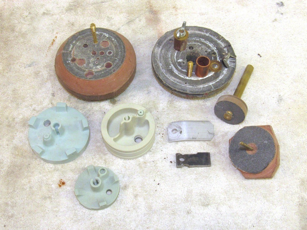
    Just a few of the specialized holding-fixtures I use to machine cast resin bulkheads. The two big ones in background employ a proper face-plate. The big holding fixture to the right features taped holes through the steel plate itself. Note that all holding-fixtures feature a piece of #100 sandpaper glued to its face – this to insure a no-slip surface between holding-fixture and the resin bulkhead being worked.

    [IMG]file:///C:/Users/David/AppData/Local/Temp/msohtmlclip1/01/clip_image002.jpg[/IMG]​


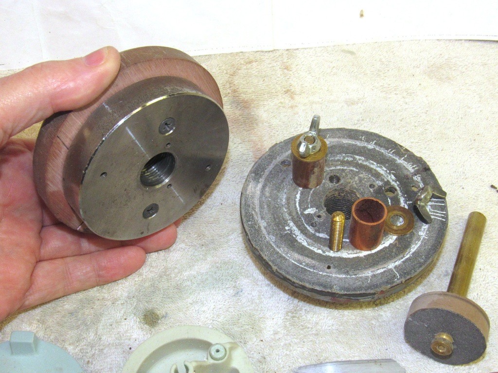
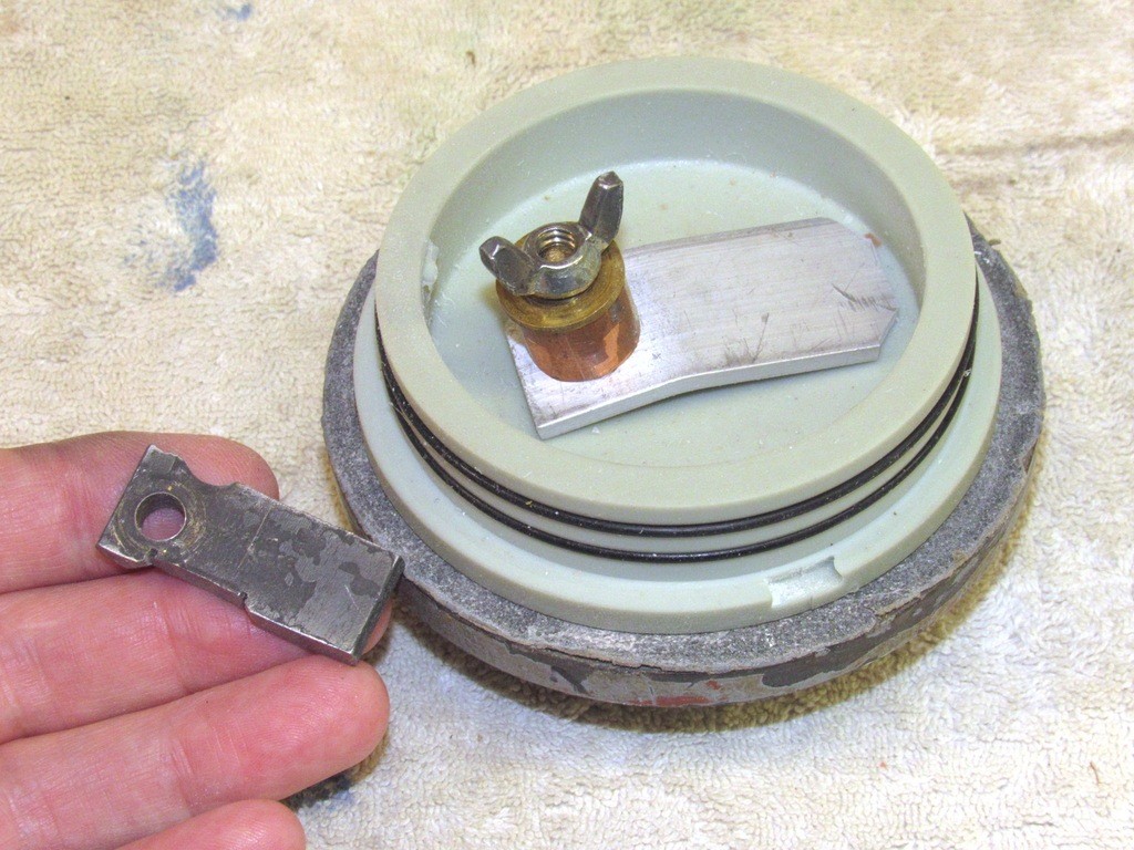
    This holding-fixture, the one in hand, features a thick hunk of RenShape screwed to it, giving me enough meat in drill and tap holes at various radius points to accept securing studs. Most of the cast resin bulkheads (internal and end-caps) have holes in them for either a conduit or to later accept watertight seals. I take advantage of these holes as I secure the work to a specialized lathe holding-fixture.

    [IMG]file:///C:/Users/David/AppData/Local/Temp/msohtmlclip1/01/clip_image004.jpg[/IMG]​


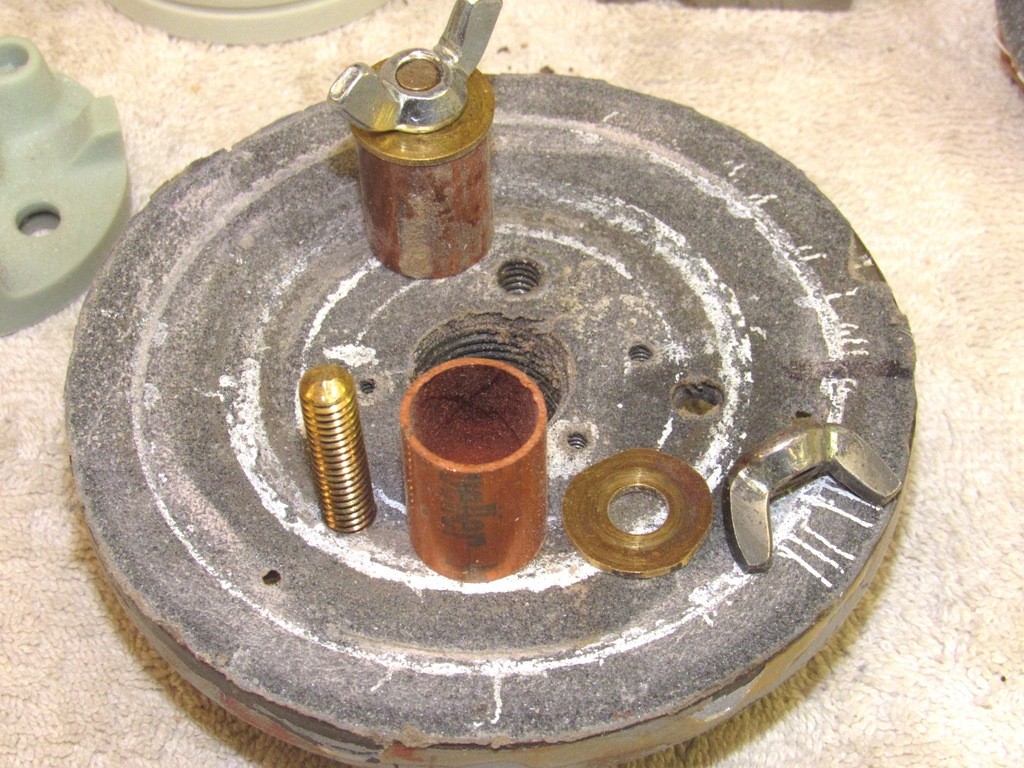
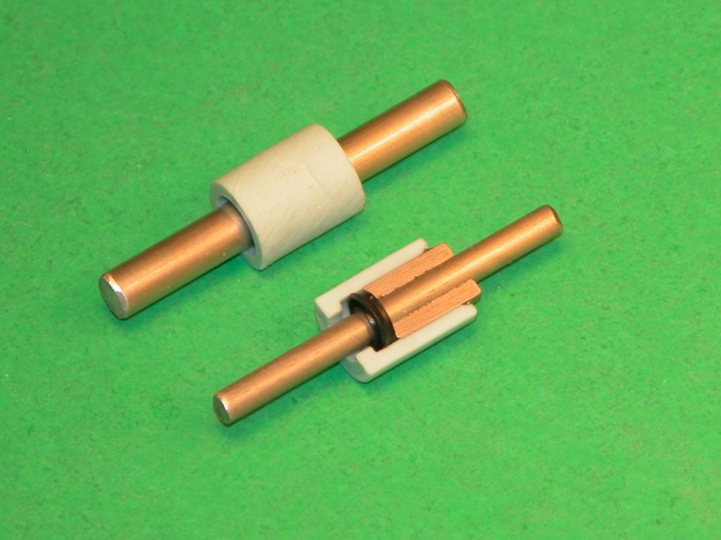
    In some cases I need to get the nut above the work. So, I use a long stud and stand-off to get unobstructed access to the nut (or wing-nut) well above the bulkhead.

    [IMG]file:///C:/Users/David/AppData/Local/Temp/msohtmlclip1/01/clip_image006.jpg[/IMG]​


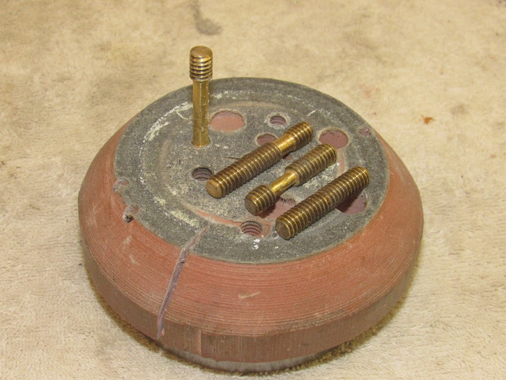
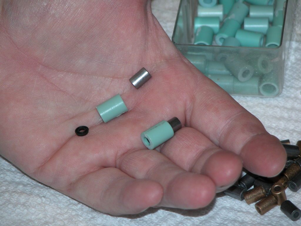
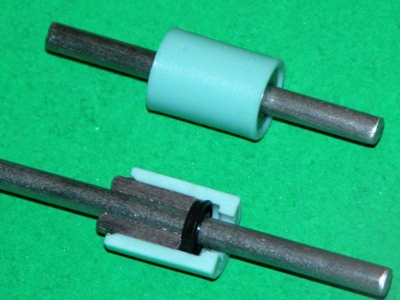
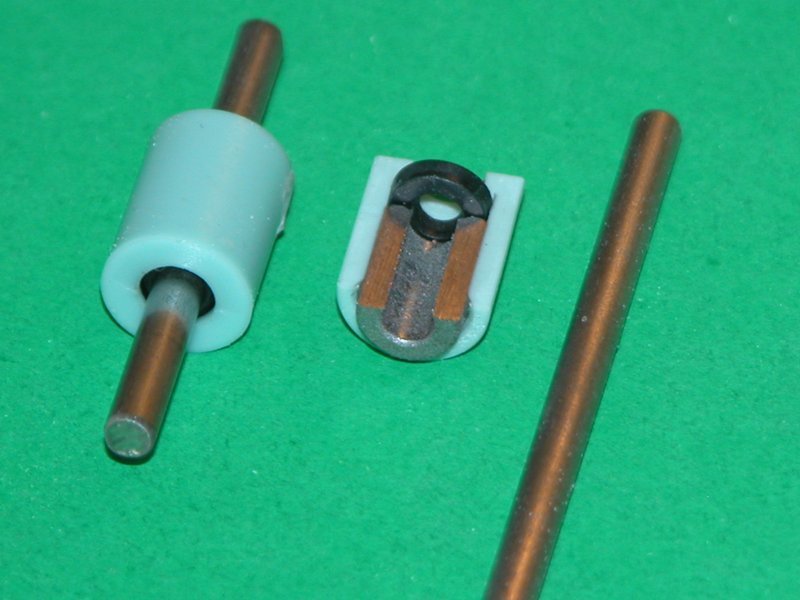
    To give me even more slop -- in which to slide the work around when on the holding-fixture -- I will sometimes shave those areas of the holding stud where it passes through the hole of the work.

    [IMG]file:///C:/Users/David/AppData/Local/Temp/msohtmlclip1/01/clip_image008.jpg[/IMG]​


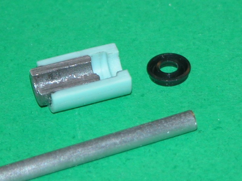
    In some applications a strong-back is used to more evenly distribute the compressive force of the nut along the face of the work.

    [IMG]file:///C:/Users/David/AppData/Local/Temp/msohtmlclip1/01/clip_image010.jpg[/IMG]​


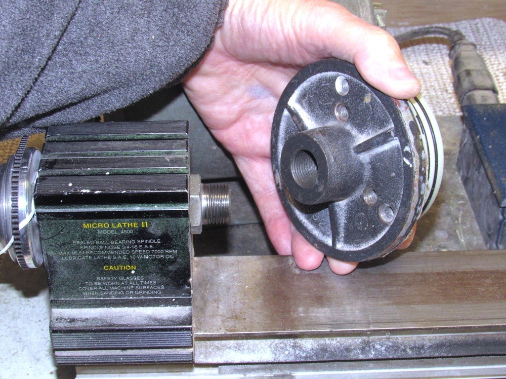
    The face-plate/holding-fixture screws right to the spindle of the head-stock. The smaller holding fixtures are secured in the jaws of a three or four-jaw chuck.

    [IMG]file:///C:/Users/David/AppData/Local/Temp/msohtmlclip1/01/clip_image012.jpg[/IMG]​
    Who is John Galt?

    Comment

    • Davidh
      Captain
      • Nov 2010
      • 719

      #32
      Thankyou David,

      I have been looking over the fixture for machining the endcaps and will sit download this weekend and will draw up some ideas about redesigning what I have. I took the faceplate out of the oily bag it came in and installed it on the lathe. The variable bolt holes are a bit wide but I can make some brackets that will clamp over a wider diameter wooden plate. There are ways around things. The main lesson I got from you however is that you make incremental adjustments to get to center by just jogging the bolts as they pass through wider holes on the endcaps. why didn’t I think of wingnuts!? Great stuff. I will come back to this one in a while.

      In the meantime I would love any further procedures you have for the shaft extensions. Do you use any jigs or fixtures to get your shafts tapped onto the motor shaft dead straight?
      In the meantime I have stripped down the original twin shaft endcap that I have been using as a test bed and cleaned up the parts. I ended up having some leaks. I thought about the silicon I used and realized that it wasn’t proper formed in gasket RTV. So I got some decent RTV Silicon and reassembled the endcap.


      Click image for larger version

Name:	3FBC1B92-95BB-4A4C-8561-29AC4DF7A0DF.jpeg
Views:	341
Size:	41.5 KB
ID:	136852


      This photo shows one of the shaft mounts done. The other shaft has the cup seal on it. The other has the cup seal smothered just short of the cup seal lip. Over this will be placed the end support cover. Currently machined out of Delryn.

      Click image for larger version

Name:	5B0906BE-1256-4974-A56F-51C24D27ECC7.jpeg
Views:	351
Size:	67.6 KB
ID:	136853

      The left over silicon from the last attempt is still evident on one side however the new silicon, a nice grey one just smothers over the top..
      All I have to do here is press the while end support down onto the silicon layer around the cup seal.


      Click image for larger version

Name:	C1332B14-BA8C-47FD-9770-E7F8392B9C99.jpeg
Views:	360
Size:	81.9 KB
ID:	136854


      There is a small gap running around the base of the closest mount. more silicon fillet.


      Click image for larger version

Name:	A58A5632-CB78-4685-AD0B-892796864E53.jpeg
Views:	362
Size:	43.2 KB
ID:	136855

      Let the silicon dry and then press fit onto the polycarbonate. Other end cap on and in the water. No leaks. I have since been testing this most afternoons after getting ho,e from school and have run the motors. Shafts turn freely. Still no leaks. I am Impressed...

      In the meantime more work on the twin endcap master.


      Click image for larger version

Name:	566DA6B5-F176-4A37-B937-492E8C233726.jpeg
Views:	344
Size:	58.6 KB
ID:	136857


      Click image for larger version

Name:	DBF79DCB-1445-4760-82EE-143EDB667CC4.jpeg
Views:	347
Size:	53.4 KB
ID:	136856


      The Holes are for the machine brass housing inserts for the push rod seals. Nice placement until I realized that their diameter would interfere with the outer diameter of the
      shaft support.. oops.. I will need to move these holes further up the arc.


      David H


      Comment

      • gantu
        Commander
        • Apr 2009
        • 360

        #33
        Great work David
        Regards Gantu

        Comment

        • Davidh
          Captain
          • Nov 2010
          • 719

          #34
          Thank you Gantu,

          I am just awaiting answers from HWSNBN regarding the shaft extensions. It is certainly a challenge designing end caps and an overall design that can be as flexible as possible to
          other builders preferences for configuration.


          Dave H

          Comment

          • He Who Shall Not Be Named
            Moderator
            • Aug 2008
            • 12253

            #35
            Originally posted by Davidh
            Thank you Gantu,

            I am just awaiting answers from HWSNBN regarding the shaft extensions. It is certainly a challenge designing end caps and an overall design that can be as flexible as possible to
            other builders preferences for configuration.


            Dave H
            I've been snowed under with recent work, but have not forgotten to work up a little primer on shaft extensions and related stuff. I'm so happy to see you extending your line of products to include the vital WTC element of the system. You've come a long way, my friend.

            David
            Who is John Galt?

            Comment

            • Davidh
              Captain
              • Nov 2010
              • 719

              #36
              Hello all,

              I realized that the push rod housings would not fit along the arc so close to the shaft support. As a result I had to move them further up on the arc and then re-drill the holes for them. I also decided to reduce the width of the flange on the outside. I reduces this by a couple of mm. This would reduce the material used but still create the stop that could help with making the units watertight.

              I haven't been able to test these brass units yet as I need to make a mold and then encapsulate the "O" ring as needed. I am very confident that they will work 100% as they are only sealing a push rod that moves back and forth occasionally.

              Click image for larger version

Name:	IMG_3325.JPG
Views:	334
Size:	62.0 KB
ID:	136955

              After a couple of extra layers of resin and sanding back the end cap looks nice. There is still some some fine sanding but getting there.

              For some time I have been looking at how I would get the tray to affix to the end cap. On my previous end cap designs I simply glued an acrylic ledge to the inside face underneath the motors and then bolted a further curved piece from there. Bolted so I could the take the whole tray off if I needed to get to the motors and take them off.

              With this design I am going to try and keep it simple. In doing so i am taking David's guidance and I am going to make the trays out of Sheet metal. This has got to be so much easier.
              I'm doing so I have had to resolve how I am going to attach the sheet metal to the end cap and this would have to happen in the space beneath the twin motors. I have noticed that
              David has simply drilled and screwed two screws into the rim of the end cap. I have decided to pretty much follow this however i will create a series of two round supports that stick out from the inside diameter. I could drill just into the rim but if I have to machine this down a fair bit from the established outside diameter of the molded piece this could give only a little material left. These two extra curves give a more secure area in which to drill and secure the sheet metal folded tray.

              Click image for larger version

Name:	IMG_3330.JPG
Views:	310
Size:	78.2 KB
ID:	136956

              As you can see I haven't yet given the inside a coat of grey primer. I've yet to fully fill the center and get it flush. What is clear form this shot in the countersunk for the motor bearing recesses. I have yet to drill the small 2.6mm holes for the motor attachments. ( why did someone at Mabuchi pick 2.6mm of all diameters? Why not 3-4mm? 2.6 is not easy to get.)

              Click image for larger version

Name:	IMG_3332.JPG
Views:	317
Size:	77.2 KB
ID:	136957

              The top holes are for the pushrods. I have two incorporated into the design and these could also be used to secure the end cap whilst machining the rims on the lathe.
              Most likely I will pass two bolts through the motor main shaft holes. Still working on that fixture. I have an idea.

              Click image for larger version

Name:	IMG_3340.JPG
Views:	281
Size:	42.4 KB
ID:	136958


              For some strange reason when I look at the end cap in this configuration, it reminds me of the front cowling of Manfred Von Richthofen's Fokker DR I. But he did'nt have two props...
              Random I know...

              Here you can see the motor shafts just protruding out of the two holes. I have yet to drill the holes that will align them better. I have found that one motor has pinched a bit in the corner so i have had to get hard with the sand paper in the corner just to free up the space for the rim of the motor as it presses hard up against the inside of the rim.


              Click image for larger version

Name:	IMG_3341.JPG
Views:	308
Size:	45.1 KB
ID:	136959

              First spray coat of primer. Yet to drill the holes around the bulges at the bottom of the rim..

              Click image for larger version

Name:	IMG_3339.JPG
Views:	310
Size:	46.0 KB
ID:	136960

              These motors have been press fit into place. Next I will drill out the holes for the 2.6mm screws.

              Click image for larger version

Name:	IMG_3343.JPG
Views:	304
Size:	55.0 KB
ID:	136961

              Drilling first holes. These little 2.6mm screws have nice hex bolts. Neat. After drilling the 3mm hole drill a small 3.5mm countersunk till about half way down.
              The motor is not centered in the hole. This hole needs to be big enough to fit the press fit shaft extension in to the motor and pass through the shaft.


              Click image for larger version

Name:	IMG_3345.JPG
Views:	298
Size:	55.5 KB
ID:	136962


              David H


              Comment

              • He Who Shall Not Be Named
                Moderator
                • Aug 2008
                • 12253

                #37
                You have so matured as a model-maker over the years, David. Keep at it, pal!
                Who is John Galt?

                Comment

                • Davidh
                  Captain
                  • Nov 2010
                  • 719

                  #38
                  Thanks David, appreciated...

                  I decided to leave the whole lathe fixture mounting for another time and that time has just come and gone.
                  Initially David took one look at the smaller block that I had fashioned up and told me to get rid of it. Rightly so, It couldn't really work. I needed a wider and bigger fixture plate to
                  hold down the stern end cap. As it was the lather face plate I have has grooves that are further out from the smaller diameter block that I had. The write up was fantastic and got me thinking...

                  I cut out a wider piece of 19 mm thick pine with a diameter of about 90 mm. Cut it round on the band saw knowing that I would eventually want to turn it nice and round. Great thing about metal lathes, they can turn wood too. I have glued a small round block on the inner side that will sit as a register point within the round hub of the face plate as it is bolted onto the shaft.

                  Click image for larger version

Name:	IMG_3366.JPG
Views:	307
Size:	69.8 KB
ID:	137022

                  So I drilled four holes around the outer rim of the block, these would hold the bolts that secure down the fixture to the face plate. Big fat washers and really tight nuts should do the job.
                  I also turned down the outer rim to get it nice and centered.

                  Click image for larger version

Name:	IMG_3367.JPG
Views:	298
Size:	78.4 KB
ID:	137023

                  After this I would take the stern end cap and place it on the other side of the fixture to work out where the screws would be drilled to get the end cap as close to center as possible.

                  Click image for larger version

Name:	IMG_3368.JPG
Views:	278
Size:	70.7 KB
ID:	137024

                  There is a hole drilled right through the center of the fixture. This would help with finding the dead center of the end cap. A mark on the end cap at dead center and then a look through the hole in the fixture to align up the hole and then mark out where the hole should be drilled to go through the biggest holes in the end cap, which are the motor shaft centers.


                  Click image for larger version

Name:	IMG_3369.JPG
Views:	299
Size:	72.5 KB
ID:	137025

                  The bolts are 3 mm dia 40 mm long. Nice big wingnuts and wide washers give plenty of movement to find dead center. I am happy with how this is looking..
                  It didn't take long to center the end cap with almost no eccentricity.

                  Click image for larger version

Name:	IMG_3371.JPG
Views:	280
Size:	73.3 KB
ID:	137026

                  Nothing to be done, just to check that I have a system that works. I can be confident now that when the cast resin end cap comes out of the mold, this stage in proceedings should work.


                  David H


                  Comment

                  • He Who Shall Not Be Named
                    Moderator
                    • Aug 2008
                    • 12253

                    #39
                    Well done, David. A reliable and easy-to-use holding fixture. Keep your fingers out of the work!

                    David
                    Who is John Galt?

                    Comment

                    • Davidh
                      Captain
                      • Nov 2010
                      • 719

                      #40
                      Thanks David. Looking forward to that write up...


                      The stern end cap is mostly done. The holes are where I need them and I am pretty happy with the arrangement. I am now going to spend a bit of time dealing with surface finish on the inside and out. However before finalising the end cap I thought about putting my 'personal touch' on it. I decided that with the end caps I would have some text embedded into the design, a negative feature that would distinguish the unit. This being the Zero Bubble twin end cap would have 'ZB-2' moulded into the face somewhere.

                      I wanted to mold "Zero Bubble model design" along the rim but found that even 3D printing a template the text is just too small, so i simply decided to go with ZB-2 along the face at the bottom and out of the way of penetrations coming in and out. I was'nt going to scribe the words in, I would stuff it up, the Text could stick out but this would cause problems for anyone wanting to drill further holes from the inside out. The unit would not sit flush on the drill press. So the text would be in relief.

                      I designed a block in Blender with the text recessed inside and then printed it out.

                      Click image for larger version

Name:	IMG_3336.JPG
Views:	281
Size:	81.9 KB
ID:	137058

                      Gave the text block a shot of primer and then sanded it back. A tiny bit of filler here and there and more sanding. Whilst doing this I outlined the area to cut out to create the recess for the text block. This was simply a case of getting out the dremel and grinding out a rectangular pattern, making sure that I didn't go to deep and cut holes out to the inside wall of the end cap.

                      Click image for larger version

Name:	IMG_3338.JPG
Views:	285
Size:	80.2 KB
ID:	137059


                      Click image for larger version

Name:	IMG_3353.JPG
Views:	278
Size:	77.9 KB
ID:	137060

                      Click image for larger version

Name:	IMG_3354.JPG
Views:	270
Size:	80.7 KB
ID:	137061


                      Click image for larger version

Name:	IMG_3356.JPG
Views:	270
Size:	77.2 KB
ID:	137062

                      Once enough material was removed I could then get the block flush and level with the face. Then I just had to center it and glue it in.
                      Once i did that I covered the text so that filler would not get into the text. Once glued down I run filler around the rim and sanded it back.

                      Click image for larger version

Name:	IMG_3357.JPG
Views:	285
Size:	66.9 KB
ID:	137063

                      To the left is the front end cap. The U shaped bracket is for mounting the 12v pump.

                      Click image for larger version

Name:	IMG_3359.JPG
Views:	264
Size:	68.3 KB
ID:	137064

                      Click image for larger version

Name:	IMG_3360.JPG
Views:	264
Size:	57.0 KB
ID:	137065

                      There is still more sanding to do around the rim. Want to lose the border around the text.


                      David H

                      Comment

                      • Davidh
                        Captain
                        • Nov 2010
                        • 719

                        #41
                        Hello all,

                        I have decided that I will be utilizing my favourite ballast system for my ZB designs. It will however be making it as flexible as possible so that if the customer doesn't want to use this Ballast system they can purchase the design that will allow for them to take the ballast system in whatever direction they wish to.

                        I have for a long time used what has been commonly referred to as the "Sheerline" system. This involves using a 12 volt windscreen washer pump to force water into a sealed tank. The air above is pressurized as is what forces the water back out when the valve is released. Energy is expended to dive and energy is released to surface. It is a slower means of diving and surfacing but I have always liked it and it is independent of needing surface air.

                        The front end cap is designed to feature a bracket that will hold the 12v pump outside. Initially in my cylinder designs a decade ago I had the pumps mounted inside however this just makes for a more crowded cylinder and extra sealing. An external mounting makes replacement much easier and quicker. The bottom mount is made of Renshape that has been cut and sanded to have a semi circle section in the middle to follow the profile of the pump. This is glued to the front face of the front end cap. Then there is a clamping bracket that holds the motor in the bracket.


                        Click image for larger version

Name:	IMG_3361.JPG
Views:	270
Size:	74.8 KB
ID:	137133

                        Initially I thought of using a Renshape outer bracket. As you can see this one is not really a great fit. I then had the idea of cutting a strip of Acrylic and sanding smooth the cut edge. Then I took a heat gun and heated the shape around the curve of the front of the pump. Then cut off the strip. A strip of masking tape protects the front of the pump from the residual heat.


                        Click image for larger version

Name:	IMG_3362.JPG
Views:	254
Size:	73.7 KB
ID:	137134

                        Then I simply have to cut two small square bits and glue them on either end. These will make the bracket. Holes drilled into them and corresponding holes
                        drilled into the bottom mount. The Bottom mount will have the bolts mounted upwards with the heads molded into the bottom bracket. Nuts will simply be tightened
                        down over the thread to secure the pump in place.

                        Click image for larger version

Name:	IMG_3364.JPG
Views:	253
Size:	68.1 KB
ID:	137135


                        Click image for larger version

Name:	IMG_3372.JPG
Views:	248
Size:	71.7 KB
ID:	137136

                        I drilled out a curved section in the sides of the bracket just as it meets the flat section above the holes. This is for the nuts and that they have enough space to tighten down
                        onto the flat surface of the bracket. The bracket has had a shot of primer but will need a lot more sanding to get it just smooth.

                        Click image for larger version

Name:	IMG_3375.JPG
Views:	246
Size:	77.2 KB
ID:	137137

                        The bottom bracket will take a fair amount of polyurethane to make it. (It will be cast). I thought about reducing the material needed for this part. Urethane is pricey.
                        So I decided to hollow out the underside. Same strength just less material. This will allow the bolt to be pushed up giving more length from a shorter bolt and allow it to be molded
                        into the piece.

                        Click image for larger version

Name:	IMG_3374.JPG
Views:	241
Size:	74.9 KB
ID:	137138

                        The thing about designing a cylinder is how flexible do you make the design in terms of options to any given customer. I have decided to make this bracket set up
                        not an integral part of the end cap so that it is simple a case of gluing on the bottom mount. There will be an outline of where the bracket is fitted to on the front.
                        One thing is for sure and that is that the pump crowds the front of the end cap. Getting all the electrical connections past it not withstanding the plumbing is fun.


                        That is for next time!


                        David H


                        Comment

                        • He Who Shall Not Be Named
                          Moderator
                          • Aug 2008
                          • 12253

                          #42
                          Good stuff, David. I see that you have become a RenShape convert. Good, clever stuff working out that bracket master.

                          David
                          Who is John Galt?

                          Comment

                          • trout
                            Admiral
                            • Jul 2011
                            • 3545

                            #43
                            Really enjoy watching you work through this. It is fun to see the solutions you come up with!
                            If you can cut, drill, saw, hit things and swear a lot, you're well on the way to building a working model sub.

                            Comment

                            • Davidh
                              Captain
                              • Nov 2010
                              • 719

                              #44
                              ​ Hello All,

                              Thanks Trout, David,

                              I have another set of questions for HWSNBN to answer, I’m still waiting for the shaft one.. ( I know you have been busy)
                              I am about to start creating the molds for the following parts. However I need to get your opinion and advice regarding the best way to set up the mold. (orientation of the part)
                              These two parts are the inner and outer supports for the motor shaft extension. The Renshape one is the Outer ring and then the Brass, the inner support.
                              I will be casting both of them out of Urethane.


                              Click image for larger version

Name:	IMG-3132.JPG
Views:	261
Size:	67.6 KB
ID:	137178

                              The masters seen here have a very nice and precise fit with the inner support just fitting into the outer ring (Renshape). I will need to be able to replicate this in a mold of these two parts.

                              So the question is:

                              I have two approaches to how I create the silicon molds for these and they are principally to do with the orientation of the part to the separation plane.
                              When I created the ring parts for the Propulsor unit of the Borei I placed the ring parts pointing upwards and molded a two part mold with the riser sitting along the top rim of the part. The separation plane of the mold being perpendicular to the part and running close to and around the lower rim. I am seriously considering this for the outer ring. Glue a very small bubble catcher along the top rim and some air vents off these.

                              For the inner support, (the Brass piece) it needs to have a precise inner ID to hold the 4mm ID Oilite bush. I don't know If I should mould this as shown in the below pic with the piece laid on it side with the axis of the piece parallel with the separation plane of the mold. Should I just have a huge 8mm insert going through the middle or should I mold it standing up like the larger outer ring that it needs to snugly slide into?

                              Click image for larger version

Name:	IMG-3516.JPG
Views:	236
Size:	80.7 KB
ID:	137179
                              In this photo the outer rim is sitting on top of the "vertical mold' for want of a better term. To the right the inner support is laid horizontally like the parts in the mold beneath it.
                              Should I mold this part (inner support) like the one on the right?

                              O.K, I hope this makes sense.

                              What are your thoughts?

                              David H


                              Comment

                              • He Who Shall Not Be Named
                                Moderator
                                • Aug 2008
                                • 12253

                                #45
                                Yeah, I've got to get on that how-to-make-a-shaft-extension piece for you, David. Thanks for being patient with me.

                                You can simplify your seal foundation by making it a simple cast resin cylinder with a bore at the forward end to accept your Oilite bearing, and a smaller bore at the after end to seat the lip of the cup-seal. On the cast resin seal foundation, from the forward end you slide in the bearing and glue it in place with CA; and from the after end you slide in the cup-seal; then you glue a washer-shapped retainer over the cup-seal to keep it in place. Finished!

                                Here's a variation on that theme:


                                KISS damnit! KISS!!!!

                                David
                                Who is John Galt?

                                Comment

                                Working...