Scratch Build Soviet Project 667 BDRM Delta IV SSBN K-18 "Karelia" Scale 1/140

Collapse
X
 
  • Time
  • Show
Clear All
new posts
  • Subculture
    Admiral
    • Feb 2009
    • 2119

    #91
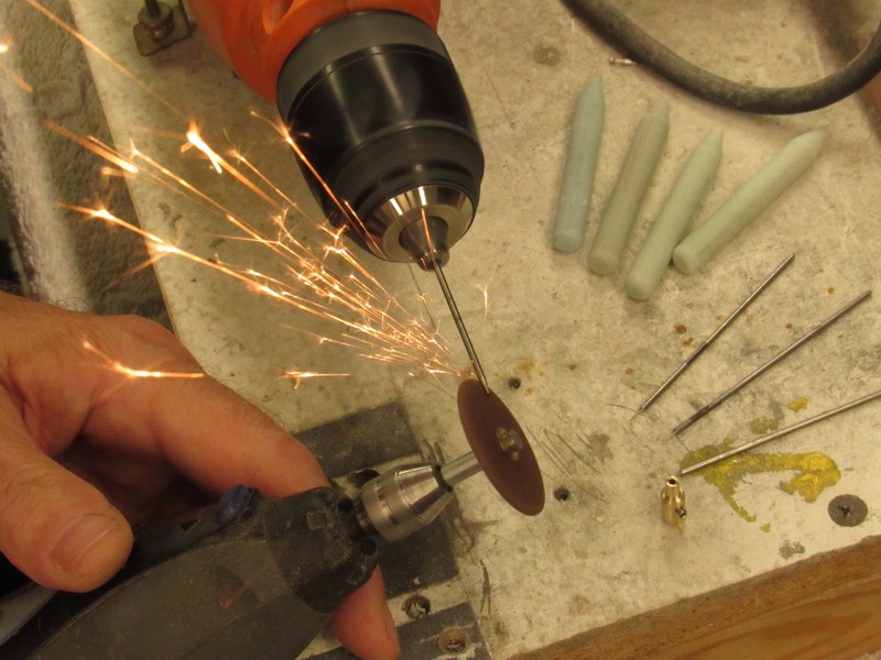
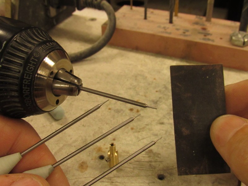
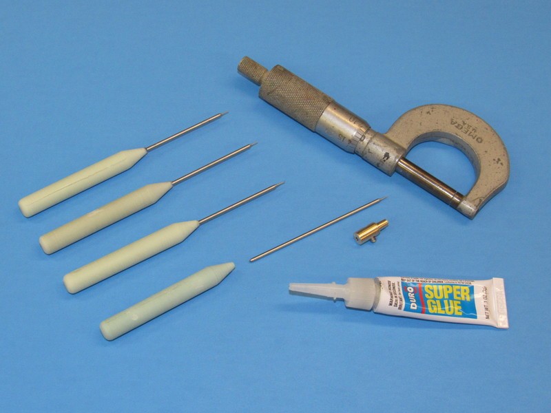
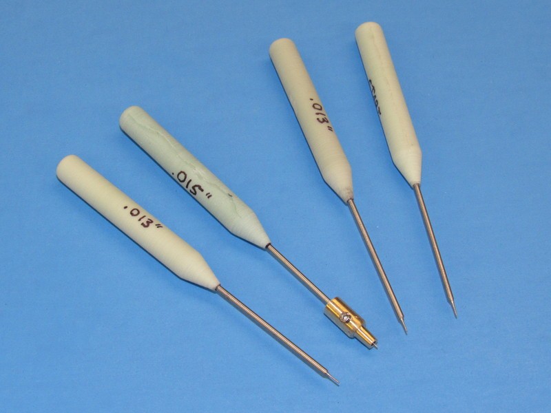
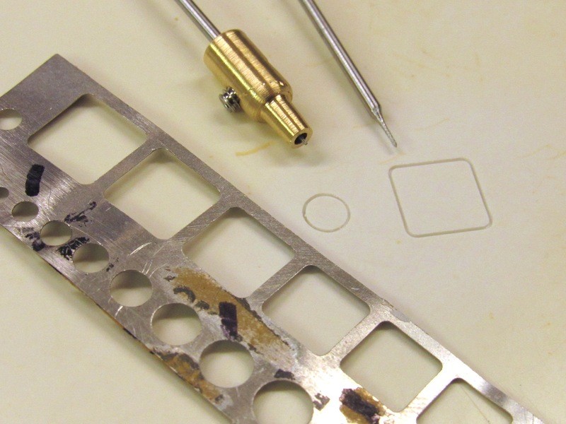
    Scribing is a pet hate of mine. I find a cured resin is the easiest stuff to cut into. Unless you're making a very shallow scribe using a tapered tool is a bad idea, as the groove will get wider as you press down, and it makes it difficult to control the line. i make parallel scribes from old junior hacksaw blades, broken xacto/scalpel blades, small srill bits etc. You can use a grinder to dress them into shape.

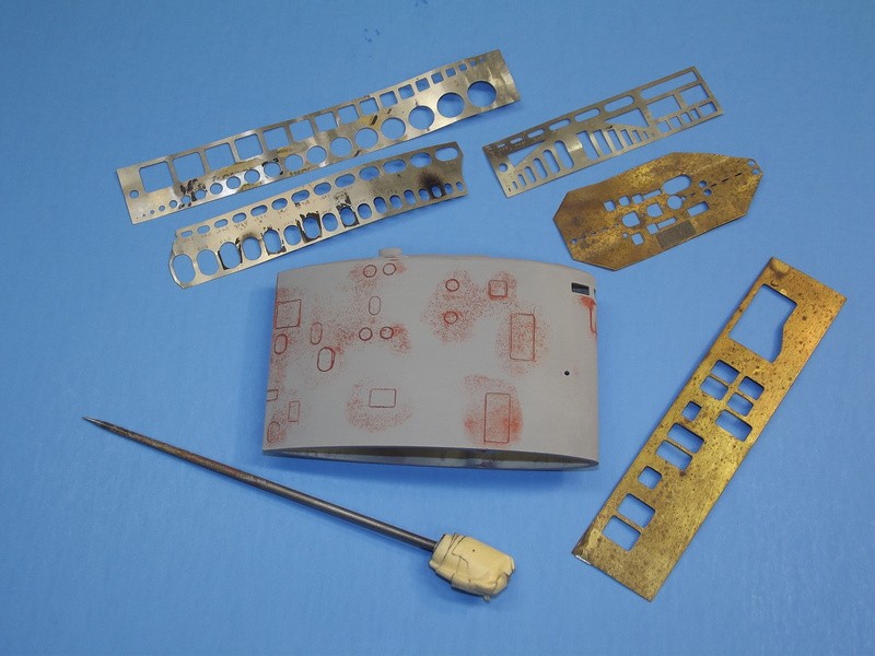
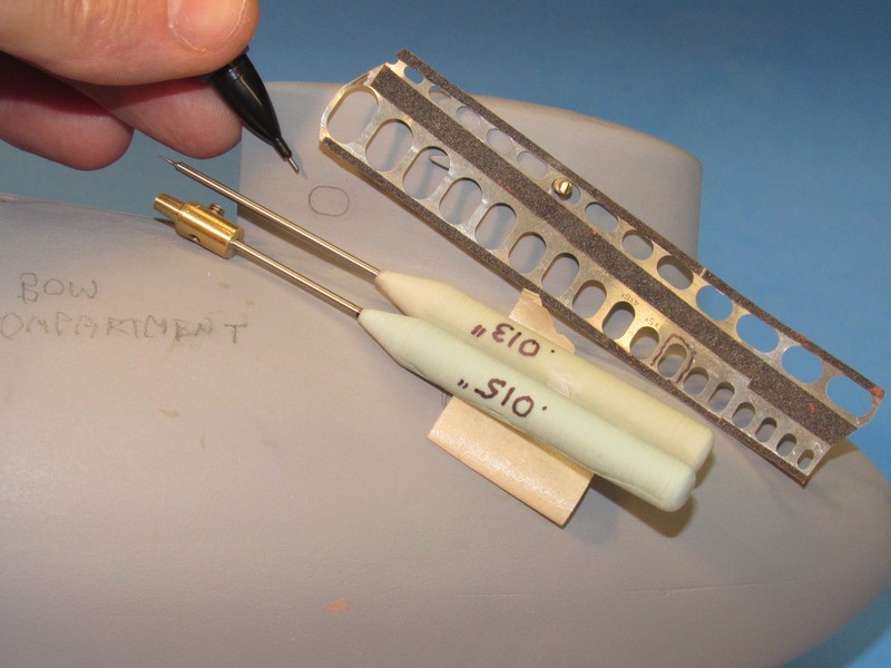
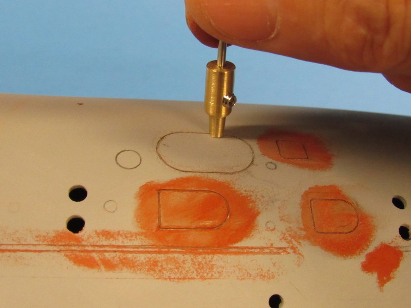
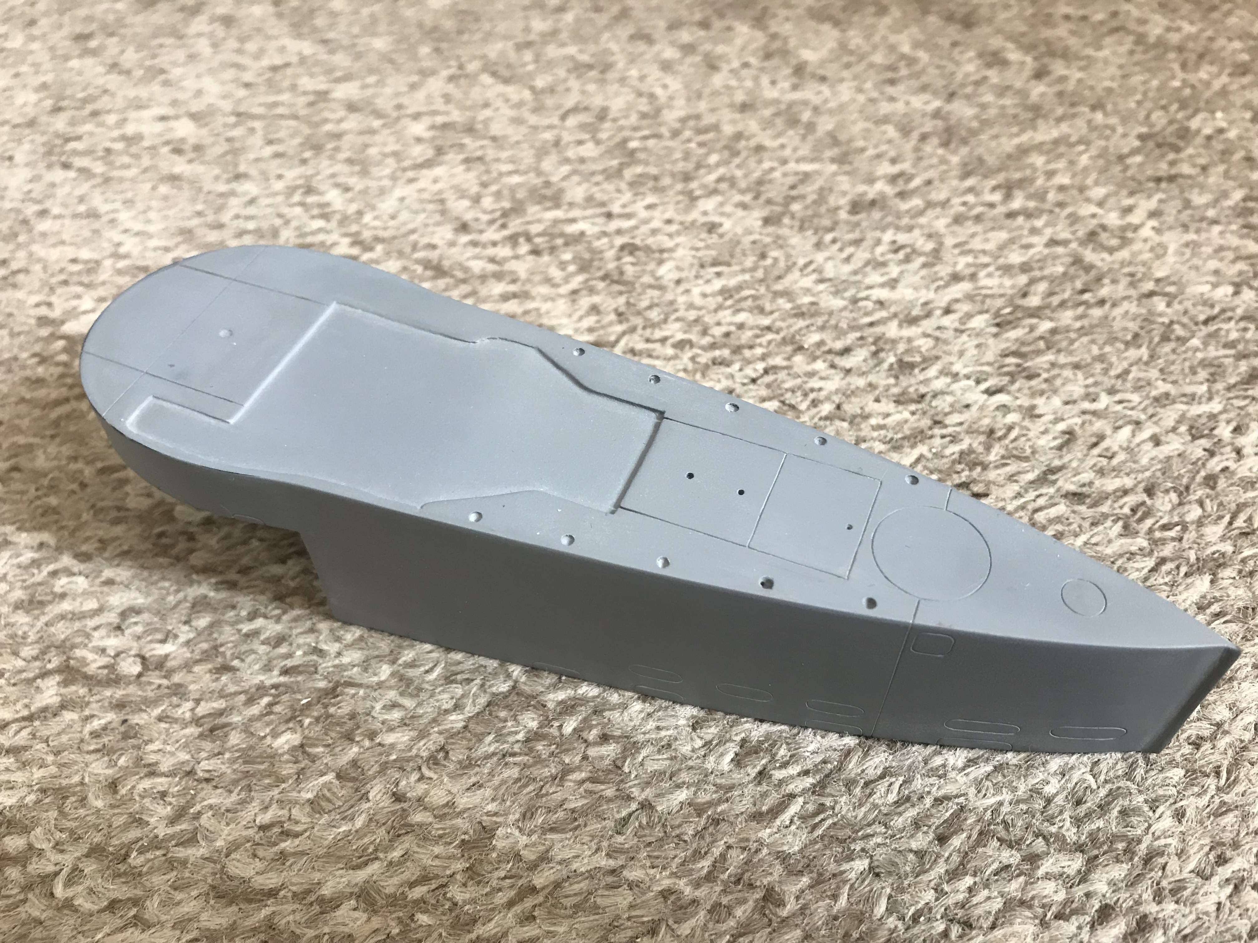
    Did the scribing of slots and hole markings a while back on 1/22 Seehund tower, not 'Merrimen zen' level but reasonably pleased with result. thankfully most my subjects of interest don't need much scribing.

    Comment

    • HardRock
      Vice Admiral
      • Mar 2013
      • 1609

      #92
      'Merrimen zen' - There's a moniker that might get quite a bit of use in the future! We are the Pilgrims, master; we shall go
      Always a little further; it may be
      Beyond that last blue mountain barred with snow
      Across that angry or that glimmering sea.


      Comment

      • He Who Shall Not Be Named
        Moderator
        • Aug 2008
        • 12253

        #93
        Originally posted by HardRock
        'Merrimen zen' - There's a moniker that might get quite a bit of use in the future! We are the Pilgrims, master; we shall go
        Always a little further; it may be
        Beyond that last blue mountain barred with snow
        Across that angry or that glimmering sea.

        **** you!

        David
        The Horrible
        Who is John Galt?

        Comment

        • bwi 971
          Captain
          • Jan 2015
          • 896

          #94
          Originally posted by he who shall not be named

          **** you!

          David
          the horrible
          .......roflmao
          Practical wisdom is only to be learned in the school of experience.
          "Samuel Smiles"

          Comment

          • trout
            Admiral
            • Jul 2011
            • 3545

            #95
            I think David is getting more crotchety in his old age (if that is even possible) LOL
            If you can cut, drill, saw, hit things and swear a lot, you're well on the way to building a working model sub.

            Comment

            • Davidh
              Captain
              • Nov 2010
              • 719

              #96
              Hello all,

              After spending a fair amount of time getting the angled rear deck transition just right, smooth and consistent, I then got to thinking about the stern hatch detail around the vertical rudder at the back. The problem that I had was that I didn't have a lot of good photo's looking straight down on the hatches towards the rear. There are quite a few photos of the these hatches from a low angle. This means that some amount of interpretation was needed to work out the geometry. These are the kind of pics that I'm talking about here.


              Click image for larger version

Name:	IMG_1557.JPG
Views:	353
Size:	154.9 KB
ID:	132452

              Click image for larger version

Name:	IMG_1382.JPG
Views:	328
Size:	156.1 KB
ID:	132453

              This back end of the 667 has a fair amount of detail as there are lots of hatches and fitting crowded into a relatively small space. These features mainly center around the recessed hatch that is angled at the front so that it is level rather than angled with the gradual curve of the rear hull. This main hatch has a couple of features that have proven a little difficult to interpret. As mentioned I have had a hard time finding good overheard shots of this hatch to mark out the structure and shape of the hatch and its overall geometry. In the center is a raised section that looks like a release mechanism, but what took me a while to work out was the semi circle plate at the front of the hatch that is raised.

              Firstly I got onto the lathe and found the last decent sized piece of brass round bar I could find. I then stuck this in my trusty lathe. I have said this before and I'll say it again, If you are a scratch builder, get a metal lathe. The best thing ever. I really enjoy turning, I'm not great at parting but facing and turning is good fun and so the opportunity to create a hatch on the lathe rather than 3D printing was always a good option. I don't get to spend as much time turning as I'd like. I drew up the hatch that I wanted to create and started machining the excess material.


              Click image for larger version

Name:	IMG_1559.JPG
Views:	249
Size:	131.9 KB
ID:	132454

              Click image for larger version

Name:	IMG_1561.JPG
Views:	241
Size:	136.4 KB
ID:	132455

              As you can see from the plan view the stern area of the 667 is a bit crowded. The turned up brass part is here after the fun that was parting off. This hatch will feature a styrene semi circle cover over the front section. A little bit of polishing and then recessed in to the back of the hull. I took the Dremel and ground out a section of the hull where the hatch would be located and also the circles where I would fill in with filler then scribe out. I had to grind the main hatch area out a bit further to get the depth required for the brass hatch piece to fit in.


              Click image for larger version

Name:	IMG_1467.JPG
Views:	230
Size:	137.0 KB
ID:	132456

              Once the filler was in with a level of over filling I could then sand down the circles and get them flat. I could them scribe the numerous circles that are in this are of the stern. I measured out the size of the semi-circle plate that would need to be fixed to the front of the hatch. I took a .5mm sheet of styrene and marked out at cut the semi-circle. I then filed it back and worked out where to glue it onto one side of the hatch.

              Click image for larger version

Name:	IMG_1567.JPG
Views:	233
Size:	565.9 KB
ID:	132457

              Click image for larger version

Name:	IMG_1562.JPG
Views:	222
Size:	595.1 KB
ID:	132459

              I noticed that there is a circular metal plate just behind the main hatch. It looked welded or screwed down to the hull. This would Ideally be replicated by creating a styrene circle that would simply glue over the top. This was also the case with a smaller circle in the centre of another scribed circle.

              Click image for larger version

Name:	IMG_1568.JPG
Views:	238
Size:	137.4 KB
ID:	132458


              More later.

              Comment

              • bwi 971
                Captain
                • Jan 2015
                • 896

                #97
                The piece that you are working on is the escape chamber......I knew I posted some pictures of it......here is the link David.
                Will keep looking for you.

                What is the extra, circular do-dad on the rear deck of the Delta. I see a hatch and a rescue buoy but what is the other one? {"data-align":"no


                Grtz,
                Bart

                Practical wisdom is only to be learned in the school of experience.
                "Samuel Smiles"

                Comment

                • Davidh
                  Captain
                  • Nov 2010
                  • 719

                  #98
                  Hi Bart and thanks for the file. There were a couple of images of the escape hatch from a higher angle that I had not seen previously.

                  I could detail up the escape hatch to the Nth degree and go for every little detail but decided at this point to get as much detail that would be seen at a distance and would still look good. I also detailed around the smaller hatch and raised it. I used a tiny piece of brass wire to give detail to the pivot arm structure at the centre of both hatches. I then pasted some filler into the recess where the escape hatch is and lowered the escape hatch in place. This should give an even squish in which I just go around with sandpaper to smooth out.


                  Click image for larger version

Name:	IMG_1573.JPG
Views:	241
Size:	565.9 KB
ID:	132589

                  Now that details have come to light from Barts pics, I will be doing a little further detail to the escape hatch. Filling in and sanding back the rim where the joint between the half circle styrene piece fits over the brass hatch. Once all the filling is in I will take some time to sand back around the rims and reduce the paper to smoother and smoother till it gives a good smooth finish with the primer. You can see this is needed just around the rim of the escape hatch. I have also added some more brass detail onto the raised hatch behind the escape.


                  Click image for larger version

Name:	IMG_1573.JPG
Views:	241
Size:	568.2 KB
ID:	132590


                  I left the back of the boat and then started looking at the development of the drainage/ limber holes in this boat. This boat has more limber holes that most so working them out and making sure that they correspond to the right place on both sides has taken some time. I marked them in place initially with pencil and then went over them again in marker pen. The biggest concentration being around the rear of the missile deck section as it angles down. They are mainly in two rows in clusters.


                  Click image for larger version

Name:	IMG_1548.JPG
Views:	237
Size:	564.7 KB
ID:	132591

                  Mostly I would be scribing in PVC pipe and filler. A lot of the limber holes occurring over area that had created a filleted curve, where the missile deck transitions into the hull. I then took out the scribe and started the slow process of scribing each individual limber hole. This is a lengthy process. Towards the back of the boat the hull transitions once again from PVC to timber so I have had to Dremel out the area where I will be scribing near the rear hatches.

                  Click image for larger version

Name:	IMG_1552.JPG
Views:	257
Size:	558.0 KB
ID:	132592

                  David H

                  Oh, By the way HWSNBN. I am awaiting the write up on scribing.

                  thanks, Dave.


                  Comment

                  • DMTNT
                    Commander
                    • Jun 2018
                    • 297

                    #99
                    Originally posted by Davidh
                    Oh, By the way HWSNBN. I am awaiting the write up on scribing.

                    thanks, Dave.
                    To obtain true enlightenment, one must make the pilgrimage to the hallowed garage in person ;-)
                    Dead men tell no tales...

                    Comment

                    • He Who Shall Not Be Named
                      Moderator
                      • Aug 2008
                      • 12253

                      Originally posted by DMTNT

                      To obtain true enlightenment, one must make the pilgrimage to the hallowed garage in person ;-)
                      Smart-ass!

                      But you're right, I did promise. I hope to knock that obligation off this weekend. Sorry about the delay, David.

                      David
                      Who is John Galt?

                      Comment

                      • DMTNT
                        Commander
                        • Jun 2018
                        • 297

                        Originally posted by He Who Shall Not Be Named

                        Smart-ass!

                        But you're right, I did promise. I hope to knock that obligation off this weekend. Sorry about the delay, David.

                        David
                        Hey! That is an honor that I do not take lightly. Still think it was incredibly generous of you and Ellie to invite me over like that. I enjoyed every minute. Thank you again for that!
                        Dead men tell no tales...

                        Comment

                        • He Who Shall Not Be Named
                          Moderator
                          • Aug 2008
                          • 12253

                          Originally posted by He Who Shall Not Be Named

                          Smart-ass!

                          But you're right, I did promise. I hope to knock that obligation off this weekend. Sorry about the delay, David.

                          David


                          David
                          Who is John Galt?

                          Comment

                          • He Who Shall Not Be Named
                            Moderator
                            • Aug 2008
                            • 12253


                            Who is John Galt?

                            Comment

                            • Davidh
                              Captain
                              • Nov 2010
                              • 719


                              Hi David,

                              Thanks for the pictures of how to do scribing and more importantly the tools to do it. Last week I took one of my small round files and pretty much did what you have shown here. I've only just started using it on the Fin that I have been working on however for the stern of the hull I haven't applied it. I will get back to the scribe work around the vents towards the rear of the boat, later.

                              I started developing the scoops that are on the rear of the hull a couple of weeks ago. I use a Dutch 3D modelling program called Blender. It is a fantastic program. It does everything and is very underrated in my opinion. So pretty soon I managed to get four scoops that are identical. Send the file to the printer and then print off the design.

                              Click image for larger version

Name:	667 scoops blender.JPG
Views:	258
Size:	129.7 KB
ID:	132701


                              Click image for larger version

Name:	667 scoops small.JPG
Views:	260
Size:	400.7 KB
ID:	132702

                              The great thing about 3D printing is that you can get identical parts very easily. Also the level of detail is quite high. The major drawback is the visibility of all the layers. It takes quite a few sprays of spray putty to blend them in none the less.

                              Click image for larger version

Name:	IMG_1671.JPG
Views:	230
Size:	409.4 KB
ID:	132703
                              The four scoops needed several sprays of putty then lots of sanding. Then more filler and spray. At the front of the inlet is a square type design that I could make out from some blurred photos and some diagrams that I have found on a Russian website. I don't have any really clear close up pics of these inlet scoops. If any one has any good close up pics of the scoops, then that would be greatly appreciated.

                              I then marked out the location of these scoops on the lower hull sides of the rear hull. After marking these out I created a profile by cutting out the shape of the flat surface of the scoop onto 1mm thick styrene. This profile would be glued onto the hull and create the outline for the scoop molded into the lower hull. I will then add a small amount of filler around the outside of the styrene profile just to smooth it over and give it a smooth transition between the two.

                              Click image for larger version

Name:	IMG_1662.JPG
Views:	222
Size:	524.2 KB
ID:	132704


                              Click image for larger version

Name:	IMG_1677.JPG
Views:	226
Size:	506.9 KB
ID:	132708


                              Click image for larger version

Name:	IMG_1673.JPG
Views:	194
Size:	517.1 KB
ID:	132705

                              Click image for larger version

Name:	IMG_1678.JPG
Views:	211
Size:	489.5 KB
ID:	132706

                              Click image for larger version

Name:	IMG_1675.JPG
Views:	224
Size:	522.2 KB
ID:	132707

                              As can be seen these scoops are in line. What look like outlet ducting alternates between the two. If anyone has pics of these that would also be greatly appreciated. I have yet to design these so any inspiration beyond the grainy pics and line drawings would be greatly appreciated. I intend on drilling a small hole into the flat base section of each scoop and then drill a corresponding hole into the molded profile at the right spot to put a small stainless screw or other mechanical fixing and not just rely on a glue fix that could easily snap off when the boat is being moved around on the bench.


                              David H

                              Comment

                              • Subculture
                                Admiral
                                • Feb 2009
                                • 2119


                                That's neat, don't recall seeing that in the past. I take it that limits the depth of the scribed lines to make them uniform.

                                Comment

                                Working...