Ok, I'll try...
David, fabulous work. Now take what you've learned, throw the entire project in the trash, and start over again. Only do it better this time.
Watching in eager anticipation!
-
I like the look. It's mean. It's rough. A Soviet Boomer should look like that.Leave a comment:
-
Your engraving work is still awful! For god's sake!
You've so improved your lay-out, and the symmetry of your work has gotten much better. As has has your methodology.
But, you have not done a god-damned thing to improve your engraving work. I've presented the process to you - in excruciating detail! STUDY IT! PRACTICE IT! LEARN IT! You will be the better model-builder for it. Wood is not your friend when it comes to using it as a scribing substrate.
Others are too weak-knee to give it to you straight. I will. Always. You have potential. I see it. Now, you must achieve it.
Get on with it.
DavidLeave a comment:
-
Hello all,
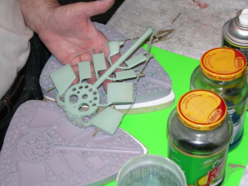
So I have finally got around to doing some more work on the 667. I am at the stage where I will be spending time just going over all the little points of the design to find blemished and inconsistencies and smoothing them out. However for some time I have been meaning to complete the deck railing/ safety track that runs along the bow section from the front of the fin towards the torpedo loading hatches up the front. I would be making them of the same styrene that I have been using for the rear decks.
So I measure out and cut the two fine pieces of strip styrene and then mark out where they are located on the forward hull, just along the ridge line where the hull slopes down from the flat deck section. One is longer than the other. I dribble superglue along the length of the strip and glue it down. making sure there is no wavering.
After this I started looking at the interface of the sail and the front of the missile deck. Currently there are gaps where the back of the sail is slightly higher than the missile deck. I wanted to make sure that the fit between the deck and the fin would be snug and really precise. I had also noticed that the fin does not sit absolutely level with the its rear end sitting slightly high. I needed to cut a little further out of the back of the fin so it would sit level. After doing this there was a bit more of a gap. The best way to get the two pieces to have a really close and tight fit would be to use filler applied and then separated from one of the surface, this would be the missile deck. So I took some masking tape and placed it over the top of the missile deck around the area in which the fin would be located, this incluide don the top and down the sides of the missile deck. The aim being that the filler would attach to the fin. Then I positioned and strapped down the fin to the exact spot I wanted it to. Mixing up filler I then applied it around the gaps where the two met.
I then mixed up filler and applied it around the base of the Fin, pressing it in underneath the rear of the fin and then down the sides of the flanges as they angle outwards to meet the wider front of the missile deck. I packed in more than needed so that I could sand it back and get a really smooth, fine and consistent part line. The masking tape will act as a release agent of sorts hopefully allowing for a clean break.
After packing in the filler and letting it dry, I then sanded back the filler so that it would be smooth and complete the transition between the fin and the missile deck. I also sanded down the sides of the flanges to give as smooth a transition as possible between the forward sides of the missile deck and the back of the fin.
David H
Attached FilesLeave a comment:
-
-
Hi Brady,
thanks for the compliments. I haven�t done too much more on her as I have been busy with orders and also this weekend I will be attending a hobby show here in Sydney. After this weekend I intend to start up again. Good timing as we are heading into ideal fibreglassong weather as the temperatures start rising...
Dave HLeave a comment:
-
Hi David,
Great work. I'm with Jorg on this one - I think it'd definitely be worth looking into doing a white metal casting. I know not all types and mixes of silicone are the same, but I do know that there are at least some that allow you to pour white metal in with no damage to the mold. I've always had a soft spot for the Delta IV and your work has me really wanting one of these once they're done. I think it would look beautiful next to (and mostly in scale with) my CARTER.Leave a comment:
-
Hi Jorg,
I would consider it however I will need to look into the silicon I use and whether it is up to the temperatures involved. I�d need to read up on casting in white metal.
thanks, I think they turned out pretty well.
good to hear from you.
DaveLeave a comment:
-
Those props look awesome. Your improved construction method does the job well ! How about making them from white metal? Regards J�rgLeave a comment:
-
Hello all,
After a couple of weeks away, I may finally get back into the development of this kit. After positioning the screw onto the base I then pasted some silicon in a circle around the base of the mould board, following the line around the outside of the registration points. This would seal the cylinder around the sides stopping silicon from leaking. Once this is here I can place and push down the acrylic cylinder that would be the boundary of the mould. Once this was done I mixed up some silicon and put some green pigment in, then pour it in. After 24 hours I then pull the acrylic cylinder off the base and then pull the round silicon mould off the top of the screw and base. Once this is done I then pulled the screw out and gave a clean. Pulling out all the left over play-doh revealed the overall shape that the other half of the mould would take up.
Once this has been cleaned I then rubbed lanolin over the whole mould and especially inside the hub of the prop and around the blade area. At this point I would now re-insert the propeller back in and screw a 4 mm stainless shaft into the back of the prop. This would extend up and above the surface of the other part of the mould. In the finished mould it would extend partially in to the boss to re-create the thread pattern that would allow the screw to easily screw in. I then glued some channels made out of plastic tube wood for the pouring sprues and also vertical air vents. Pour through one and the other vents. I glued some balsa triangles around the tops of these sprues in order to create the funnel that helps with holding reservoir of resin whilst the resin sinks in due to being in the pressure pot.
Unlike the propellers i made for both the Borei and the Papa I decided not to create individual air vents riding up each blade. I am confident that I could carve air vents that run centrifugally outwards from the tips of the blades.
Then once again all I had to do was slide the lower mould inside the previously used acrylic cylinder. Then once again just pour the silicon back over the top and wait 24 hours.
When I poured the silicon I overestimated slightly the amount of silicon needed. As a result the sprues were slightly over filled however the 4mm thread was just sticking out a little bit. Once the second half of the mould had cured I removed it and pulled out the propeller. This revealed a really nice impression from the other side. I cut out out the sprue tubes and pulled out the 4mm thread. I then took with a knofe and cut out vents radially from the tips of the blades.These cuts ran down the sides of the build up and then ran flat to the outside of the mould past the registration points. To look closely, you would think that the mould was made up of blocks joined together in a circular fashion. This was a bit of a gamble as i had never down this before but decided to give it a go.
Then to create the parts all i had to do was push in a 4mm thread making sure that it would protrude down into the cavity and then spray some release agent. I then mixed up some resin and poured. then placed inside the pressure pot and turned on the compressor. After about an hour i pulled out the mould and pulled the two halves apart. Bingo! I am really happy with the results, the vents having done a really good job.
Enough for now,
David H
Attached FilesLeave a comment:
-
-
Hello all,
I am dedicated, I fly out to the Solomon islands in a couple of hours so I thought I'd get in before my usual friday cut-off.
Once again another week where I haven't been able to do much on the 667. However I have managed to work on the screws. A couple of months ago I printed off the scimitar blades. I decided to do this rather than try and make them by hand because the shape of these blades is so diabolical and the curve is really tricky to get your head around. I spent some time just getting the curve of the blade just right. Then once the blade was right simply duplicated and angle them around a center axis of the boss. Quite easy really. Once this was done the whole unit could be printed off.
Then after countless sprays of primer and spray putty and heaps of sanding back you have a screw emerge. I have had to use the really fine files to get into the corners and tight radius's needed. I have spent hours sanding and also making sure that the profiles of all the blades remain constant as it is easy to accidentally take too much off one blade or flatten what should be a gradual curve along the leading edge or trailing edge and in no time you notice..
The great thing about moulding screws is that the set up for them is soo much easier than flat parts. Now admittedly I go to some lengths with carving and creating the mould base with register holes and all drilled in and the parts half recessed into the base with sides screwed in and all, Creating the box for the screw mould is simply a case of siliconing down an acrylic tube to the base and pouring silicon nice and simple.
I take a piece of board and draw a circle from the outside of the tube that will be siliconed down. I then drill holes around the perimeter. These will be the register holes. I have made one hole out of two smaller drills. This was to create a point of orientation, otherwise I could spend minutes trying to rotate and work out the exact fit. Then I drill a larger central hole in the middle so that the lower part of the boss sits slightly lower than the surface the board so that the blade base just touches. This helps seat and make sure that the screw is sitting precisely level. The after this the next bit is probably the most complex. That is simply pushing playdoh in underneath the blades but making sure that the angle created by the playdoh as it angles down does not encroach too much on the start of the next blade as it angles up is not impeeded or covered by the play doh.
I also have to make sure that the play-doh doesn't got into the register holes either. Play-doh doesn't usually like sticking to plastic so over time it had separated from the underside of the blades. I simply had to pack more in.
Once this was done all I had to do was then silicon the acrylic tube down to the base and pour silicon.
More next week
David H
Leave a comment:
-
Why would'nt you want to come over here? After all we have Vegemite, Pavlova, Lamingtons and Tim Tams.. (Beats Oreo's hands down)
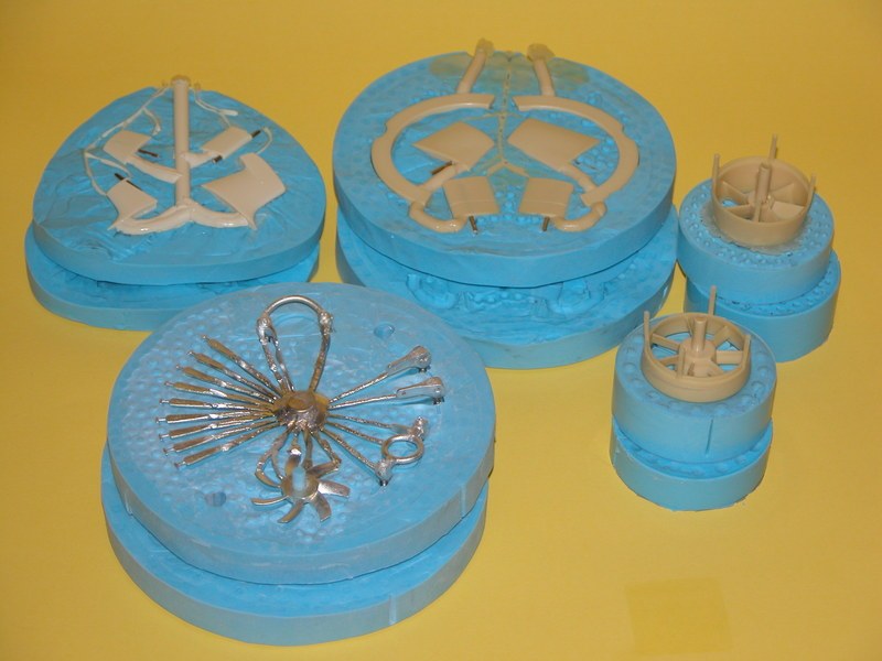
So once the moulds have been produced, you can start popping out parts. These vertical surfaces have turned out really well, I am happy with the results. Once these parts have come out the moulds they need little extra sanding and finishing..
I now have the moulds for the vertical stern planes, the Horizontal planes and the scoops. I now turn my attention to the sail once again and look at the mast heads and top of sail detail. I could have designed all these parts using Blender and then printing them out on the 3D printer from school. However I decided that I'd like to turn these up on the lathe. I don't get to spend as much time on the lathe as I'd like. I could easily just make parts on the lathe for the sake of just using it. I really like the benefits of 3D printing. However I really like the manual skills gained by using a lathe and also a milling machine. I don't have a mill, yet but am tossing up whether to buy one or not. I'd rather get one than a 3D printer. I know I would use it.
So taking the plan drawings of the various masts and looking at lots of photos I have got onto the lathe and started turning in my favourite material, brass. I have taken some 10 mm round brass bar and then bought this down to the required diameter for each part. I have also turned down a small diameter stem that would ideally slot into the top of the tube that I would use for the mast lengths. As can be seen numerous details have been added using styrene.
These masts include Radar masts, Radio antenna's and also the satellite navigation system which is large and bulky. It has it's own missile style door. As can be seen I have turned down the end stem to make a section that will slot into the right size tube when the time comes. I have added styrene where necessary. I have wrapped thin strip around the diameter of some of the parts as extra detail is required however to some extent I have had to guess as I can't seem to get hold of any really good up close detailed photos with most of the masts. I haven't started moulding these parts yet and will probably do this in the next couple of weeks.
The satellite navigation mast is the largest mast with the largest head of all. It has a round section that looks as though it clamps down over the top of the sat nav head. It look just like the round section that sits over the top of the missile in their bays. I have replicated with once again on the lathe. It is domed inside to give a concave appearance. There is also some detail in the form of flat plates welded around the circumference. These will be replicated by styrene. This mast has a door that looks like a missile door, just not as big. I have decided that I will also make a mould of this door as well as the head as an optional series of parts for the kit. I got some flat sheet of 2mm thick styrene sheet and marked out the profile for the sat nav door. This outline has already been scribed into the top of the sail so I just needed to trace around the scribed detail and then cut out the part. Once done and sanded I simply got out the heat gun and gently melted the edge on the lower side as the door has a bend in it towards the lower edge.
Once the door has been sanded and has the right curve, I then added the round drum, (for want of a better term). the blue section under the "Missile door". Once done It's glued to the styrene door.
Enough for now.
David H
Leave a comment:
-
Your still not canting the control surface masters during tool fabrication! No upper edge of a master should be parallel with the top of the tool!!!!! That's how you wind up with bubbles.
Don't make me come over there!
DavidLeave a comment:
-
Thanks David,
Fantastic knowledge as always...
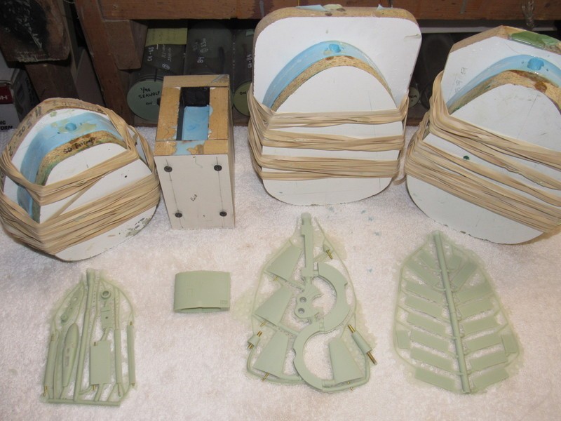
I have completed the horizontal stern plane moulds and punched out the first parts. They have turned out really well. There are a couple of spots at the edge of the end plates where there was a bubble occurring. I will cut a venting groove from these points to alleviate the bubble trap that has occurred there. As the parts come out some have rough part lines but nothing that can't be sanded back. The great thing is that there is no Swiss cheese.
Now all I needed to do was concentrate on the Vertical rear surfaces. Unlike the horizontal surfaces they are of course not symmetrical. The vertical upper fin is by far the biggest surface. Interesting as it is when on the surface mostly out of the water and thus ineffective. The lower fixed surface is by comparison quite small. One thing I have always wondered about is why they Delta series did not feature the lower rudder arrangement that is featured on the Oscar class. The 949 features a cool looking twin lower rudder arrangement that makes soo much sense for such large boats. The rear geometry of these two boats is almost the same so why did'nt they? It would certainly make this model more maneuverable. I am going to have to put a really decent sized cheater fin on the lower rudder, because its really tiny.
I had to put the end plates on the lower rudder surface. Then lots of coats of filler and grey primer to get the consistency just right. I have found that if there were gaps in between the end plates and the main surface then the filler wold usually give a nice smooth fill in between them. Then just the fine edge of the small file to smooth the corners. Then I had to scribe in the curious pattern of circles that are laid out over the lower rudder. After this then another light coat of primer being careful not to smooth over the detail of the small circles.
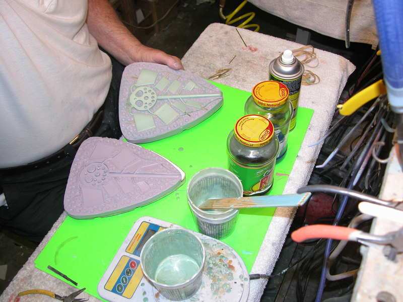
Once these were done and sanded down to 12oo grade paper I would then do the final checks on the top rudder and fin. A couple of fine coats of primer and then a really smooth finish. After this I would then once again take the particle board square that I use as a base and start laying out the arrangement of all the pieces. Once again I put down the pieces, work out the sprue and the vent placement and then drill the register holes around the rest of the board. Then I dremel out the area taken up by each piece and then fit those pieces so they are to some extent, 'sunken' into the board, half in and half out. This is probably the bit that takes the longest. Once this is done then work pout the four side pieces. Mark them out then drill and screw in the sides.
Once holes drilled, then paper clip wire laid down for the vents. Then balsa laid down for the sprues and eventually playdoh for the funnels at the top if the mould for the reservoir waiting area for resin in the pressure pot. All I need to add in this photo are the sides and the playdoh. Then a light spray of release agent. At the bottom i have put a strip of balsa just to act as a further barrier to resin seeping down.
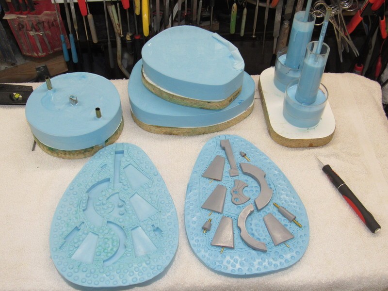
Here is once side of the mould. I moulded the first half and then turned it over. Cleaned it up pulled out the used playdoh and then rubbed lanolin into it to make a good barrier for the next layer of silicon.
Then replaced the parts and the balsa sprues, whilst filling the vents with some lanolin before screwing the sides back on and then pouring the next and final layer of silicon to complete the mould.
Enough for now,
Once again, Ideas and suggestions welcome.
David H
Leave a comment:
-
Avoid any edges to the tool cavities that would run horizontally. In the tool illustrated (the first one, with the stabilizers) the cavities should be canted so the leading edge at the root (the tip of the fillet) is high. And it is that tip where you provide just one vent channel. This way you don't catch any bubbles at the top of the tools cavities.
Like this:
DavidLeave a comment:
Leave a comment: