
I woke up yesterday intending to box up the 1.25 SD work and set it aside as I don�t have much time to prepare some subs for the JCC get-together this Sunday � our clubs first model boat outing of the year.
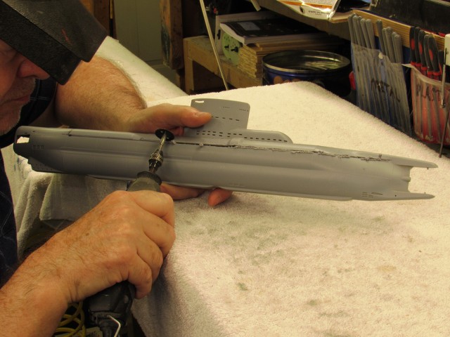
But, as you can see, I continued work on this aggravating yet seductive, 1.25� diameter, static-diving type SubDriver project. It�s been a total *****, but I love the challenge -- that love expressed as screams of rage and sound of tools bouncing off the shop walls.
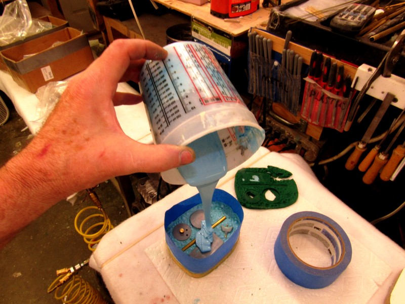
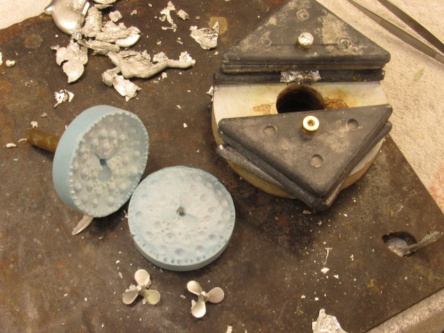
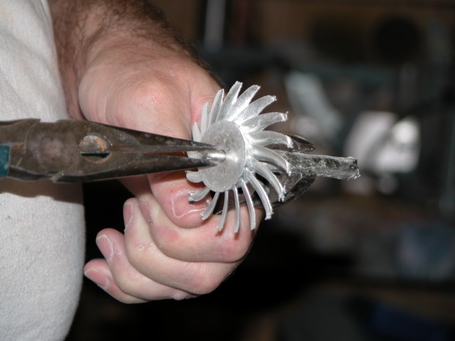
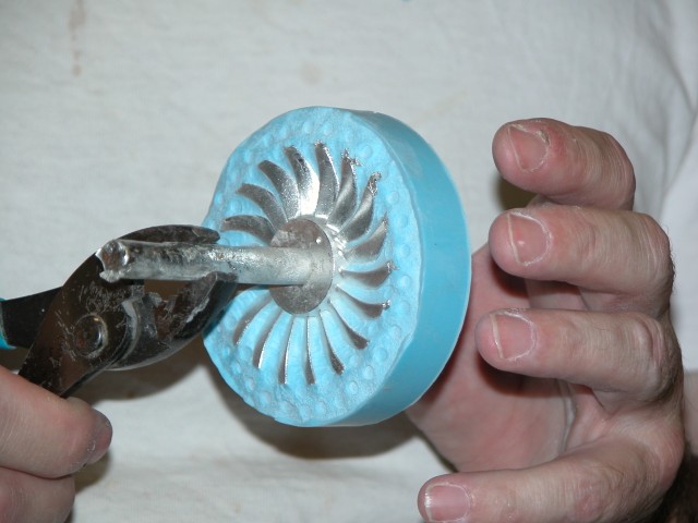
Last night I poured the second half of the rubber tool needed for the new parts previously discussed.
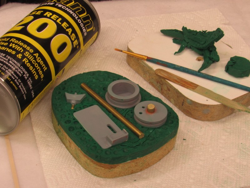
Here I�m embedding the masters in clay in preparation of making a pour to create the first half of the two-piece tool.
Pouring the second half of the tool last night. This work done just in time to catch an episode of Bob�s Burgers. Thank God! Then, off to bed. By morning time the rubber had cured and the tool opened up, the masters removed and put in safe storage, the vent and sprue channels cut out, and I was ready to cast the new parts for the little SD�s.
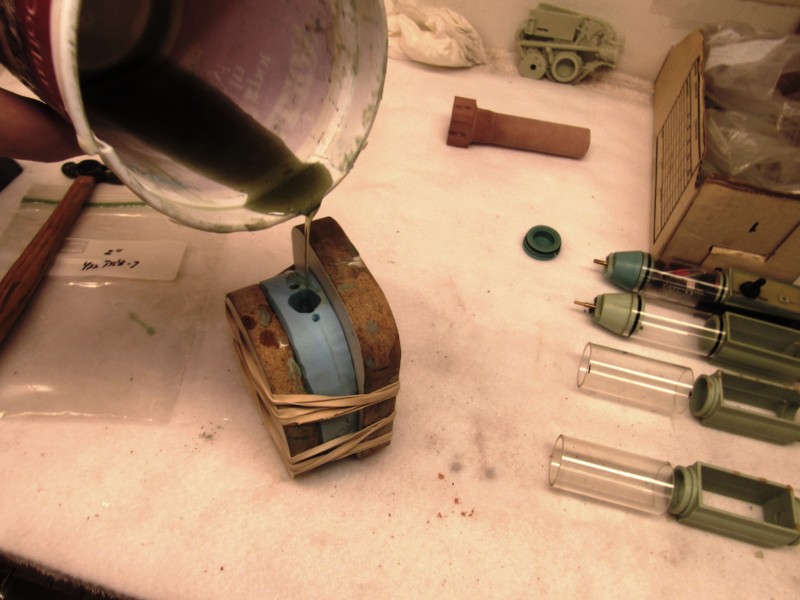
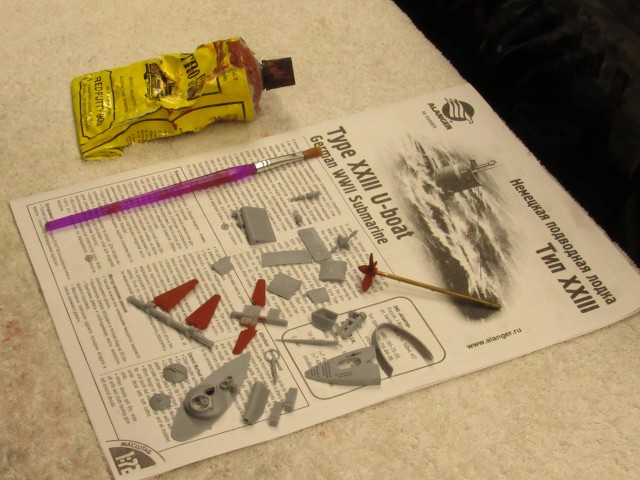
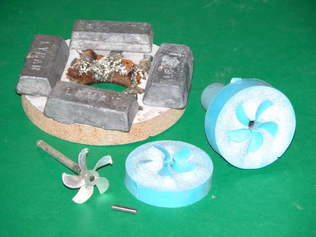
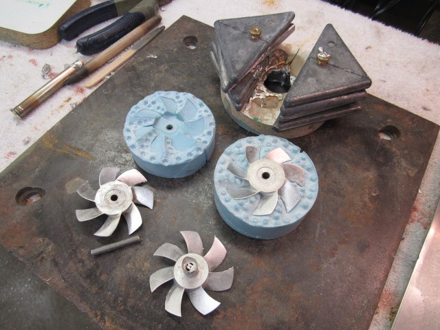
I cast my resin parts from the excellent Alumilite polyurethane resins, either the �fast� or the �slow� kind. Simple tools that fill quickly, like this one, permitted me to use the �fast� cure resin. By afternoon time I had three sets of parts in hand.
In background you can see two sets of parts up against the wall as I pour the just catalyzed resin into the tool for the third set.
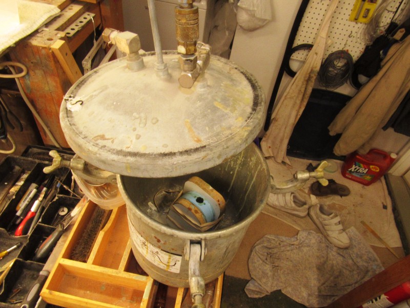
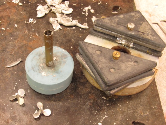
I pressurize the mix while it transitions from the liquid to solid state. This forces any bubbles in the mix to go back into the solution. The pressure (one atmosphere is enough) also forces any bubbles in tool voids to be crushed into the mix. The result is (most of the time) void free cast resin parts.
The pressure pot here is nothing more than a heavy-duty spray pressure pot pressed into resin work.
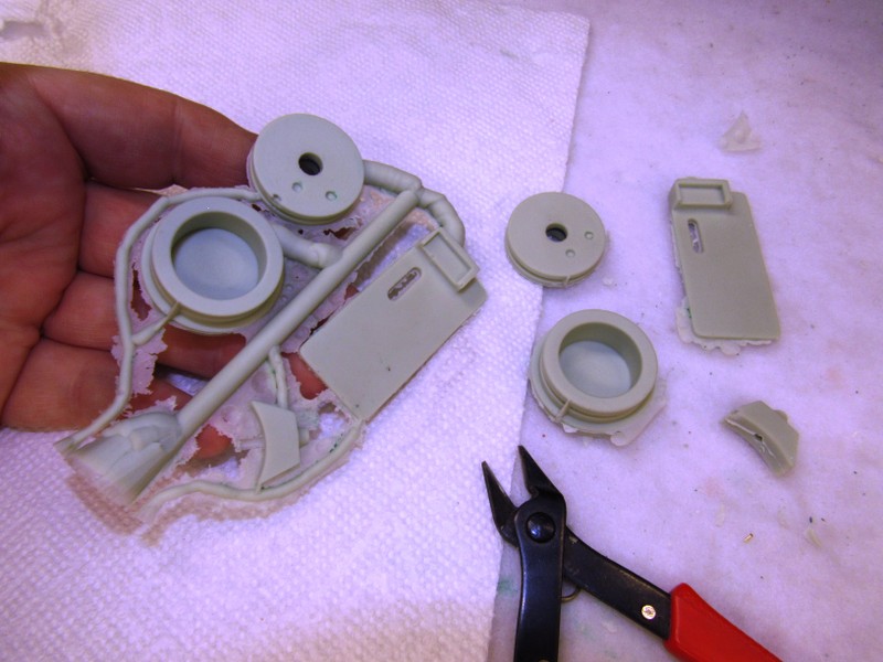
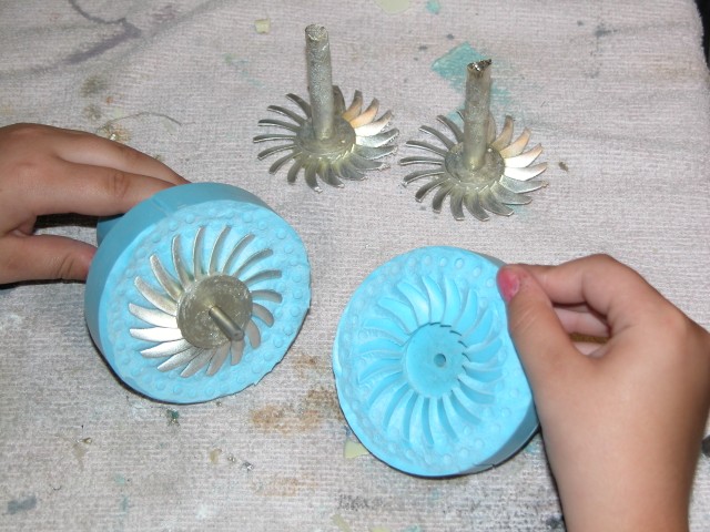
And the result: a set of parts pulled from the rubber tool. Note the arrangement of sprue and vent channels. The sprue and associated runners feed the resin into the cavities of the tool. The smaller vent channels in the tool permit the displaced air within the cavities to escape.
If you look closely at the center hole of the forward ballast bulkhead you can just make out the encapsulated rubber o-ring used to make a tight friction fit between it and the conduit.
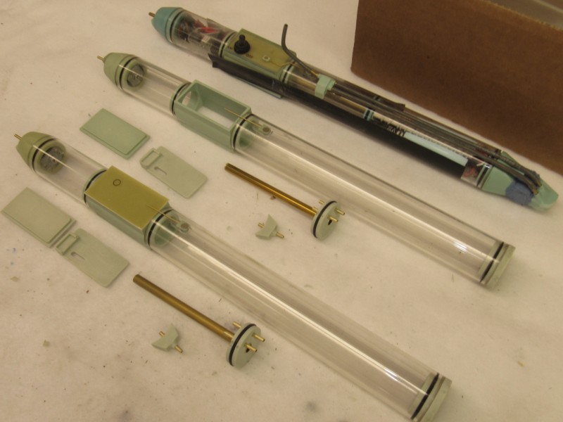
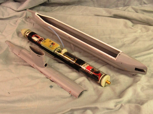
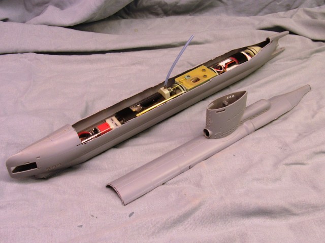
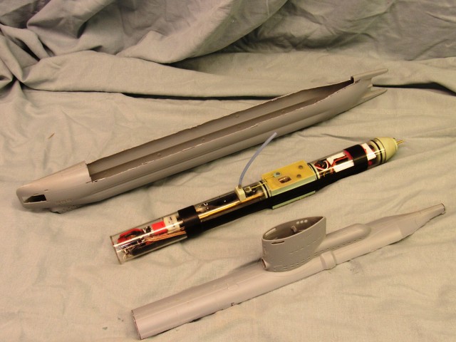
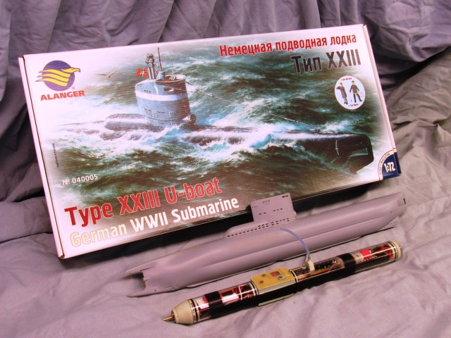
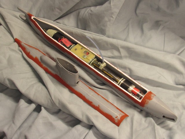
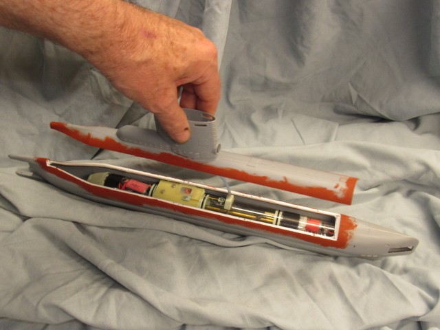
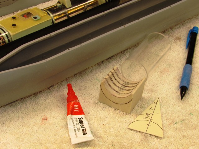
Two 1.25 SD�s with the new resin parts laid out for integration with the Lexan cylinder pieces.
In keeping with my practice of making as many system parts easily removable the o-ring fit of the forward ballast bulkhead to the conduit is a friction fit which can easily be parted if the forward Lexan cylinder length has to be pulled from the servo box.
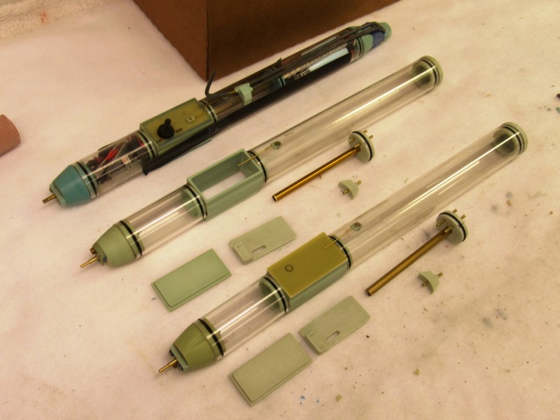
Not apparent here, but during the casting operation I incorporated a rubber o-ring where the conduit runs through the center of the forward ballast bulkhead. Once the length of the ballast tank has been determined, the conduit is cut to the appropriate length. The conduit, a length of brass tube will be provided the customer over-size. The after end of the conduit will eventually be CA�ed to the forward end of the servo box.
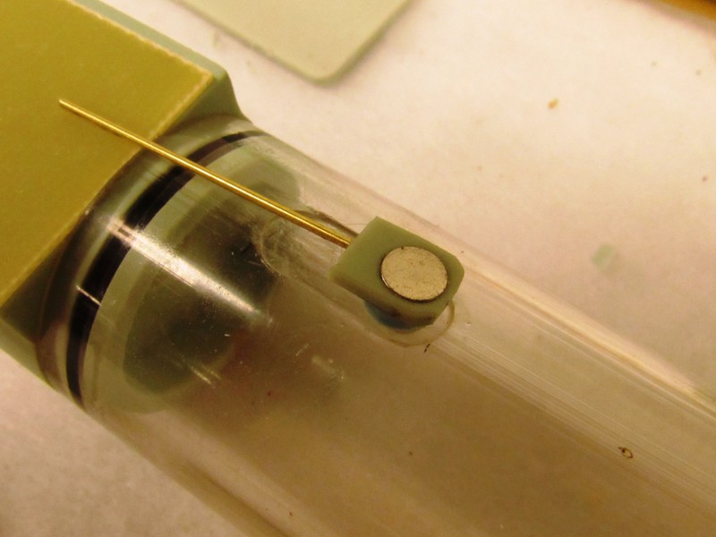
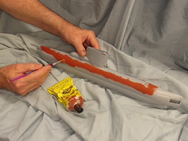
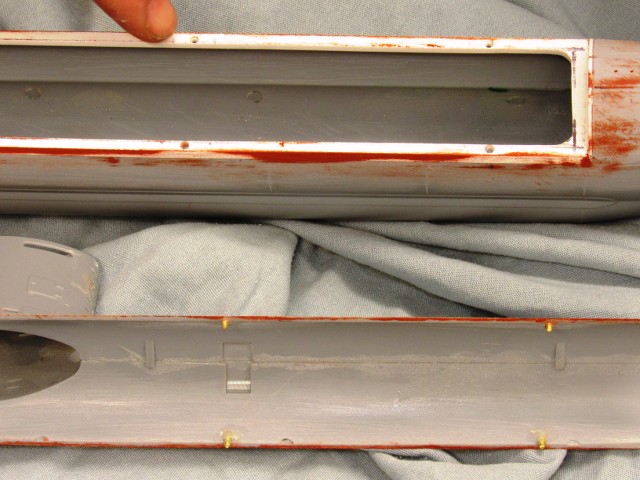
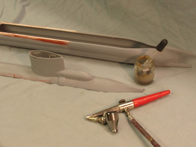
Vent valve open. The ballast sub-system servo is in the �vent� position. In that condition the LPB motor does not run and the ballast tank floods through the open bottom flood-drain hole. As air vents out of the tank it is displaced by water, diving the boat.
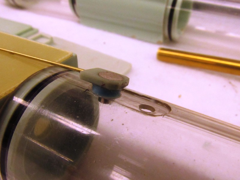
The flat channel upon which the rubber element slides is cut with an end-mill of a diameter slightly larger than the disc shaped rubber element.
And note the magnet atop the rubber element, and the magnet below within the ballast tank. These magnets work to press the rubber down tight against the channel insuring a gas tight seal. The magnet within the ballast tank is of a diameter slightly bigger than the vent hole, this prevents it from working its way out during valve operation. As the rubber element and its magnet slides atop, the lower magnet slides along with it within keeping a compressive force between rubber element and Lexan cylinder.
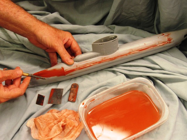
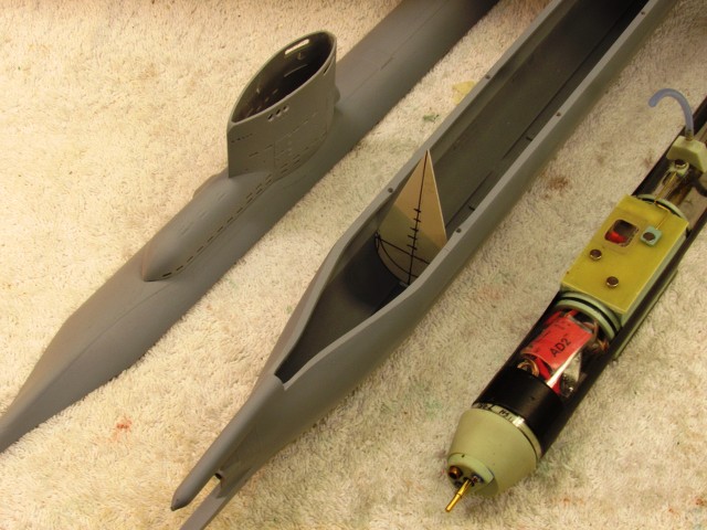
Vent valve closed. The ballast sub-system servo is at its �neutral� position � vent valve closed, LPB off. When the servo goes to the �blow� position the vent valve remains closed as you see here and the servo shuttle pushes the limit-switch to close the circuit to the LPB�s motor. The LPB takes a suction from atop the sail (presumably broached, but the pump can handle water without damage), compresses the air and discharges it into the ballast tank, blowing out the water through the open flood-drain hole in the bottom of the ballast tank.
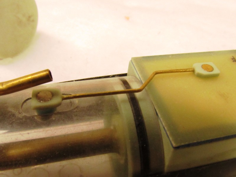
And here�s a look at a similar small SD slide-valve -- this one better illustrating how the ballast sub-system servo, through the magnet shuttle sitting atop the servo box, is linked to the rubber element of the vent valve mechanism.
The Z-bend in the pushrod permits fine adjustment of the rubber elements position over the vent hole.
David
But, as you can see, I continued work on this aggravating yet seductive, 1.25� diameter, static-diving type SubDriver project. It�s been a total *****, but I love the challenge -- that love expressed as screams of rage and sound of tools bouncing off the shop walls.
Last night I poured the second half of the rubber tool needed for the new parts previously discussed.
Here I�m embedding the masters in clay in preparation of making a pour to create the first half of the two-piece tool.
Pouring the second half of the tool last night. This work done just in time to catch an episode of Bob�s Burgers. Thank God! Then, off to bed. By morning time the rubber had cured and the tool opened up, the masters removed and put in safe storage, the vent and sprue channels cut out, and I was ready to cast the new parts for the little SD�s.
I cast my resin parts from the excellent Alumilite polyurethane resins, either the �fast� or the �slow� kind. Simple tools that fill quickly, like this one, permitted me to use the �fast� cure resin. By afternoon time I had three sets of parts in hand.
In background you can see two sets of parts up against the wall as I pour the just catalyzed resin into the tool for the third set.
I pressurize the mix while it transitions from the liquid to solid state. This forces any bubbles in the mix to go back into the solution. The pressure (one atmosphere is enough) also forces any bubbles in tool voids to be crushed into the mix. The result is (most of the time) void free cast resin parts.
The pressure pot here is nothing more than a heavy-duty spray pressure pot pressed into resin work.
And the result: a set of parts pulled from the rubber tool. Note the arrangement of sprue and vent channels. The sprue and associated runners feed the resin into the cavities of the tool. The smaller vent channels in the tool permit the displaced air within the cavities to escape.
If you look closely at the center hole of the forward ballast bulkhead you can just make out the encapsulated rubber o-ring used to make a tight friction fit between it and the conduit.
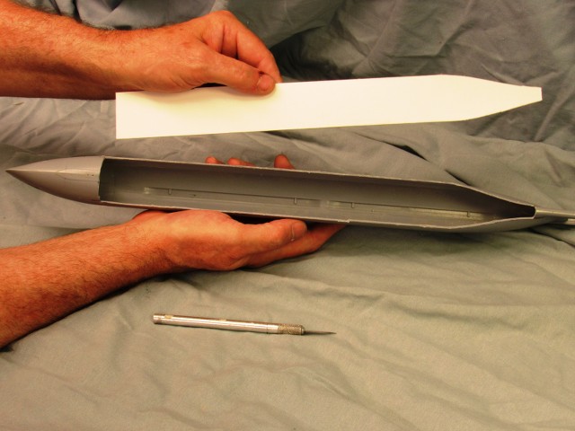
Two 1.25 SD�s with the new resin parts laid out for integration with the Lexan cylinder pieces.
In keeping with my practice of making as many system parts easily removable the o-ring fit of the forward ballast bulkhead to the conduit is a friction fit which can easily be parted if the forward Lexan cylinder length has to be pulled from the servo box.
Not apparent here, but during the casting operation I incorporated a rubber o-ring where the conduit runs through the center of the forward ballast bulkhead. Once the length of the ballast tank has been determined, the conduit is cut to the appropriate length. The conduit, a length of brass tube will be provided the customer over-size. The after end of the conduit will eventually be CA�ed to the forward end of the servo box.
Vent valve open. The ballast sub-system servo is in the �vent� position. In that condition the LPB motor does not run and the ballast tank floods through the open bottom flood-drain hole. As air vents out of the tank it is displaced by water, diving the boat.
The flat channel upon which the rubber element slides is cut with an end-mill of a diameter slightly larger than the disc shaped rubber element.
And note the magnet atop the rubber element, and the magnet below within the ballast tank. These magnets work to press the rubber down tight against the channel insuring a gas tight seal. The magnet within the ballast tank is of a diameter slightly bigger than the vent hole, this prevents it from working its way out during valve operation. As the rubber element and its magnet slides atop, the lower magnet slides along with it within keeping a compressive force between rubber element and Lexan cylinder.
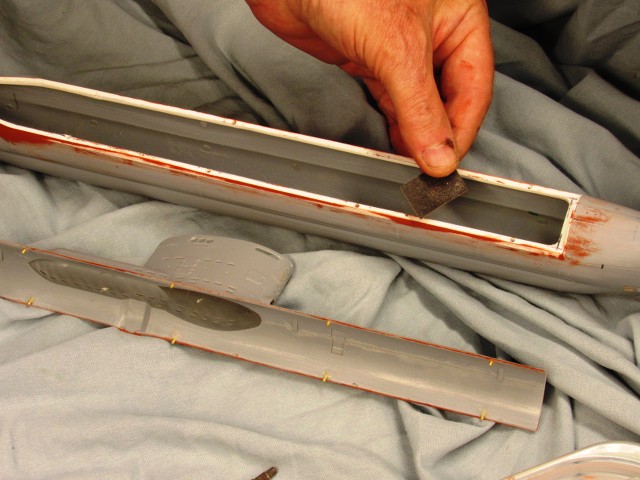
Vent valve closed. The ballast sub-system servo is at its �neutral� position � vent valve closed, LPB off. When the servo goes to the �blow� position the vent valve remains closed as you see here and the servo shuttle pushes the limit-switch to close the circuit to the LPB�s motor. The LPB takes a suction from atop the sail (presumably broached, but the pump can handle water without damage), compresses the air and discharges it into the ballast tank, blowing out the water through the open flood-drain hole in the bottom of the ballast tank.
And here�s a look at a similar small SD slide-valve -- this one better illustrating how the ballast sub-system servo, through the magnet shuttle sitting atop the servo box, is linked to the rubber element of the vent valve mechanism.
The Z-bend in the pushrod permits fine adjustment of the rubber elements position over the vent hole.
David


Comment