-
Who is John Galt? -
... a computer once beat me at chess, but it was no match for me with kickboxing!!Comment
-
Major status report going together tonight, with pictures. I've made some radical changes as to plumbing and internal layout. Easy to assemble and maintain. Film at Eleven!
DavidWho is John Galt?Comment
-
I�m finalizing the design of the 1.25� static diving type SD. It�s been a long and frustrating road. The work started over ten years ago. There have been design changes, brought on by new products needed to populate the system.
A quick summation of what has happened to alter the design of this static diving type 1.25 SD over time:
1. Devices aboard the SD have drastically reduced in size and improved in function over time
2. Because of the smaller sized LPB I came up with a much improved routing of the snort plumbing
3. A more practical arrangement of the devices to limit wire-runs
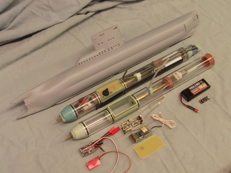
Below is pictured the original proof-of-concept SD, just below the 1/72 Type-23 hull. As you can see it has been populated with all the devices, and has been tested and works fine. However, that version of the static diving 1.25 SD is a ***** to wire, and some of the devices take up a lot of real-estate.
The unpopulated SD below -- it�s devices arrayed under it � is built to take advantage of these new developments. The most significant improvement is a much reduced in size low pressure blower (LPB) that permits internal running of the induction and discharge hoses. Also, much smaller, linear type servos free up room that now permits placement of the receiver under them, within the cast resin servo box. Substitution of the toggle mission switch with a tiny, magnetically actuated mission switch makes the wiring within the servo box a lot easier. And, finally elimination of the Lipo-Guard/Battery Link Monitor has simplified wiring and frees even more space within the cylinder.
You�ll notice that this new arrangement results in nearly a 25% increase in ballast tank size for a given SD cylinder length.
[IMG]file:///C:/Users/David/AppData/Local/Temp/msohtmlclip1/01/clip_image002.jpg[/IMG]
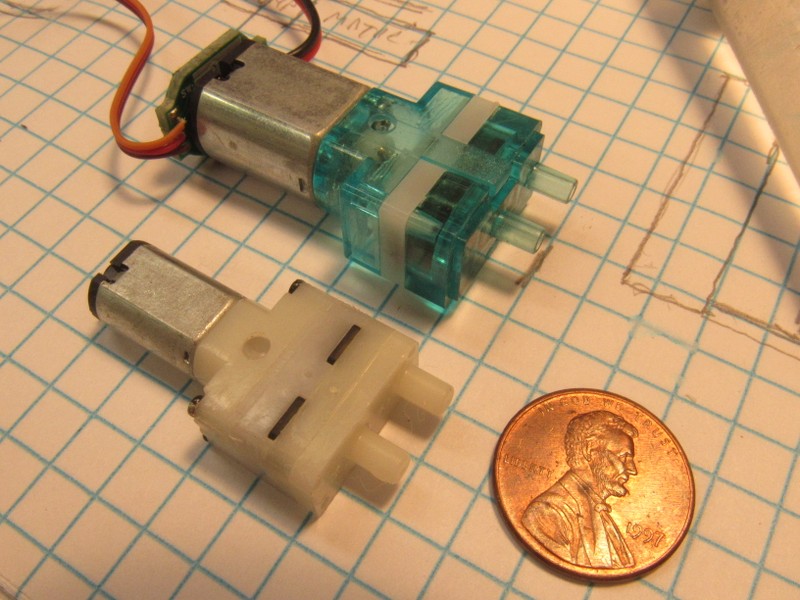
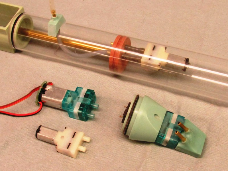
The big game-changer is the new (new to me, anyway), much smaller two-stage, diaphragm air pump. Unlike the stock LPB, this smaller pump fits easily within the SD. Also, as this 3-volt unit draws much less current, I�m able to eliminate the dedicated LPB motor-controller. Now the LPB pump is run through a simple servo controlled limit-switch.
[IMG]file:///C:/Users/David/AppData/Local/Temp/msohtmlclip1/01/clip_image004.jpg[/IMG]
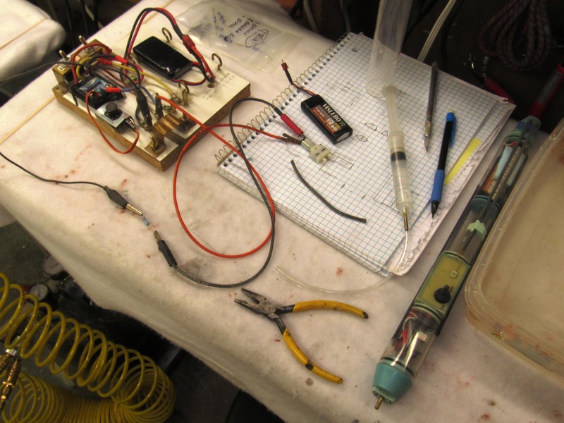
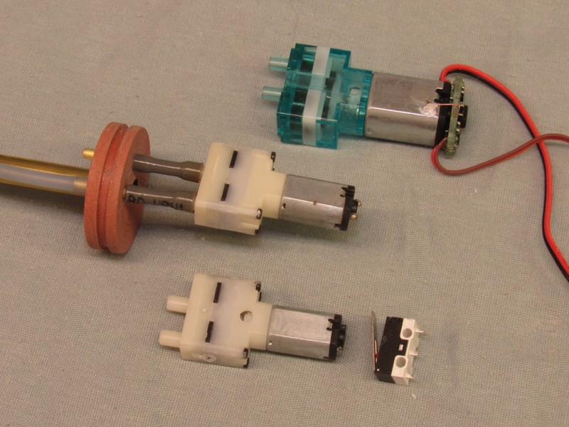
Of course I first conducted some testing to insure that water ingested into the pump would not migrate anywhere else. The same testing protocol used for the big original LPB was employed to validate the smaller unit.
What I�m determining the value of the voltage dropping resistor needed to get this little motor down from the 7-volt line voltage to the 3-volts. Ohm�s law is your friend, but it never hurts to breadboard the circuit to see if it does the job.
The syringe is used to send pressurized water first into the pumps inlet port, then the outlet port � if there is any leak between the pump body and pump foundation, it will be revealed through the weep-holes drilled into the pump foundation.
Ten of these little LPB�s checked, not one leaked. A much improved batting average than the bigger LPB, which exhibits a failure rate of 20%.
[IMG]file:///C:/Users/David/AppData/Local/Temp/msohtmlclip1/01/clip_image006.jpg[/IMG]
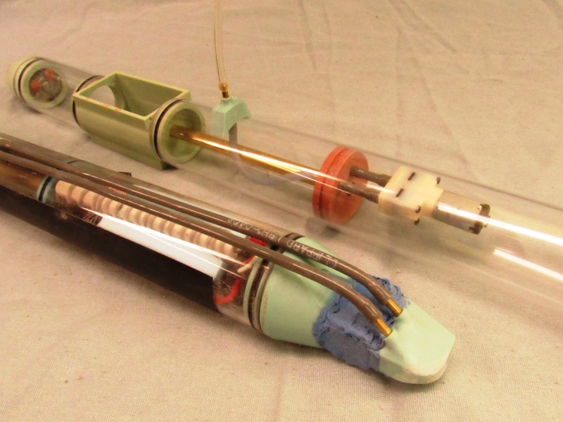
This is the big deal: Where before I was compelled to build a dedicated forward bulkhead to house the big LPB and run its plumbing (induction and discharge hoses) external of the cylinder, now � with the smaller LPB � the plumbing is reduced to a short internal run of induction and discharge hose between pump and ballast tank forward bulkhead.
Note that the induction hose continues within the ballast tank, up into a manifold where the induction hose stands vertically where it will be at the topmost portion of the model submarines sail. We�ll be able to empty the ballast tank the moment the sail broaches the surface.
The brass tube running through the ballast tank is a conduit between forward dry space and the servo box. Through this will pass the power cable and wires between LPB motor and its limit-switch.
[IMG]file:///C:/Users/David/AppData/Local/Temp/msohtmlclip1/01/clip_image008.jpg[/IMG]
Though the LPB is now internally mounted, there is still room under it to place the after end of the battery. For a length of 1.25�cylinder that can comfortably fit the 1/72 Type-23 hull, the new design increases the length of the ballast tank over that of the original design.
Note how the simplified plumbing works: Air is drawn in from the broached sail down the vertical length of induction hose; through the manifold atop the ballast tank where another length of hose makes up to a nipple that directs the air forward through the forward ballast bulkhead; and then through another short length of induction hose into the suction side of the LPB. Compressed air is then sent aft through the short length of discharge hose; through the forward ballast bulkhead nipple; and into the ballast tank, blowing out the water through the open flood-drain hole at the bottom of the ballast tank.
(The lengths of Acrylic cylinder here are simple place holders and will be replaced with Lexan cylinder lengths � with complete ballast tank machining and function � once all the details are worked out).
[IMG]file:///C:/Users/David/AppData/Local/Temp/msohtmlclip1/01/clip_image010.jpg[/IMG]
The low-current drawing smaller LPB motor can now be controlled through a simple (and cheap) mechanical switch; a limit-switch that is actuated at the extreme � blow� position of the ballast sub-system servo. This arrangement reduces the need to route the three-wire lead between an (expensive) motor pump controller and receiver.
In this arrangement I need only run power from the limit-switch to the LPB motor.
Note the tan color of the internal forward ballast bulkhead. It�s a turned master being test fitted here. It will be used (with the other new masters) to create rubber tooling from which resin parts will be produced.
[IMG]file:///C:/Users/David/AppData/Local/Temp/msohtmlclip1/01/clip_image012.jpg[/IMG]
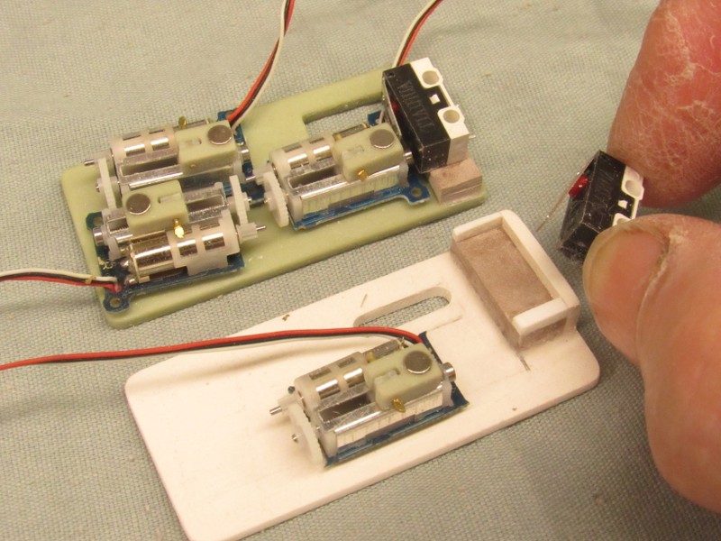
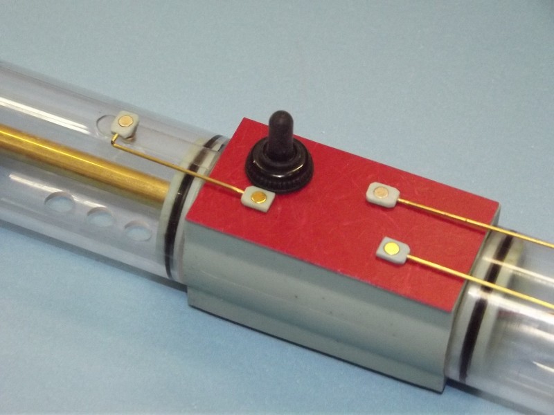
The LPB motor limit-switch is closed when the ballast sub-system servo magnet shuttle travels forward to the extreme �blow� position. The switch is open in the �vent� and �neutral� positions.
[IMG]file:///C:/Users/David/AppData/Local/Temp/msohtmlclip1/01/clip_image014.jpg[/IMG]

The white platform, with a dedicated foundation for the LPB limit-switch, is a master that will be used to eventually produce parts like the earlier version seen above slapped together to prove out the concept of using a limit-switch to control the LPB.
[IMG]file:///C:/Users/David/AppData/Local/Temp/msohtmlclip1/01/clip_image016.jpg[/IMG]
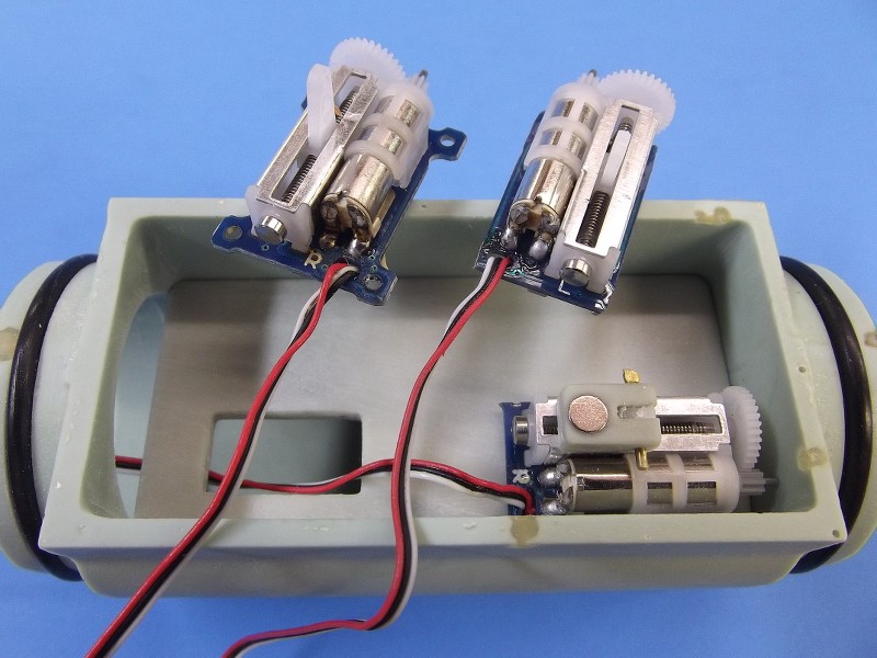
The three servos needed to control the rudder, stern planes and ballast sub-system are mounted on a platform that sits within the cast resin �servo box�. The tops of the servo magnets -- each set within a shuttle that makes up to the linearly running servo bell-crank -- are even with the bottom of the G-10 cover.
[IMG]file:///C:/Users/David/AppData/Local/Temp/msohtmlclip1/01/clip_image018.jpg[/IMG]
The coupling between external push rods and servos is magnetic. An uncomplicated watertight linkage between servo and item being moved by that servo, no seals involved.
[IMG]file:///C:/Users/David/AppData/Local/Temp/msohtmlclip1/01/clip_image020.jpg[/IMG]
So, William: that�s where we�re at as of last night. Today I make the new tools. Tomorrow I produce the parts and, in short order, assemble two, Type-23 SD�s: one for you, one for me.
David
Who is John Galt?Comment
-
... a computer once beat me at chess, but it was no match for me with kickboxing!!Comment
-
Thanks. We're in the short-strokes now. Tool for the new resin parts is done and I cast up a few sets this morning. Then, next week (I have an event to get ready for) I'll build up my unit, test it, finalize the design and assembly methodology, and finally get your SD done and off to Bob for shipment.
DavidWho is John Galt?Comment
-
David, is this a SAS type unit? You are building the vacuum in the tube, how is the air replenished?
This is a really cool design and kudos to you.If you can cut, drill, saw, hit things and swear a lot, you're well on the way to building a working model sub.Comment
-
Hey, Tom (unacknowledged master of stupidly small r/c submarines -- ask him to show off his little ALUMANAUT!)
No, not SAS. Snort.
It's an open-loop between ballast tank and atmosphere. No blow air is scavenged from the dry spaces. If the model can't broach the sail, it ain't coming up!
No room in that tiny cylinder to fit a proper float safety-valve. These are pool-toys anyway. Only an idiot would operate one of these things in open water.
Duh!
DavidWho is John Galt?Comment
-
humbled, in my proper place, and shrinking into my corner......repeating the phrase "You're the man"If you can cut, drill, saw, hit things and swear a lot, you're well on the way to building a working model sub.Comment
-
It uses a piston and taught me SMALL is not always the best!
If you can cut, drill, saw, hit things and swear a lot, you're well on the way to building a working model sub.Comment


Comment