-
The last post about the build was October 2016. Well, I finished the boat but stopped there. No trimming, no run....so late 2020 I decided to finally get it wet. And so I did. Started trimming a week ago. Unfortunately it has a leak and it took me a while to identify where it is. Seems like te bajonet catch has a bit large tolerances. So I will degrease it and then put some scotch tape under the O-ring. Should fix the problem. And then back into the tub...
Last edited by DrSchmidt; 11-18-2020, 09:05 AM. -
I'm still waiting to see it with one of your beautiful paint jobs....Originally posted by He Who Shall Not Be NamedLeave a comment:
-
I think I still have three hulls and PE parts for them. The resin details could be produced as well. But in the moment I'm mooving and therefore have any time for building stuff.....later this year maybe.Leave a comment:
-
I hate to comment on a 4 year old post, but what a fantastic build. Any shots of her in the water? I wish you had produced more. I’m just getting to a lot of the builds here, but when I look at the dates it’s just amazing that many are either sold or stored somewhere. Anyway, great thread.
CaseyLeave a comment:
-
WOW! You've proven that you really know how to impress this group!Leave a comment:
-
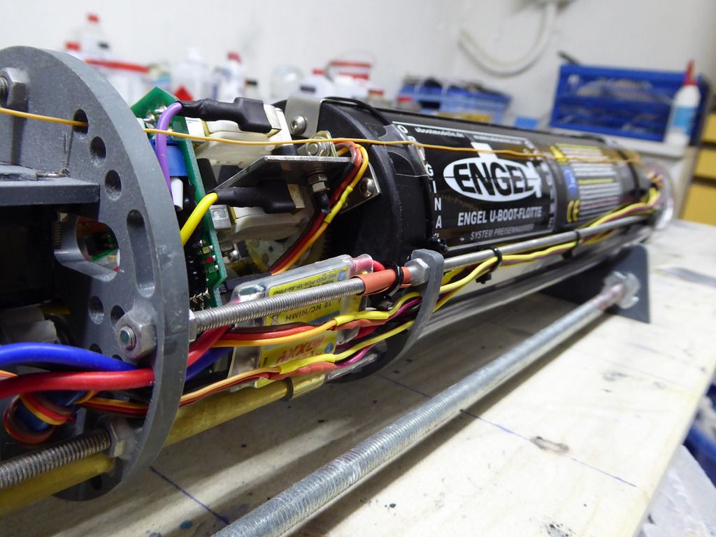
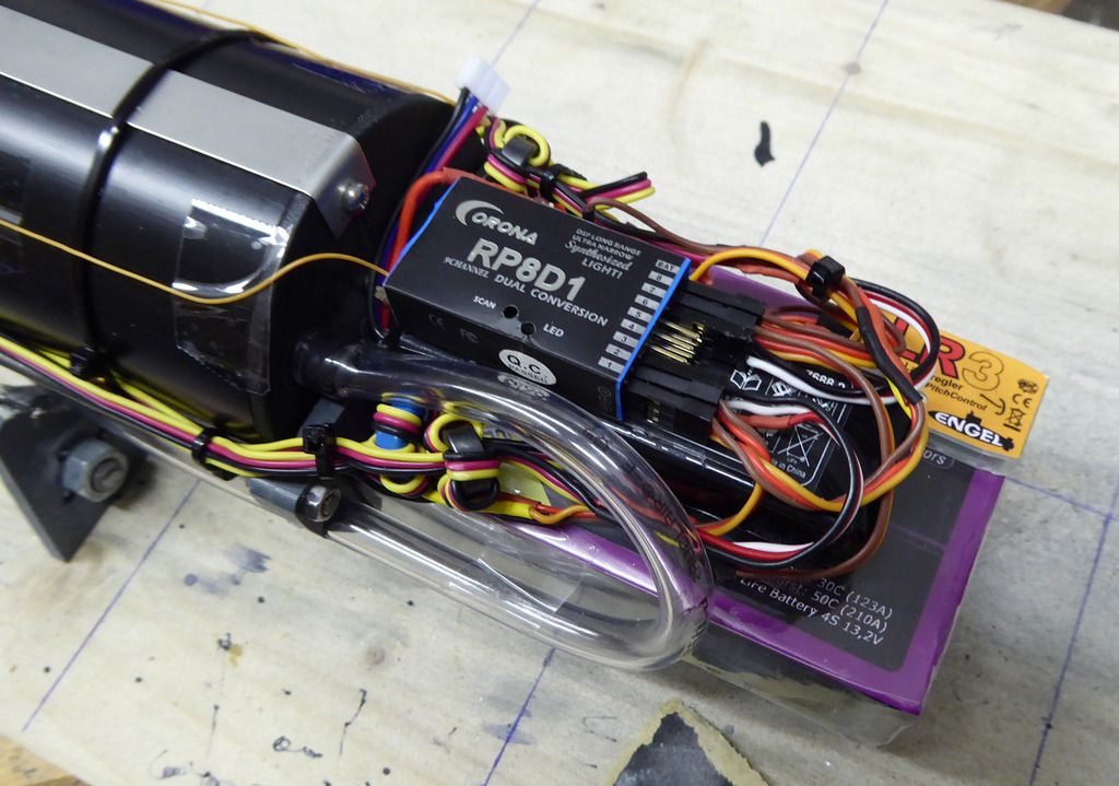
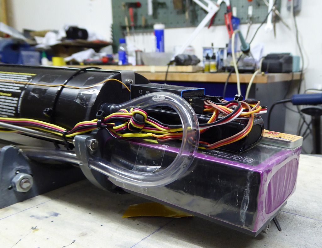
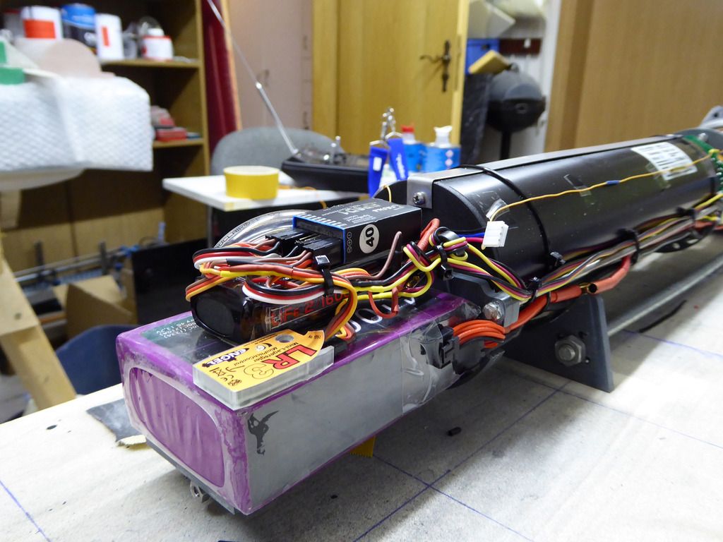
All components are installed and wired. The two Roxxy speed controllers sit left and right of the tank controller. At the front sits the 4100 mAh LiFePo battery. On top of it sits the LiFePo receiver battery and above all the Corona receiver. Next to it there still is enough space for the Engel auto-leveler. Look quite busy but actually it�s quite tidy and well accessible:
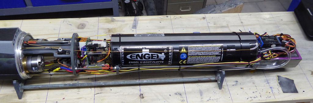
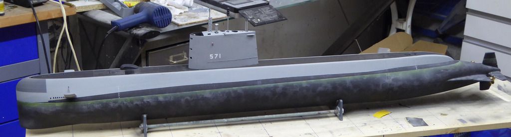
And because it looks so nice, again the complete boat:
Leave a comment:
-
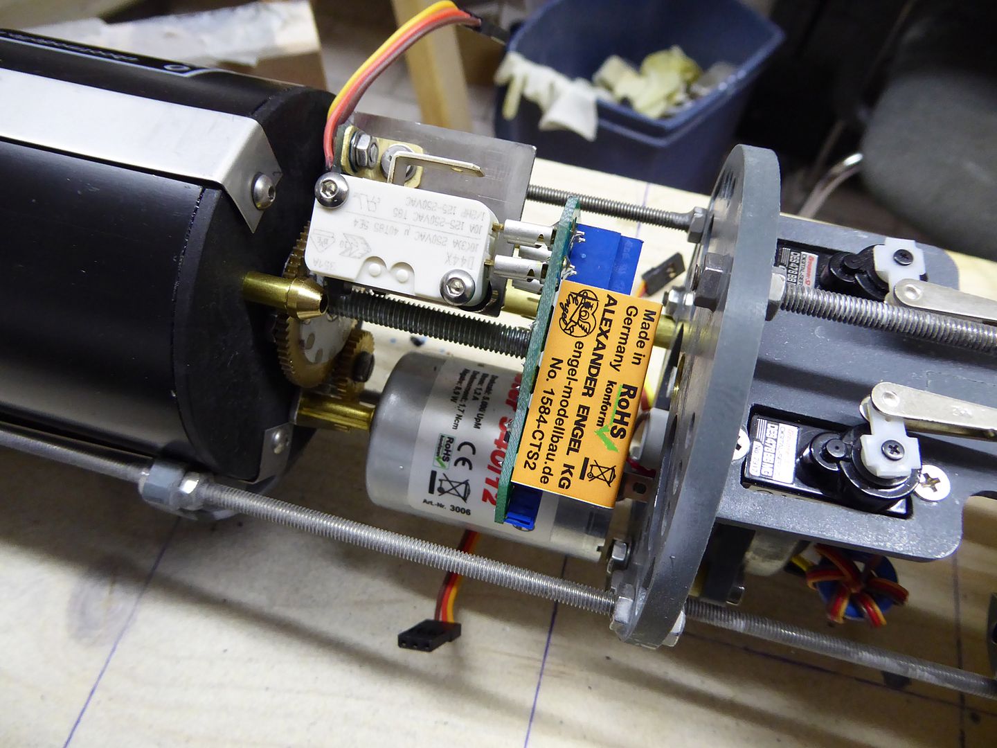
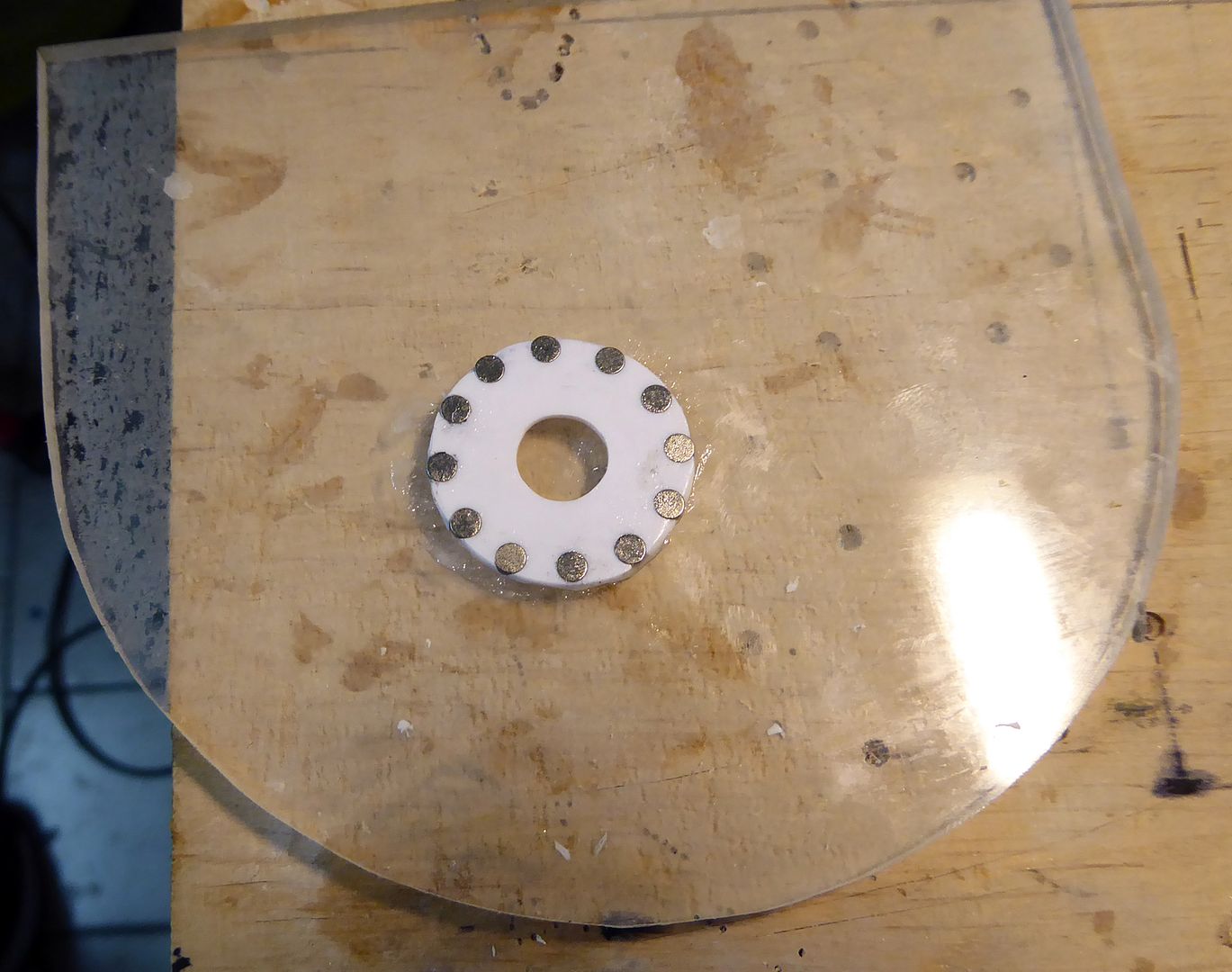
After the glue has cured clean the magnet disk from glue residues, cut it into two pieces and glue it onto the main gear of the piston tank. Then put the control unit onto the micro switches:
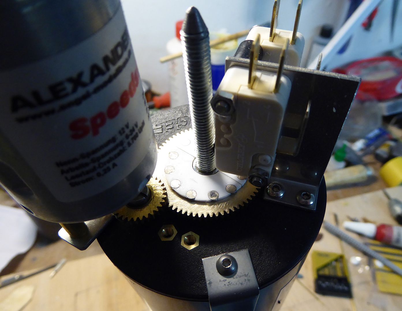
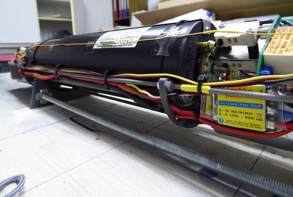
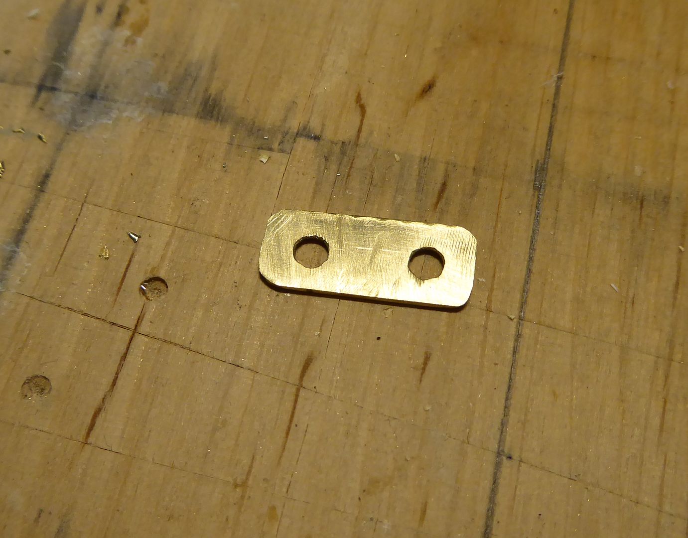
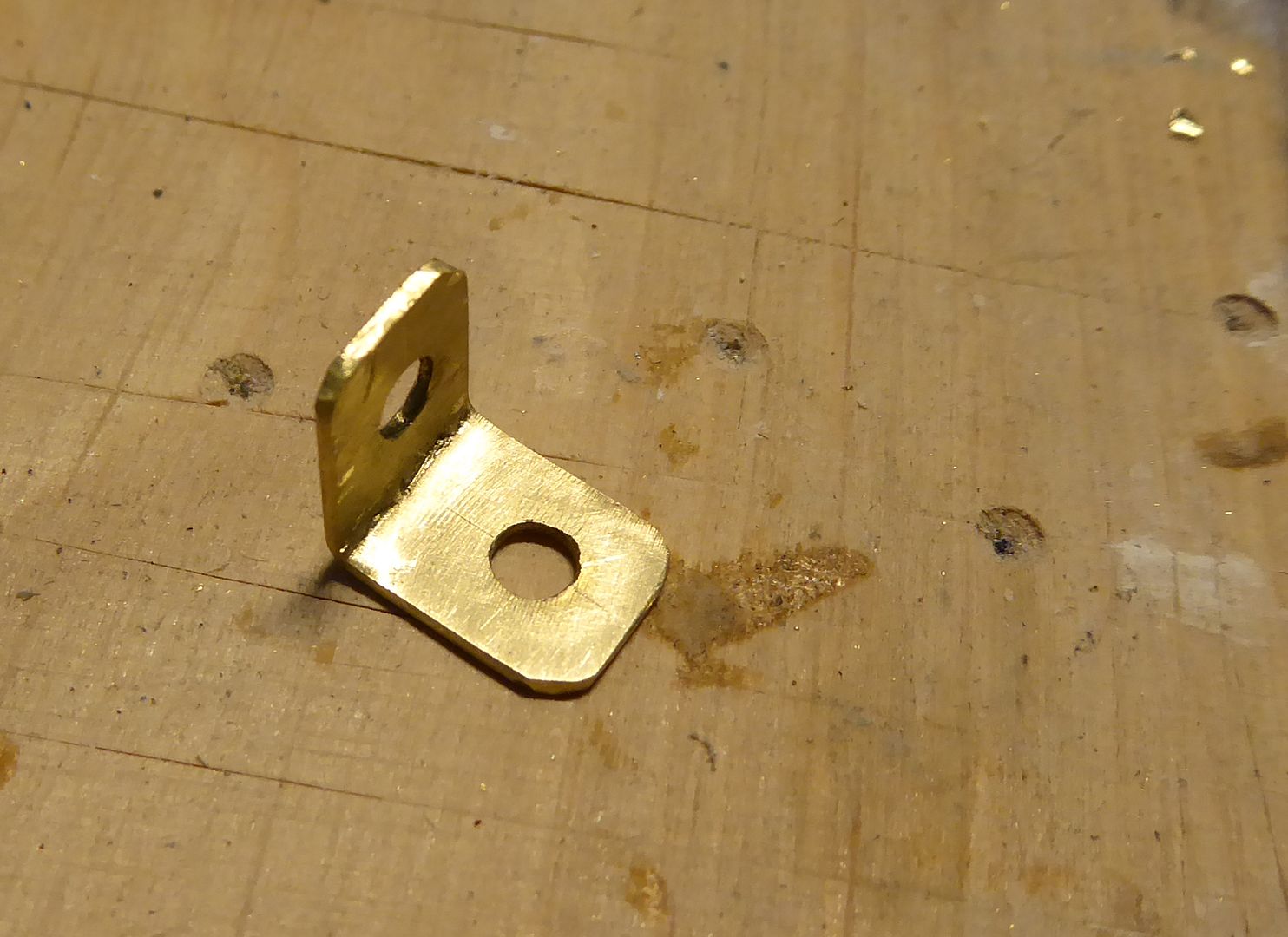
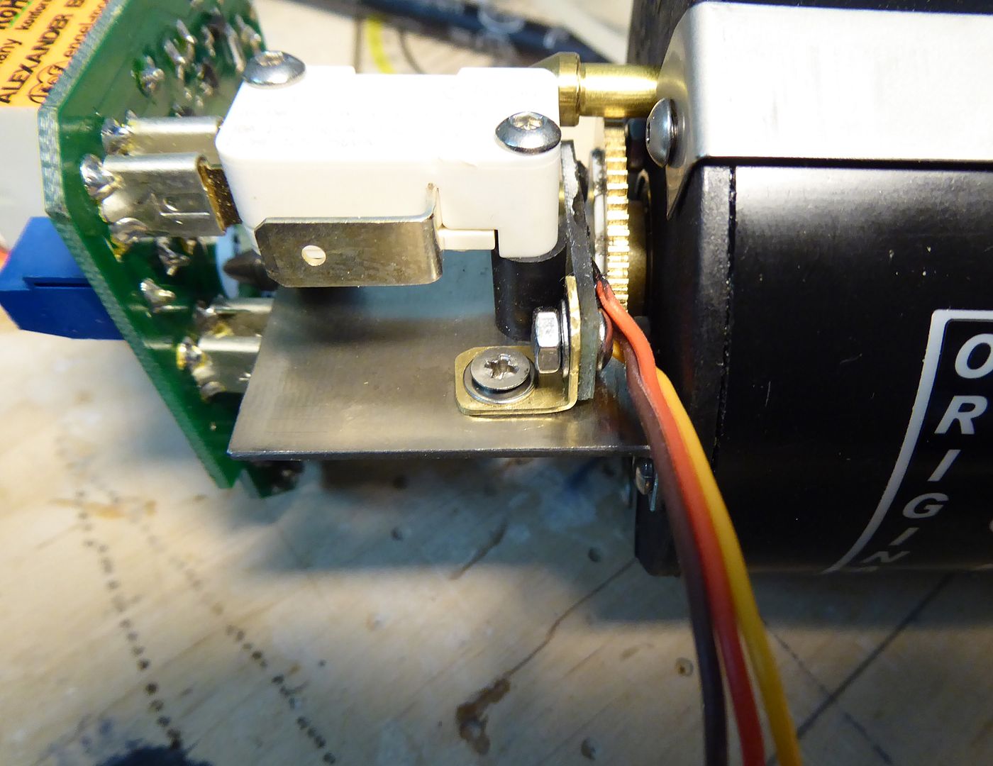
The 540-version of the piston tank has no fix point for the Hall sensor. Therefore one fabricates a L-bracket out of 1 mm brass sheet material:
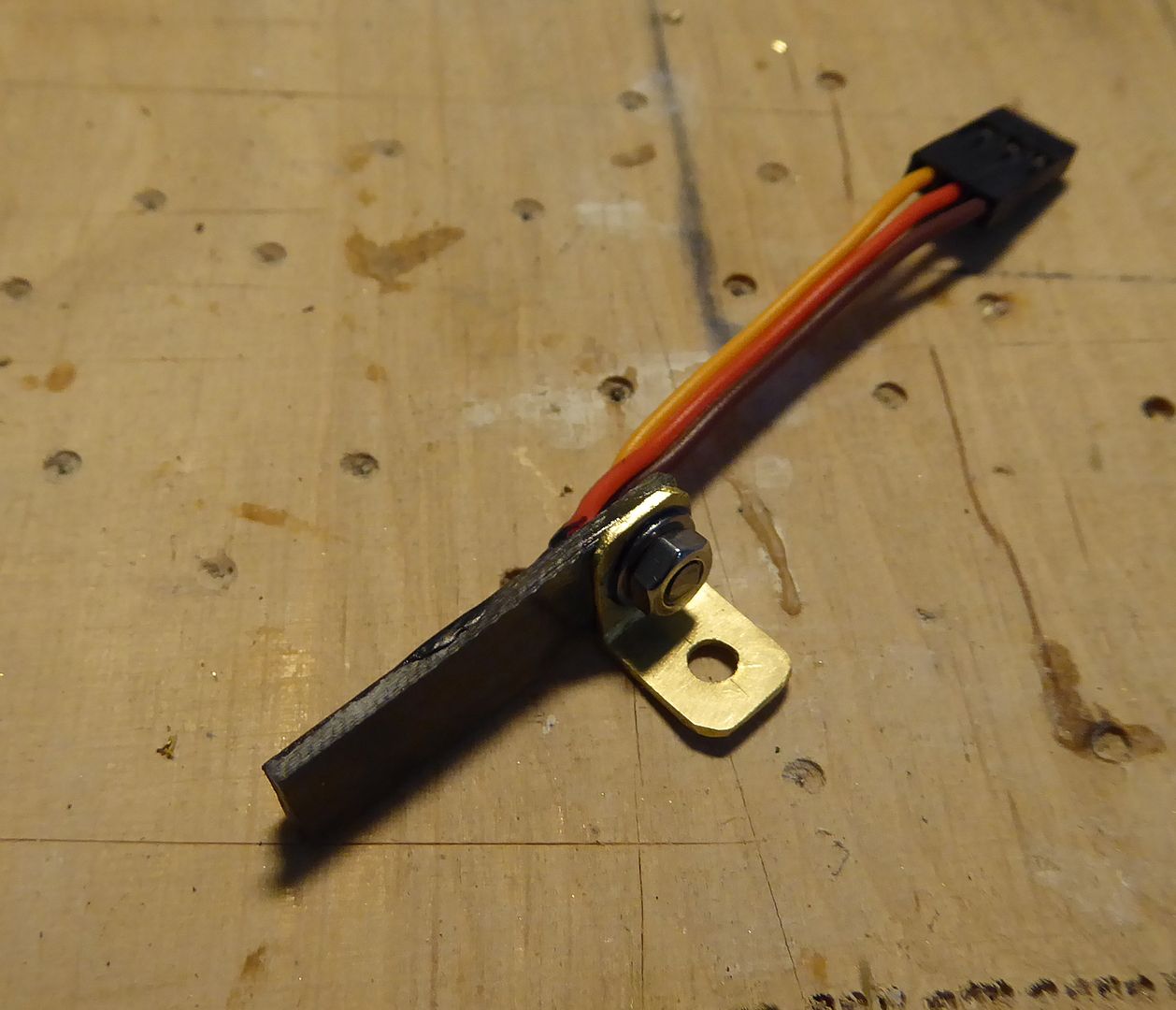
The Hall sensor is screwed into place, a 3mm diameter hole is drilled into the micro-switch board of the piston tank and then the Hall sensor is installed so that the magnets pass closely to the sensor head when the gear turns:
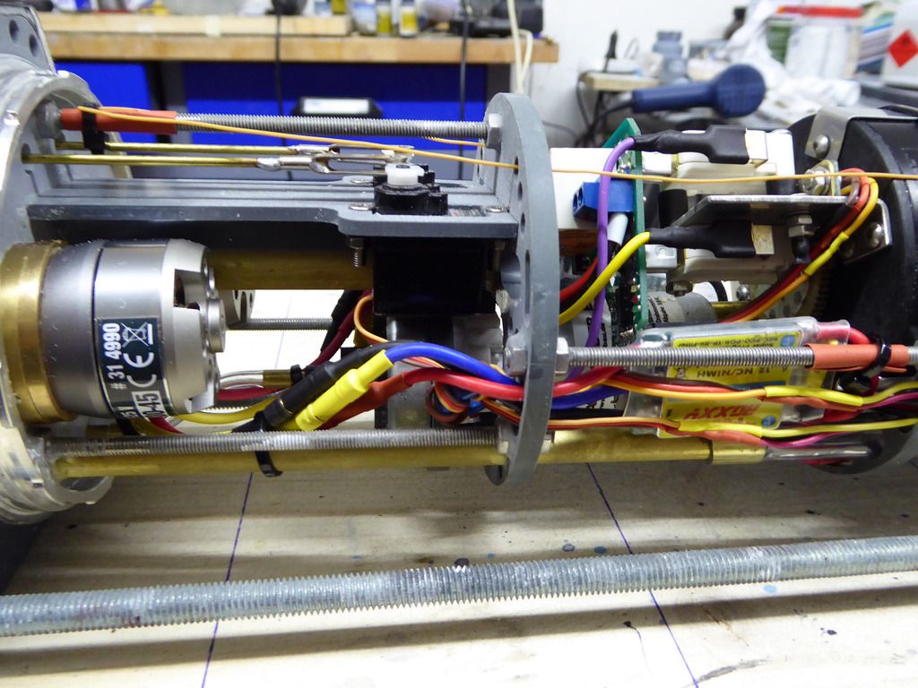
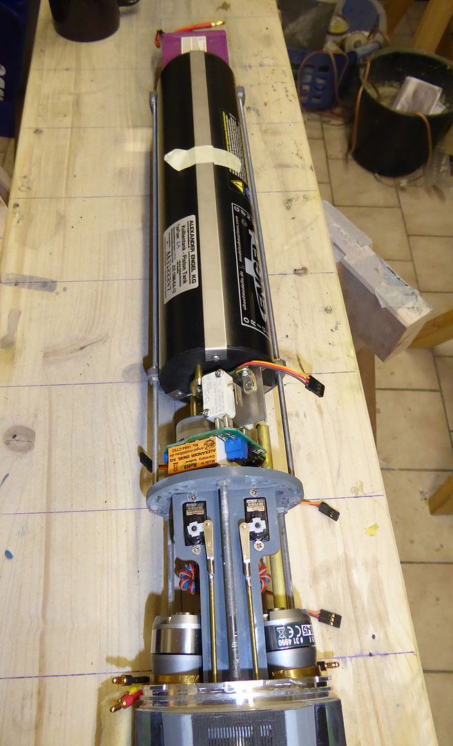
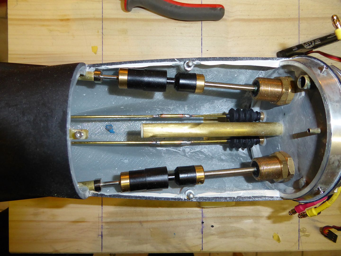
Test fit everything in the inner structure:
Leave a comment:
-
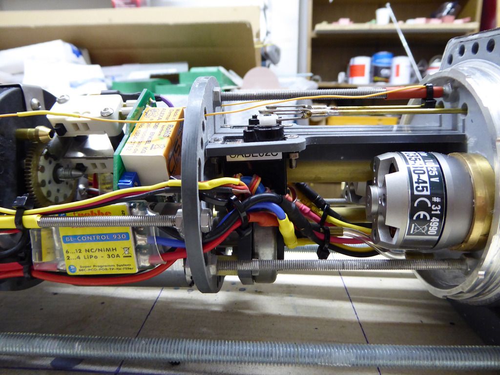
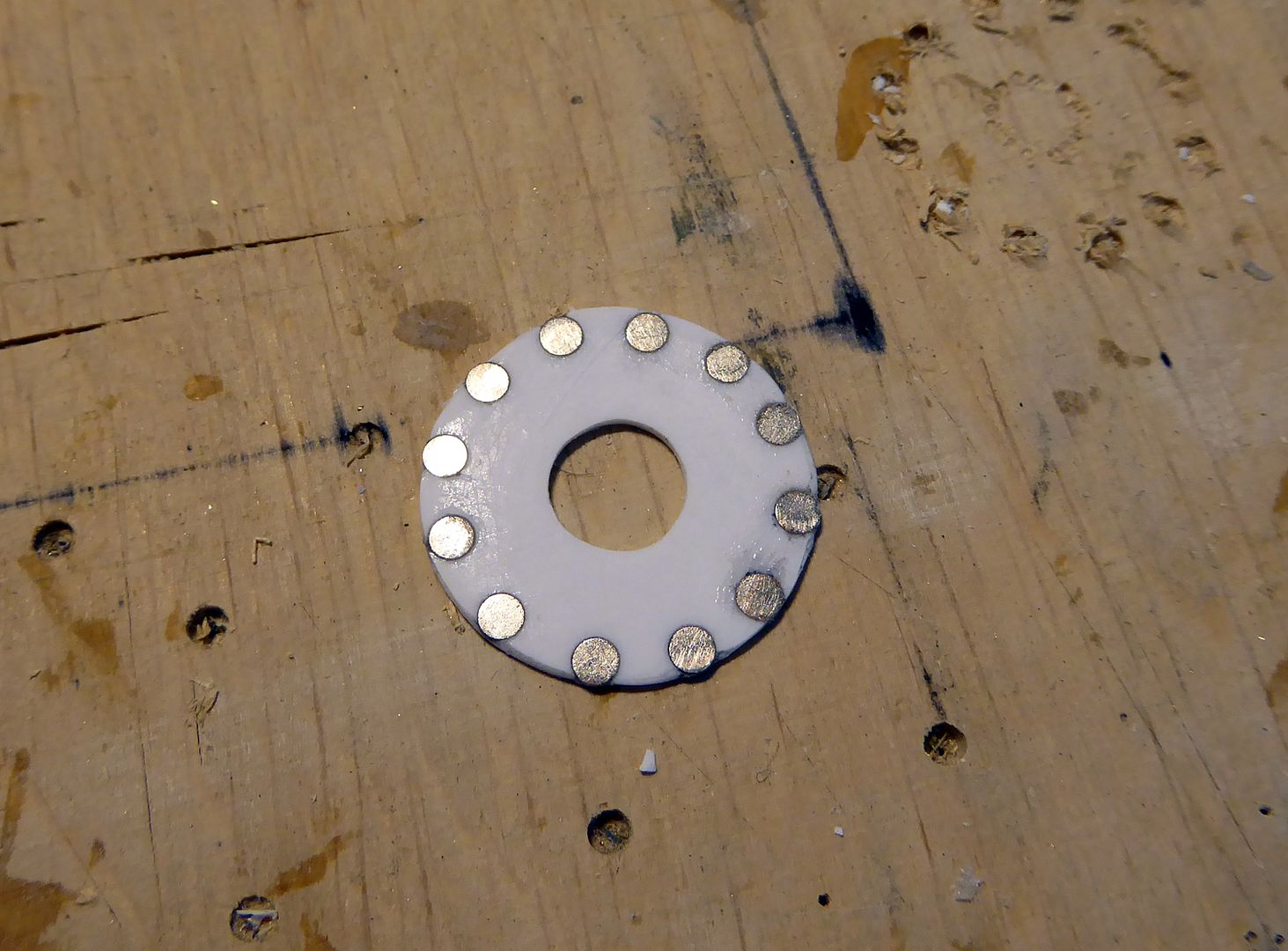
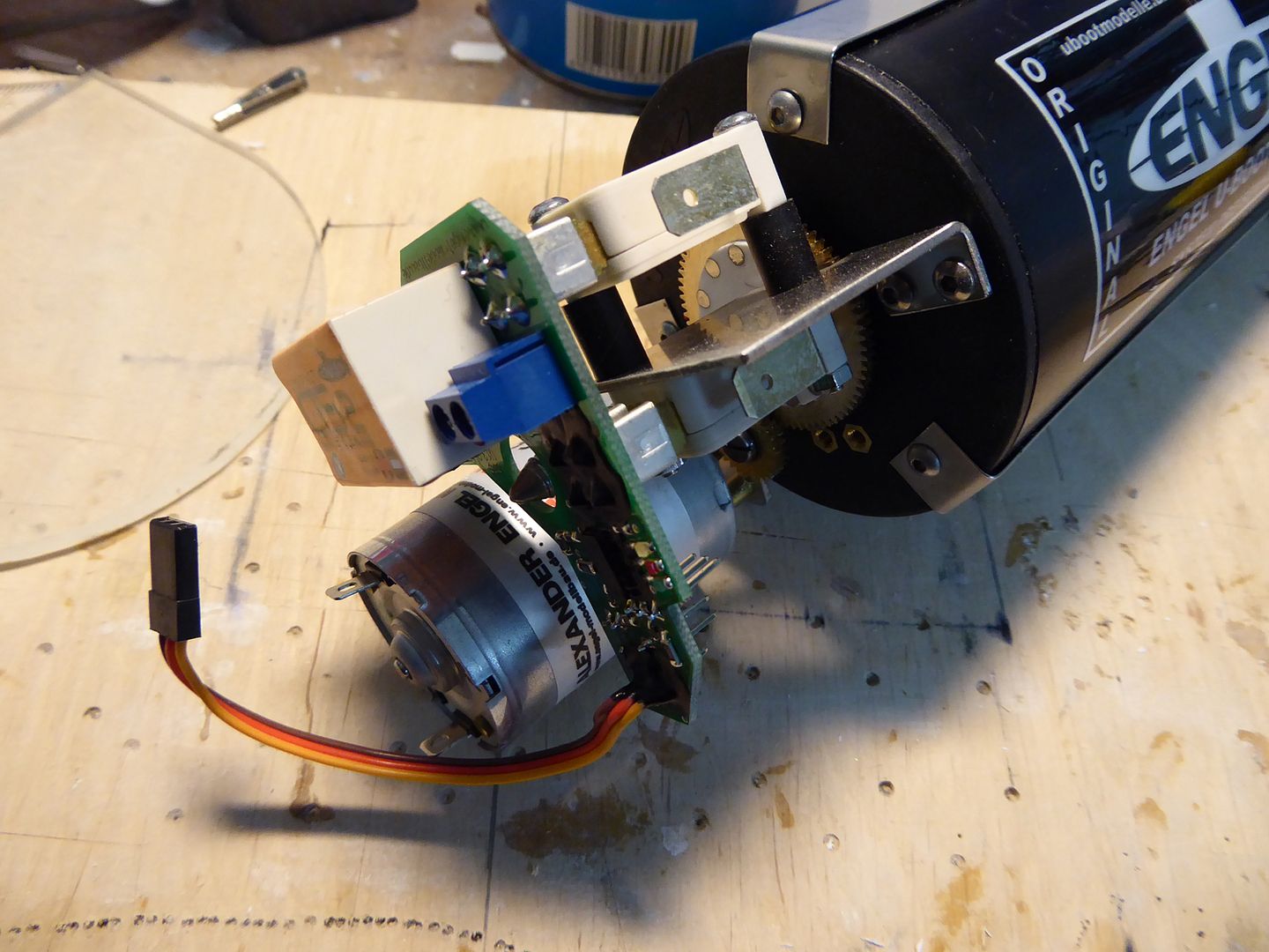
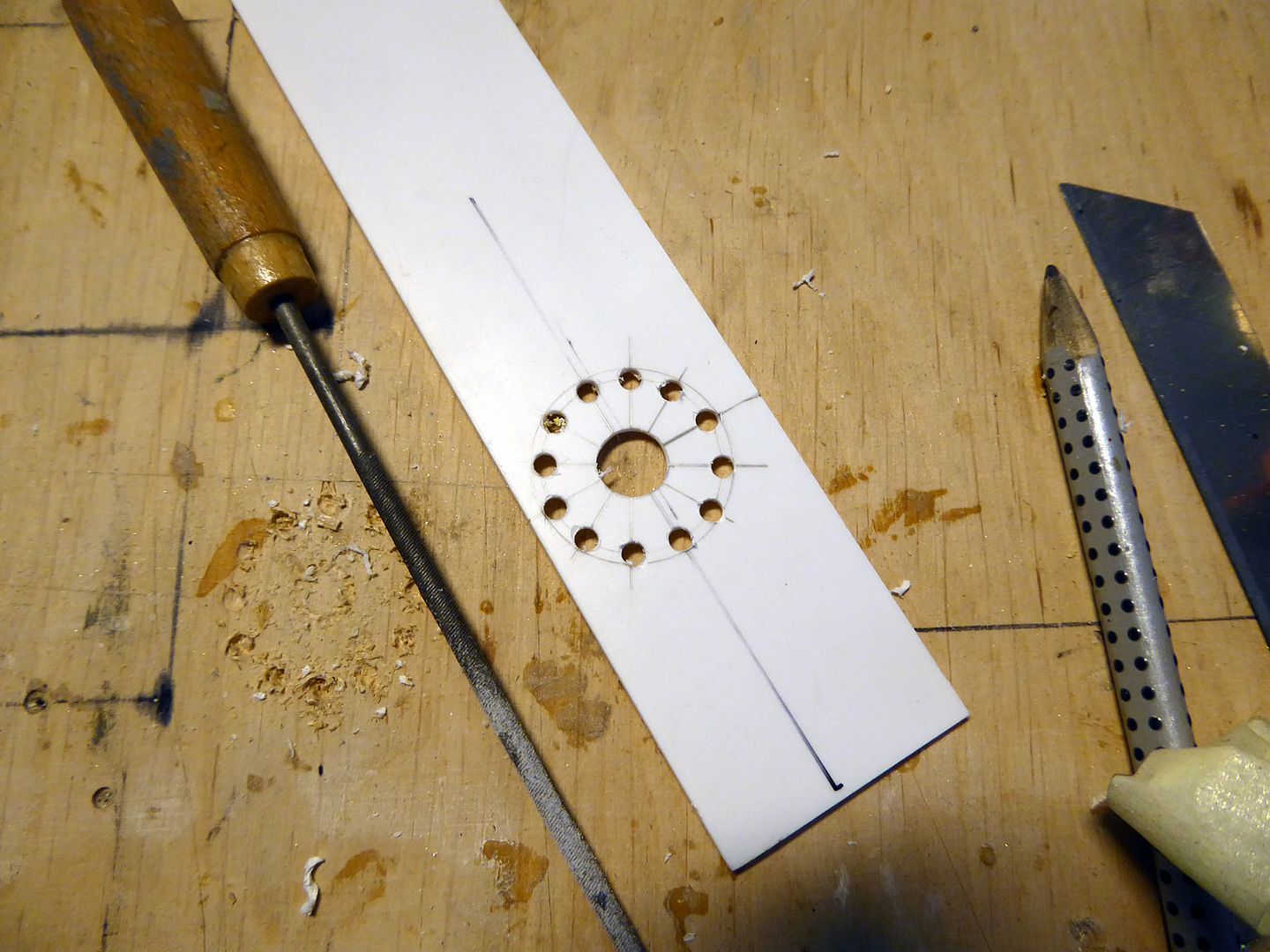
The 1,5 liter Engel piston tank gets a compact control unit with Hall sensor. To get it actuated in a reasonable time, I chose the 540 motor variant. For this combination, magnets have to be glued onto the main gear wheel. Due to their mutual attraction, gluing the 3 mm x 1mm cylinder magnets directly onto the wheel is rather tricky. That�s why I chose to fabricate a magnet wheel. The segments are laid down onto 1 mm styrene sheet material. 12 magnets will be used:
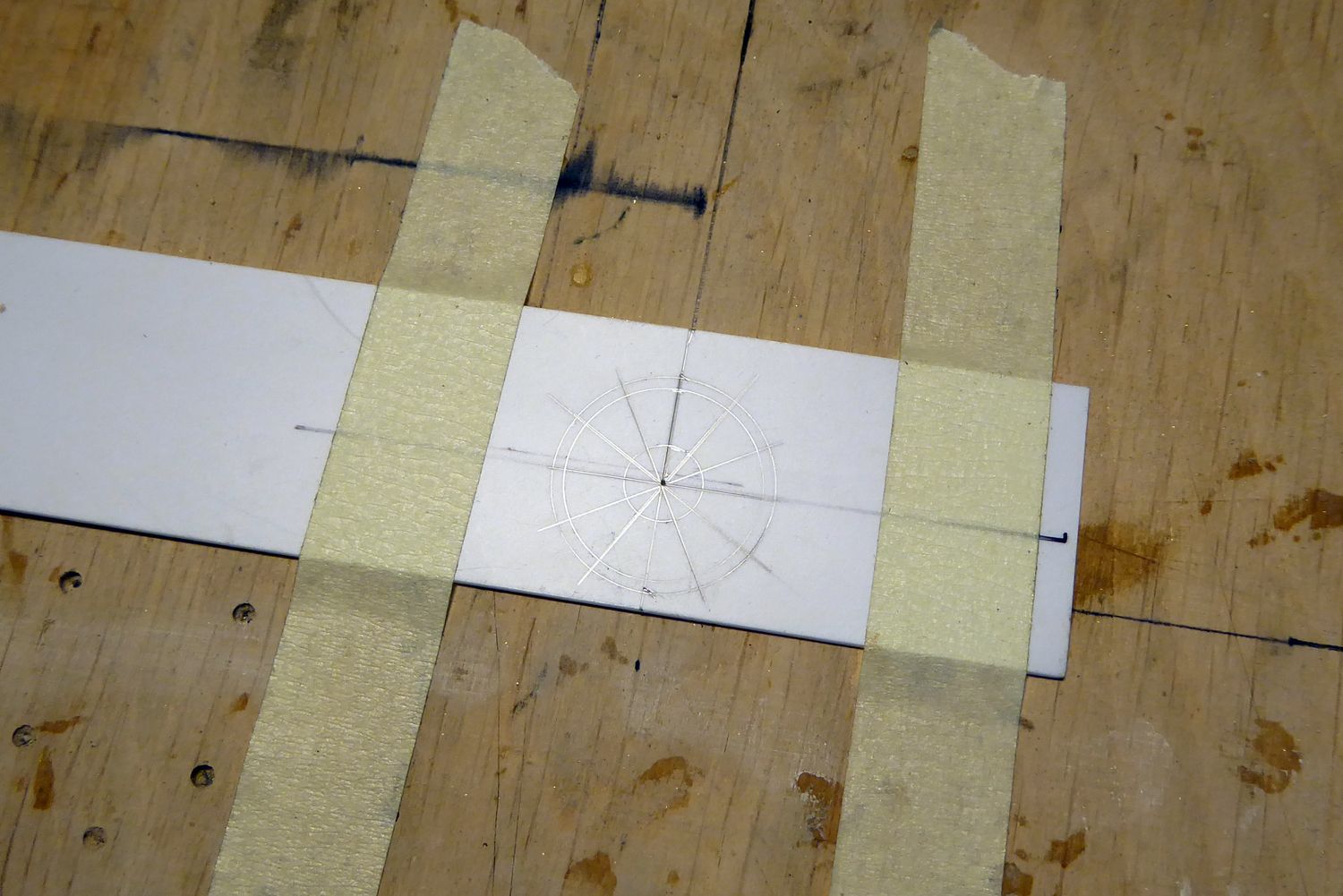
The magnet positions are drilled with a 3 mm drill bit. The central hole has 9 mm diameter.
On a plane plastic sheet treated with release wax the wheel is positioned and the magnets are glued into the respective holes.
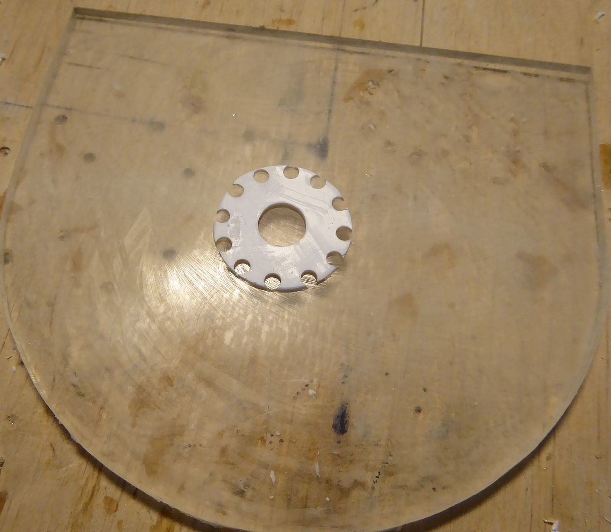
Let cure�
Leave a comment:
-
The linkages to the control planes are done:
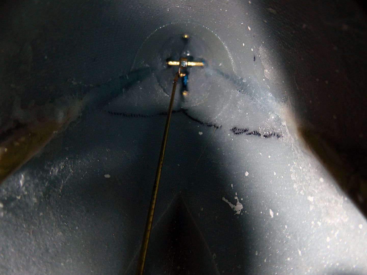
Next is the installation of the pressure switch, which is mounted in a bracket milled out of 5 mm PVC. It�s screwed into place using a M4 thread rod and a distance piece made out of 10 mm thick GRP sheet material:
Leave a comment:
-
To install the dive plane linkage one needs a very long Allen-wrench. Self-made using a 5 mm brass tube and hot glue.
Thread the linkage onto the dive plane shaft, position it right and tighten the screw. This requires patience:
The dive planes are glued onto the shaft. To adjust their distance to the hull, 0,2 mm precision stainless washers are used.
The linkage to the servo shaft is done using a piece of 3 mm diameter brass tube and soldering:
And this is how the thing works in real:
Leave a comment:
-
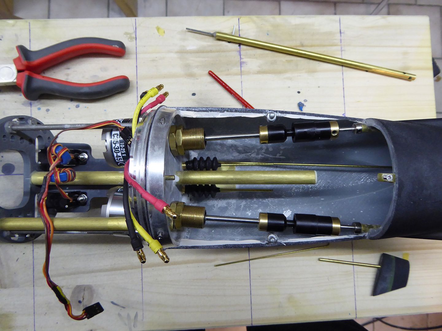
The two servos are secured from below using 3 mm stainless steel screws:
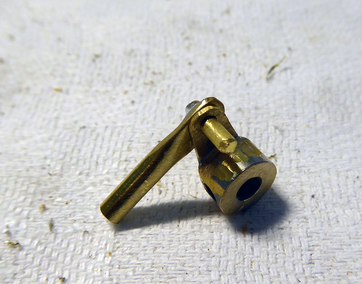
2 mm brass rods with clevises make the linkage:
The feedthrough is sealed using Engels rubber bellows:
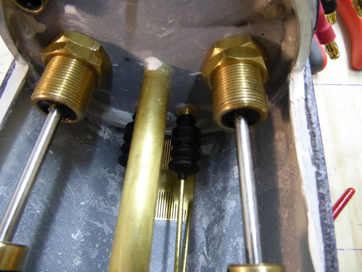
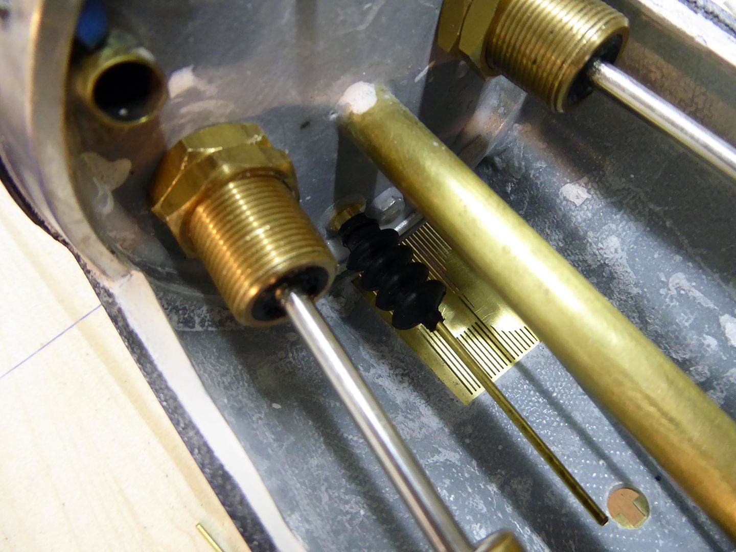
Tight fit but doable:
Leave a comment:
-
The painting and weathering of the boat is done and the final 2-component clear coat (matt) is applied. NO comes the fitting of the boat:
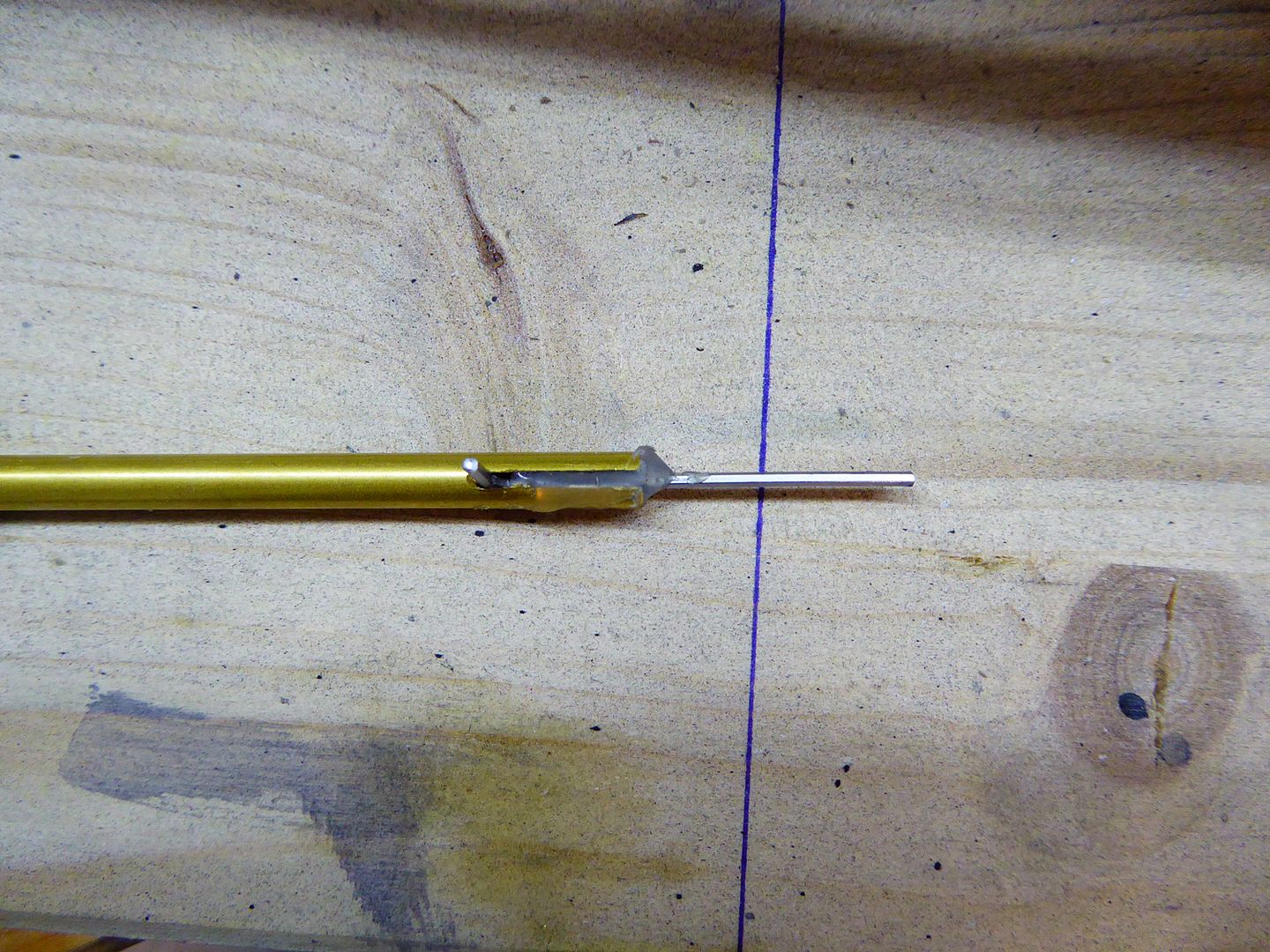
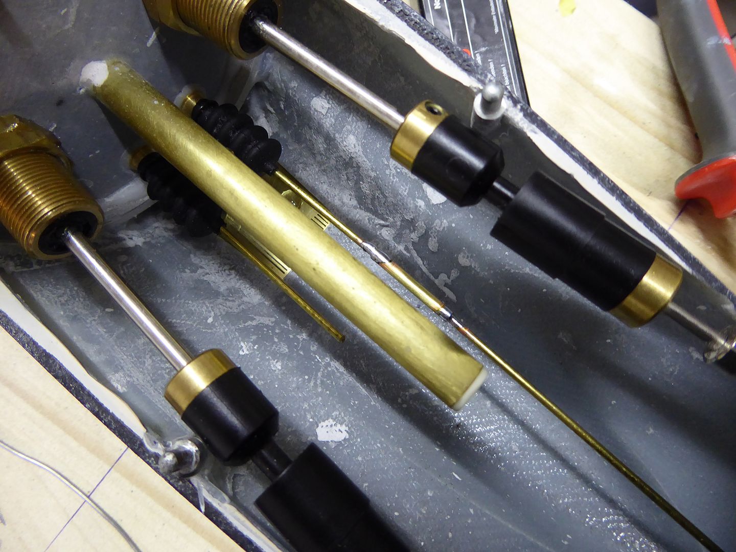
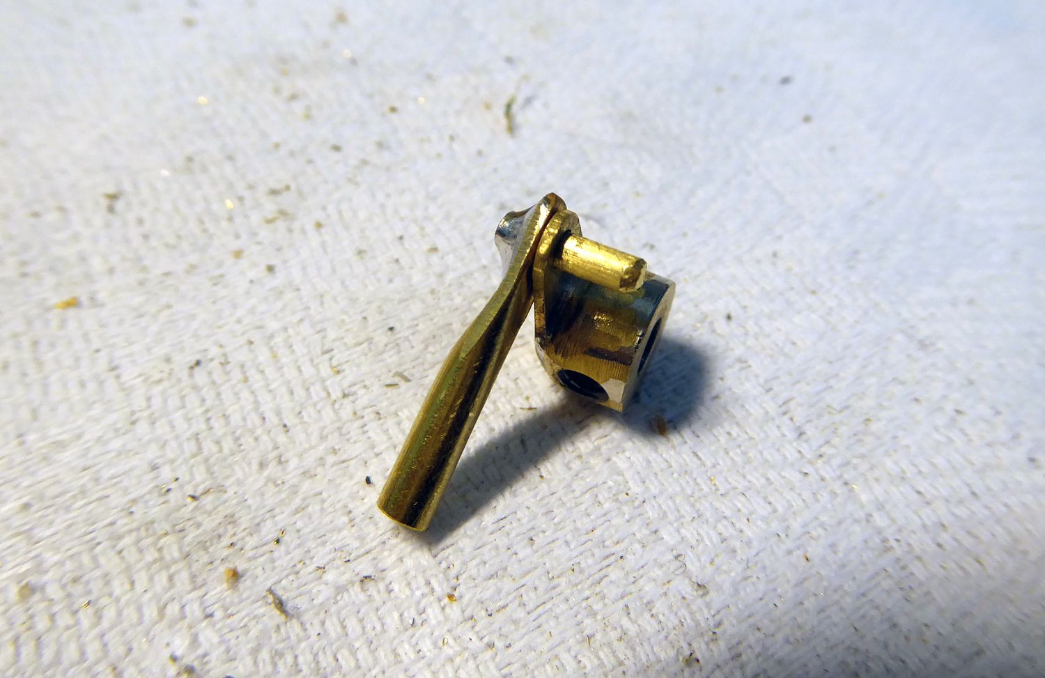
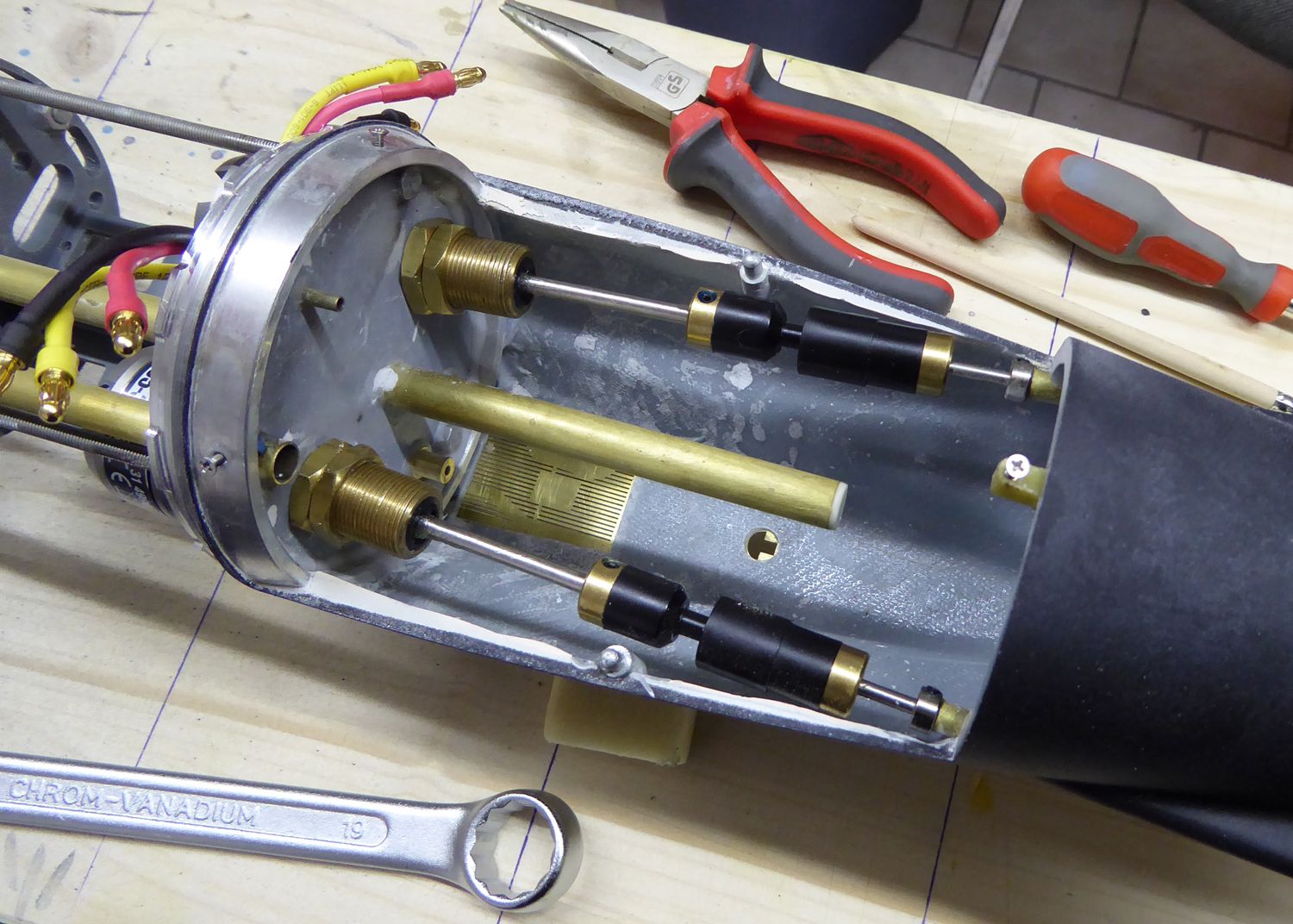
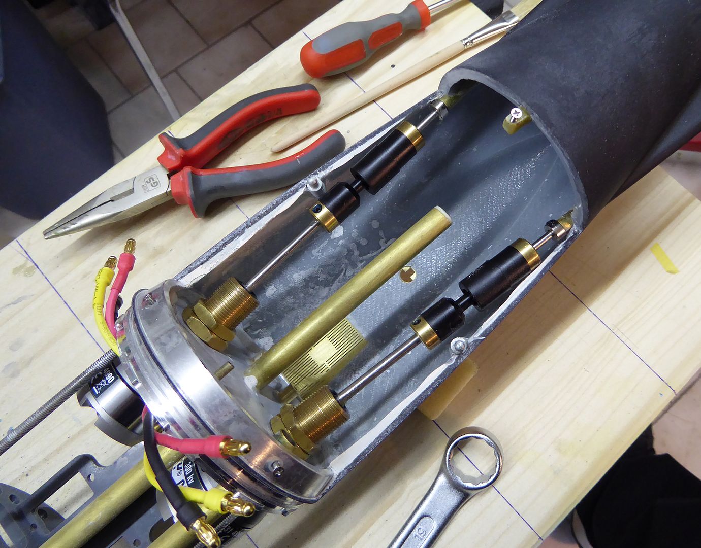
Because of the limited space, the linkages are custom-made. A 3 mm brass tube is hammered even and a 2 mm diameter brass stud is soldered into it. A 3 mm brass set collar is soldered to a 2 mm thick brass linkage and we have it. Needed two times.
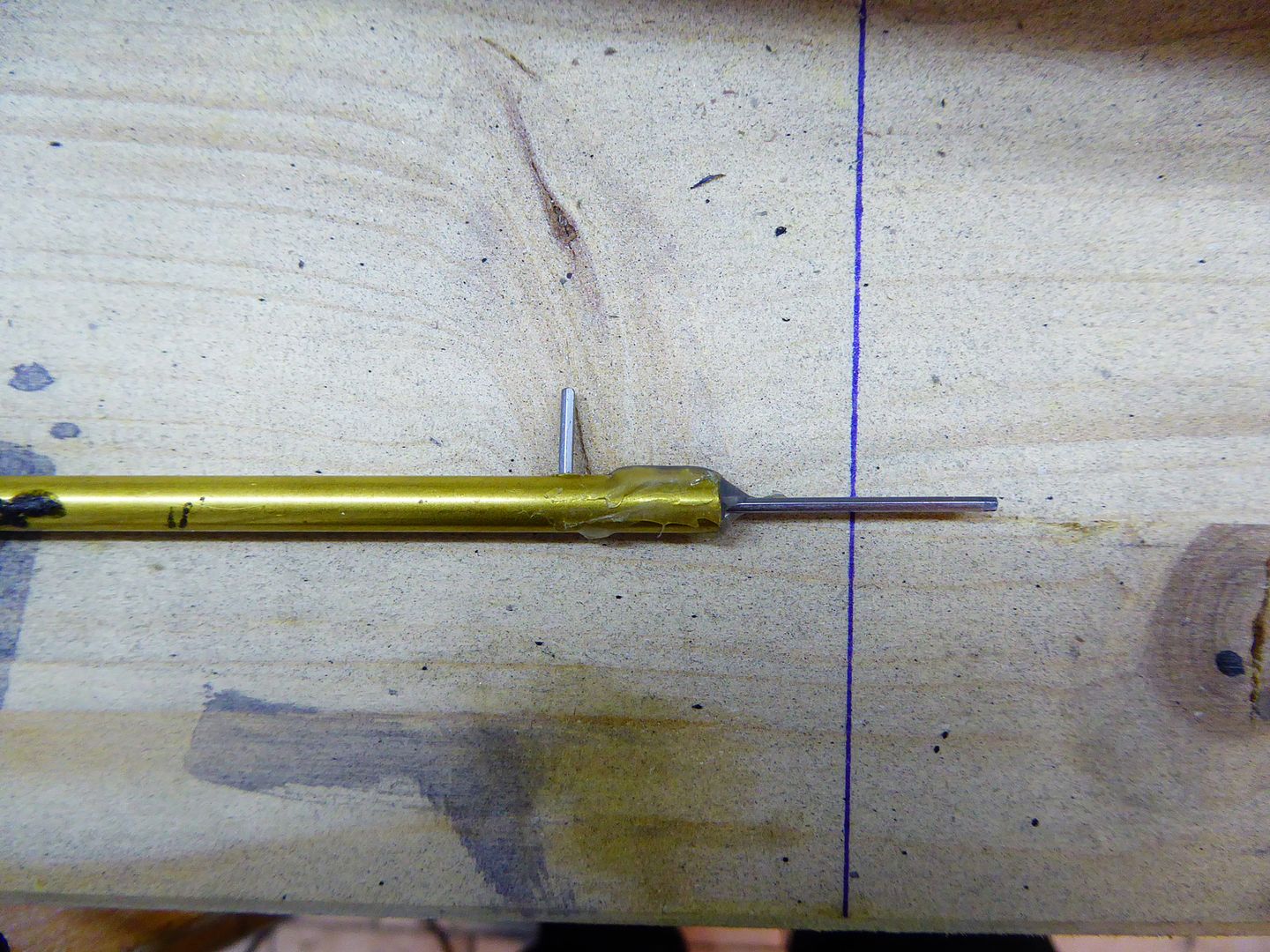
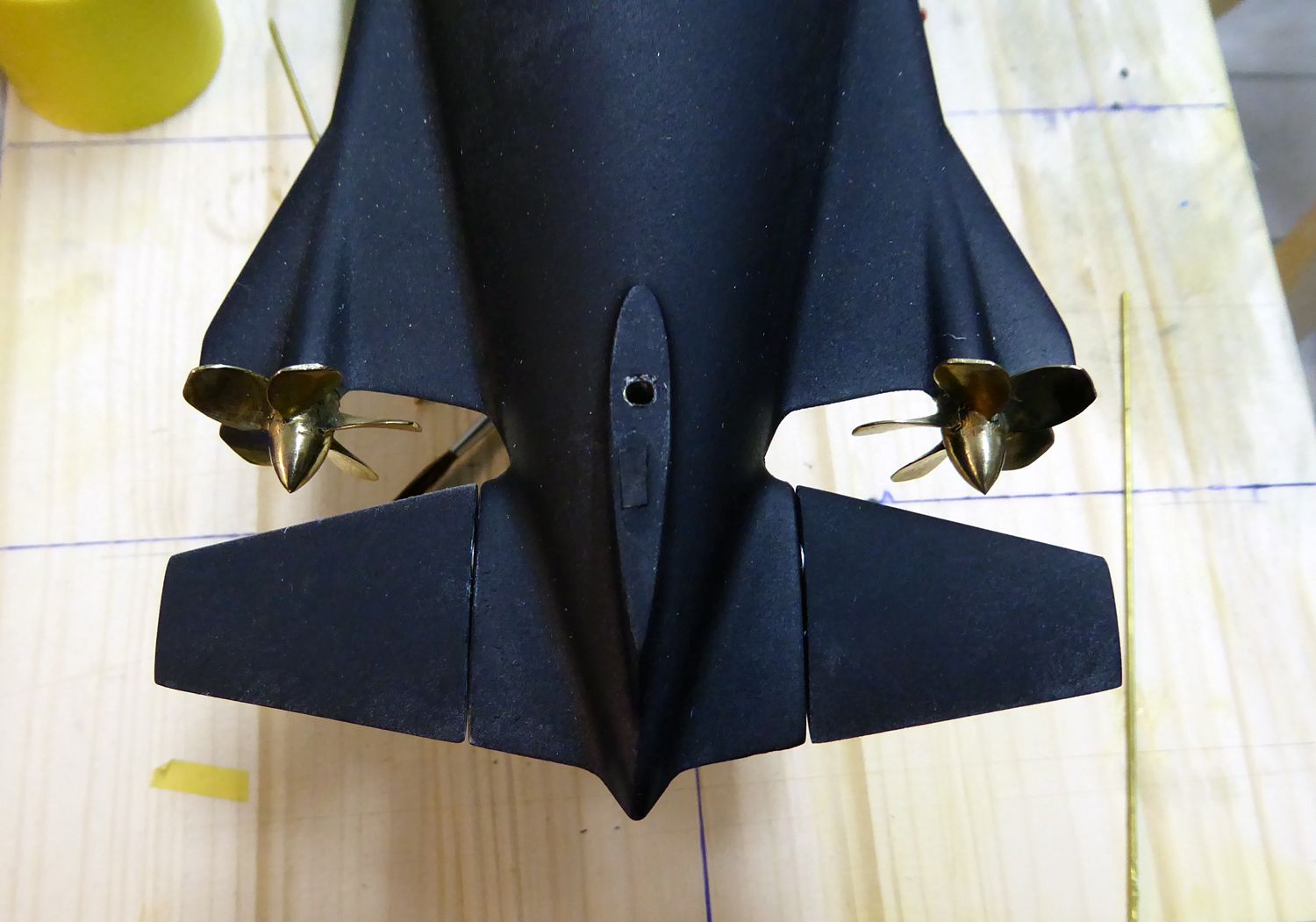
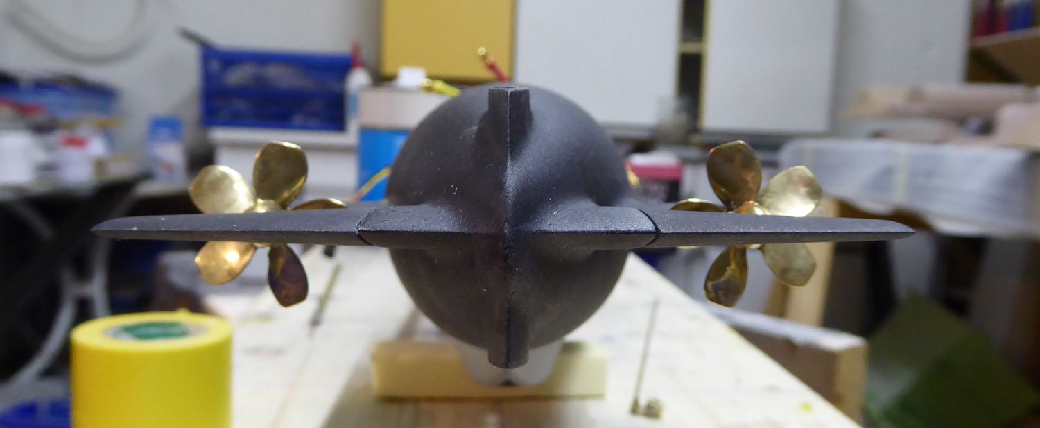
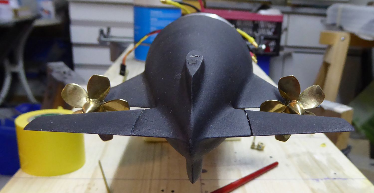
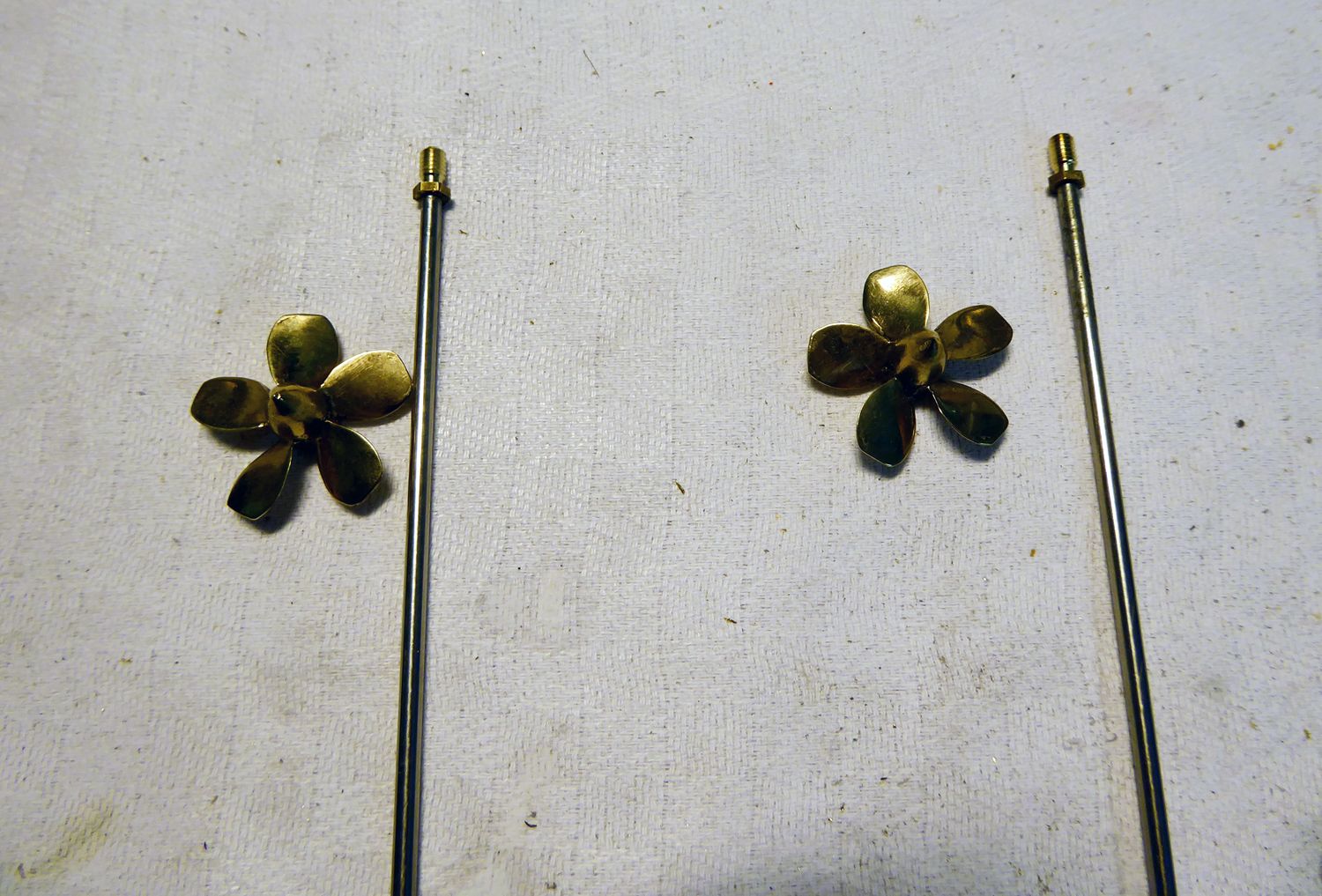
The threads of the propeller shafts are shortened and the props are secured using Loctite blue. The prop shafts are put into the stern tubes using plenty of grease. Everything is secured using set collars.
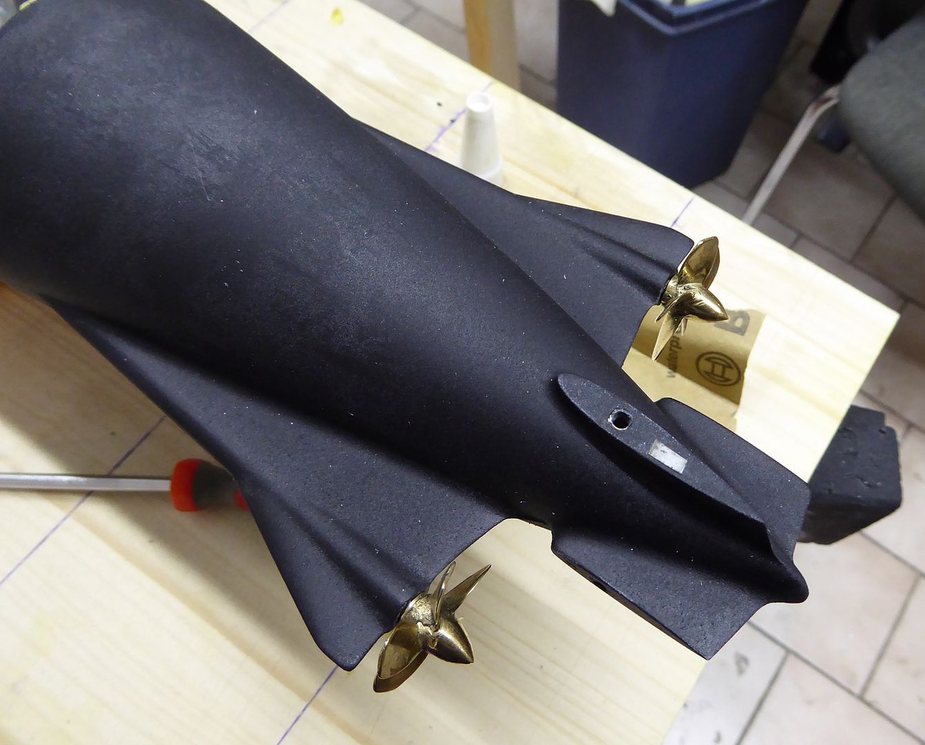
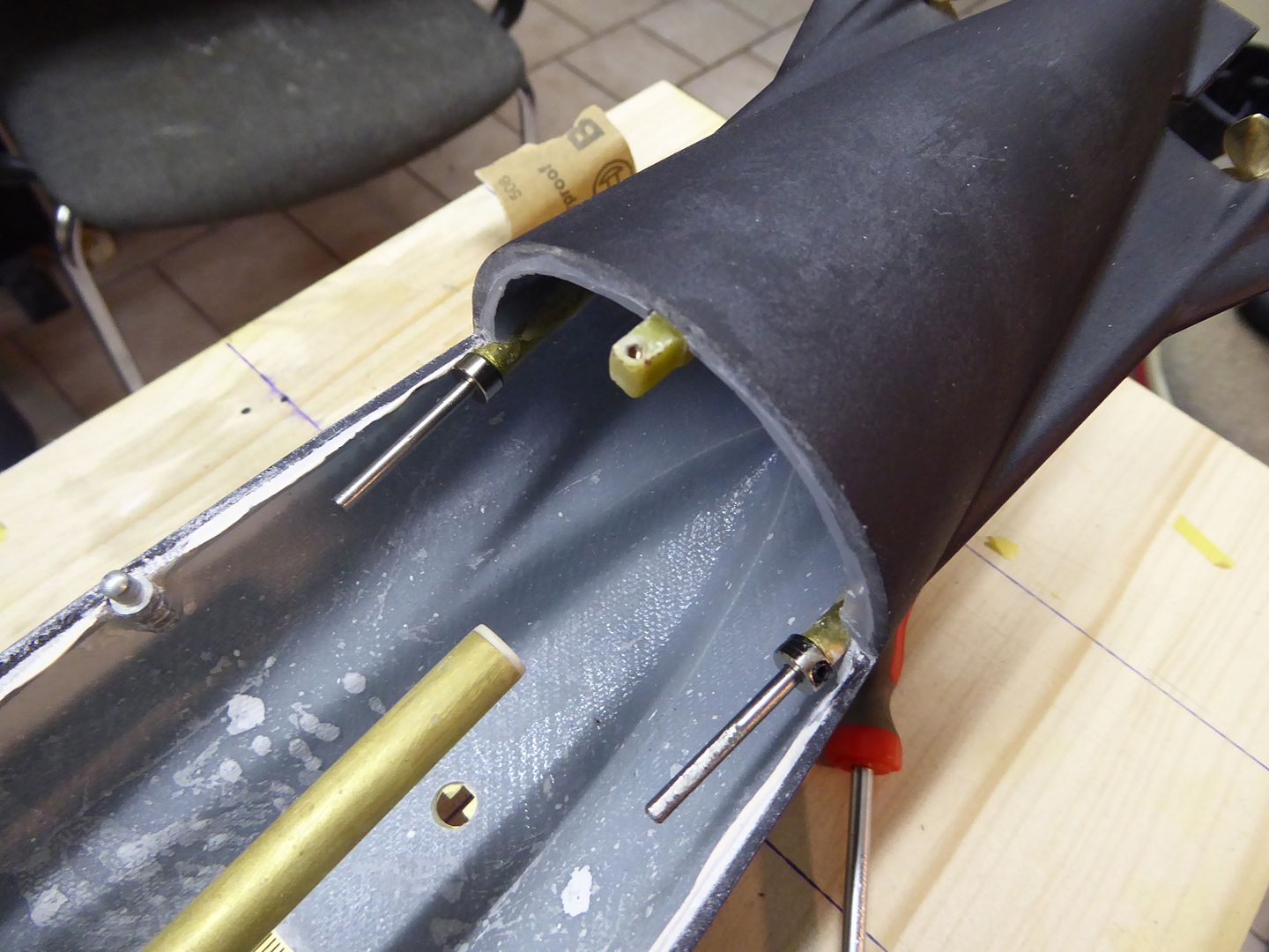
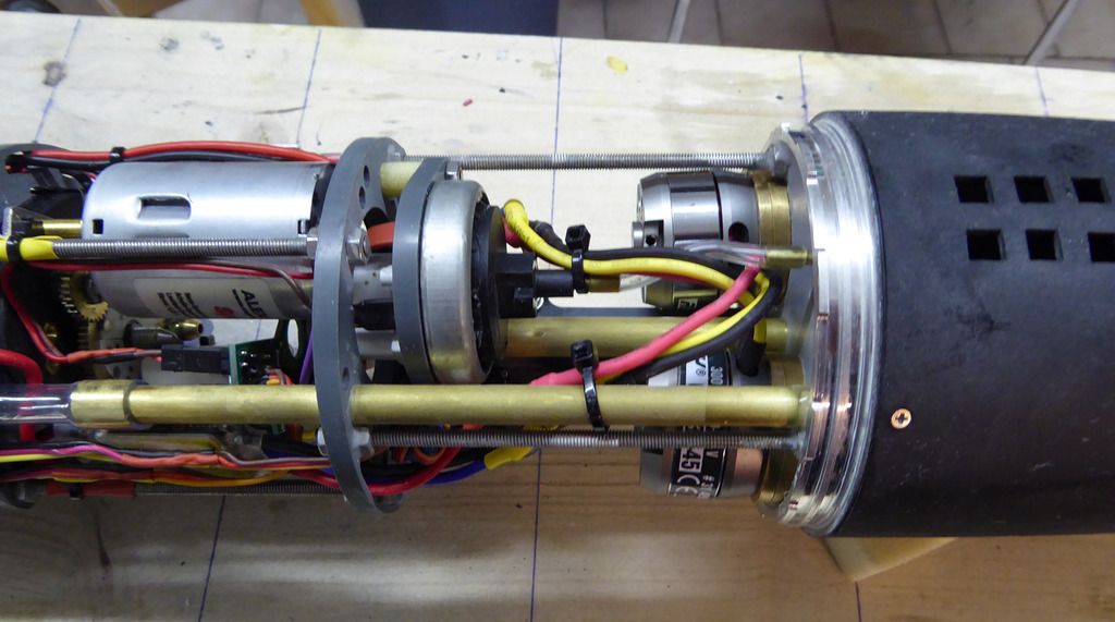
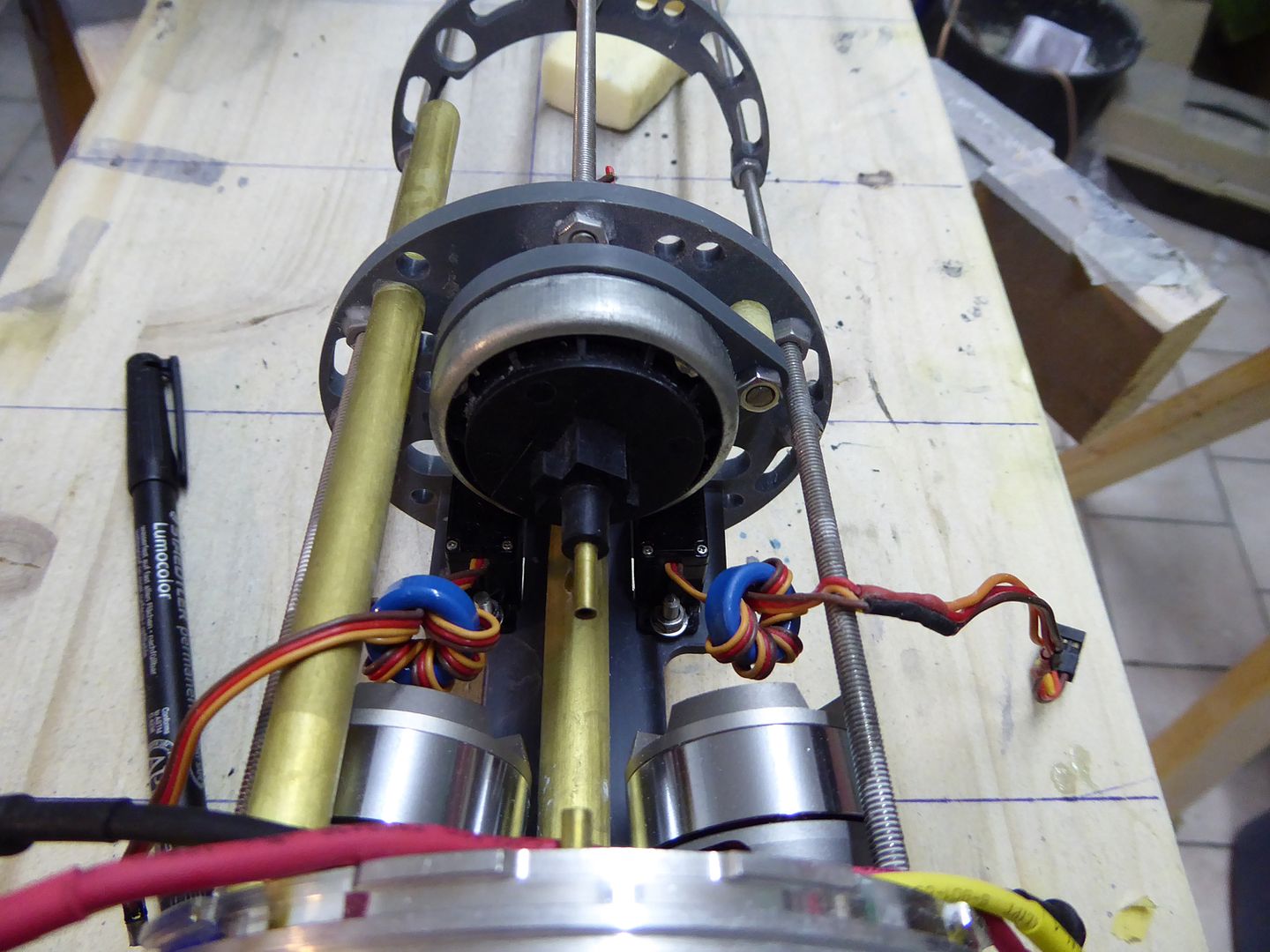
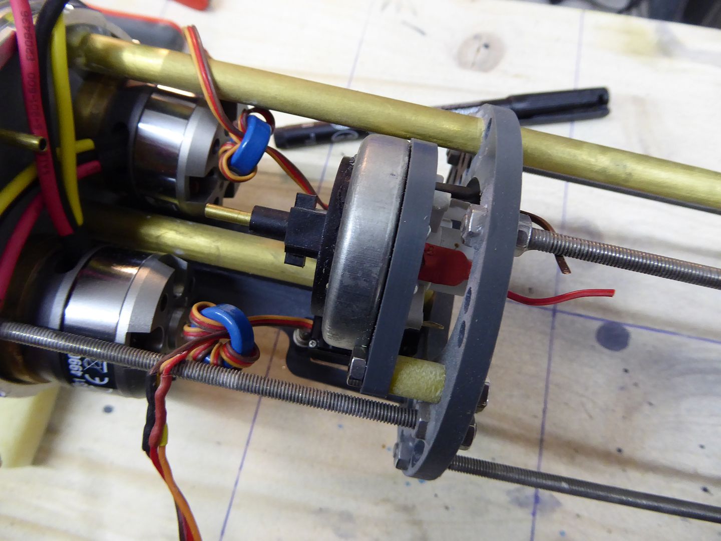
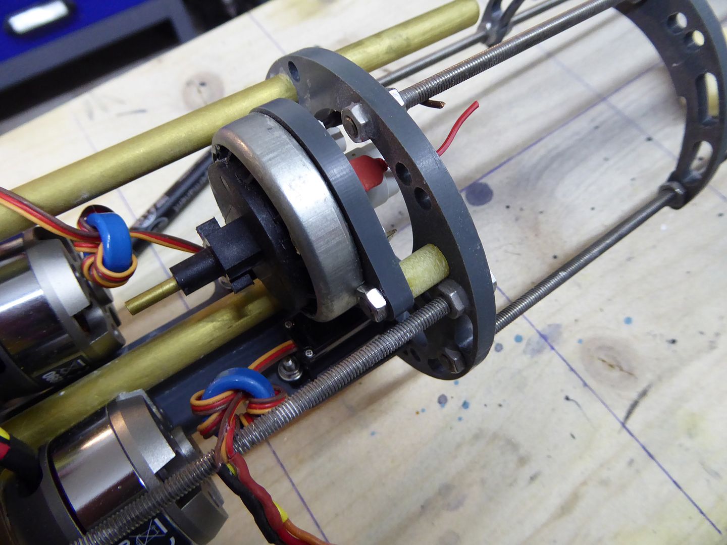
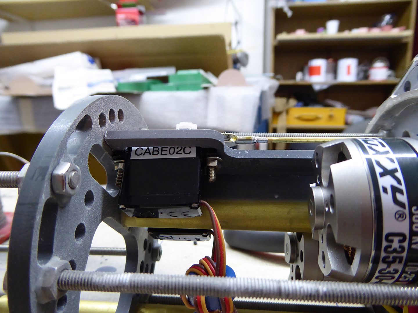
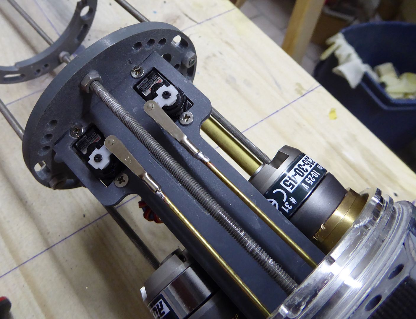
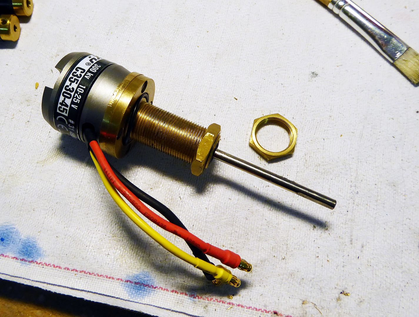
The watertight motor units are put into place and secured using M16 brass screws. Latter are locked with a second pair of nuts. Loose cardan joints transmit the torque and allow for thermal expansion:
 #
#
Leave a comment:


Leave a comment: