USS Nautilus - Final Edition

Collapse
X
 
  • Time
  • Show
Clear All
new posts

  • DrSchmidt
    replied
    After fitting the service hatch, the first section of the inner structure can be glued into the stern section. In particular, the motor bulkhead has to be glued into the inner ring of the bayonet catch. Actually that is simpler than it might seem. The watertight motor feedthroughs are put into the holes of the motor bulkhead and locked. I use my custom-made ones from the prototype:


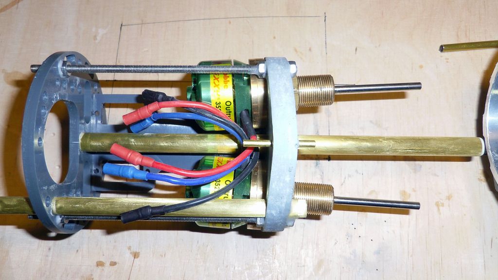
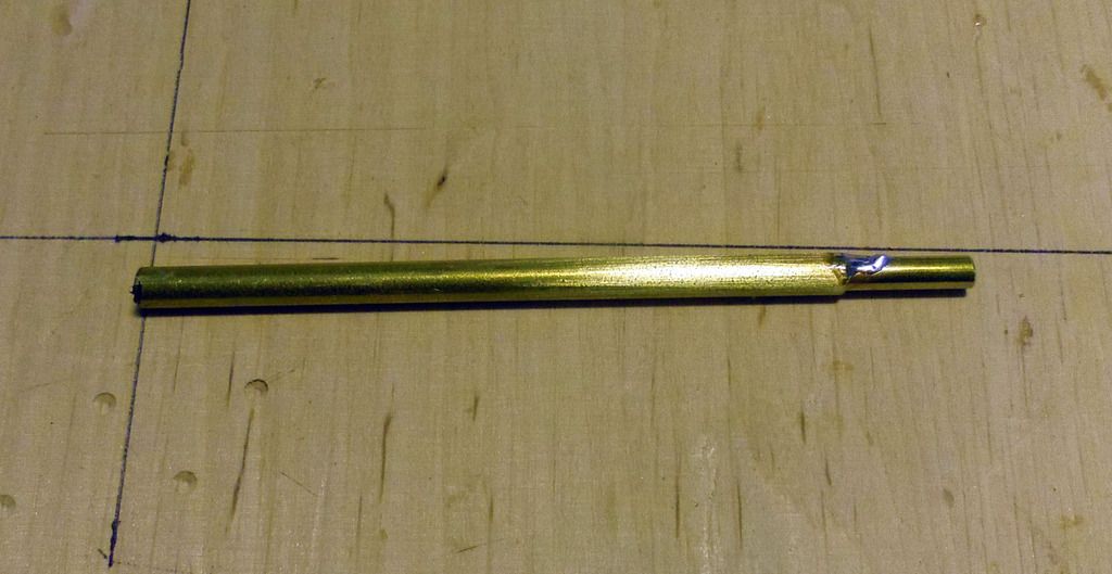
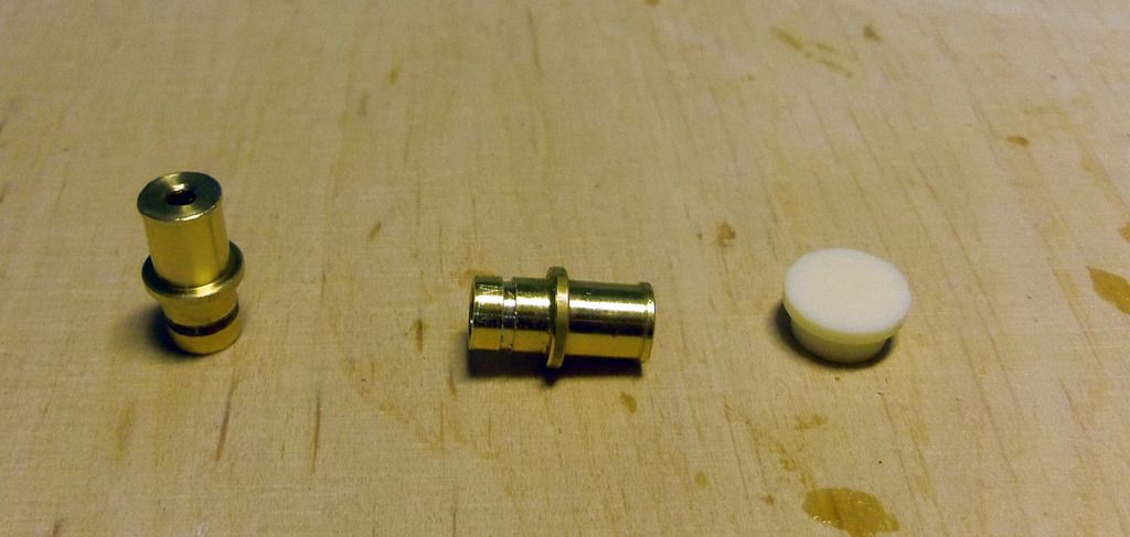
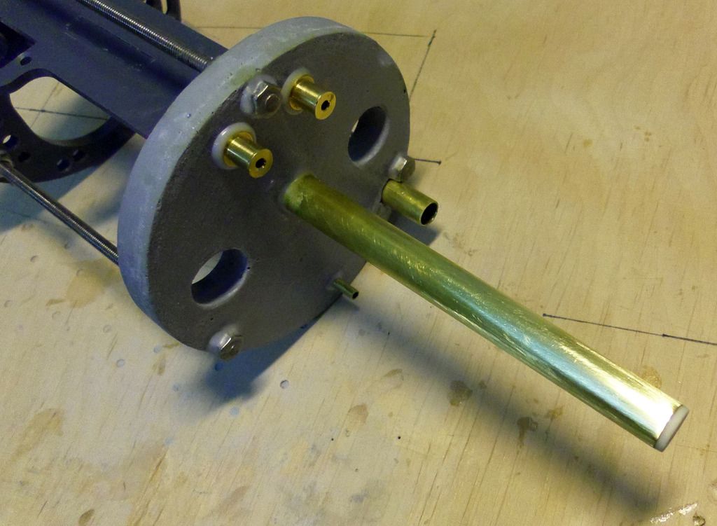
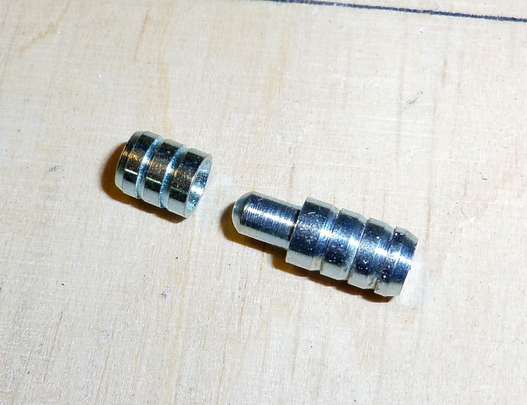
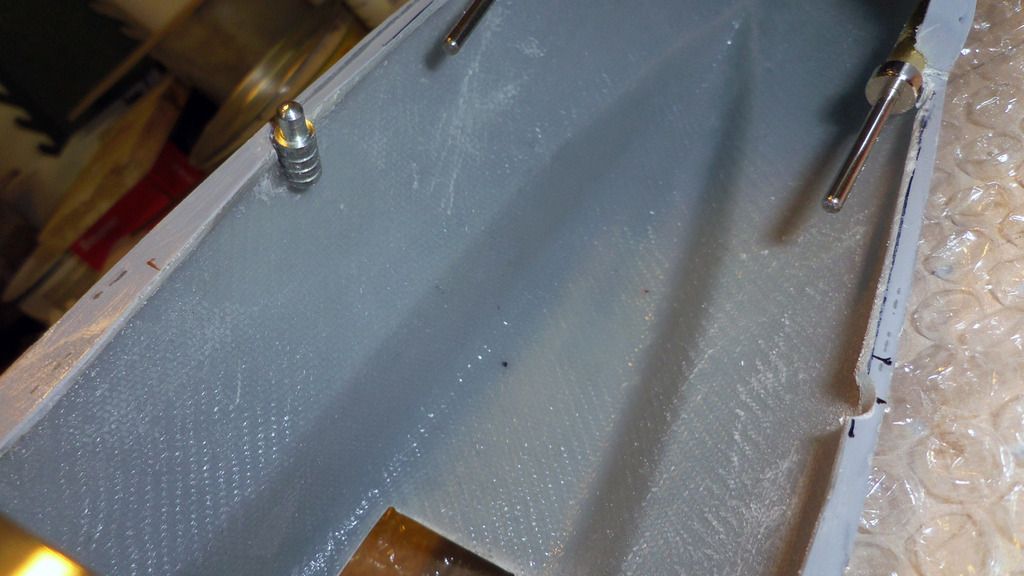
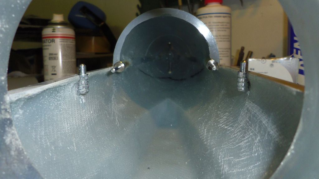
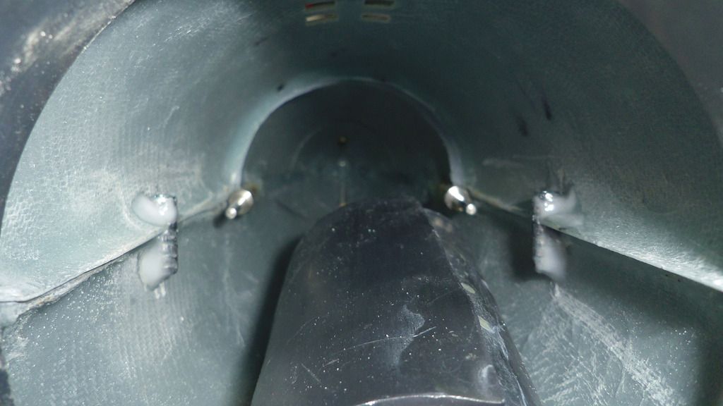
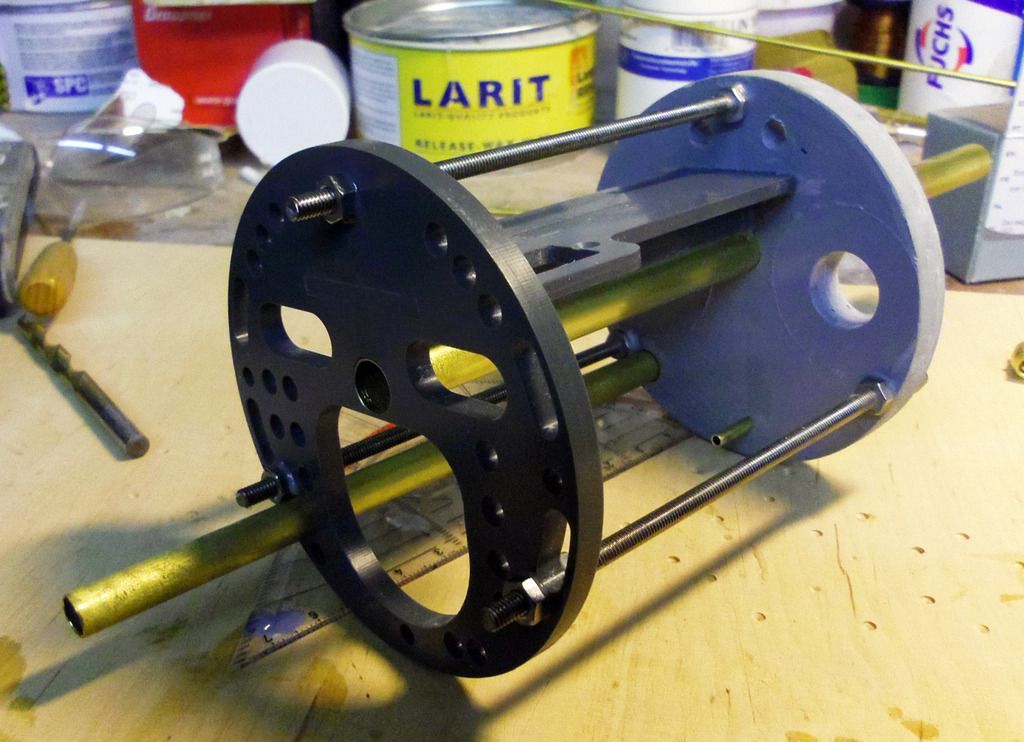
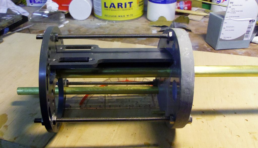
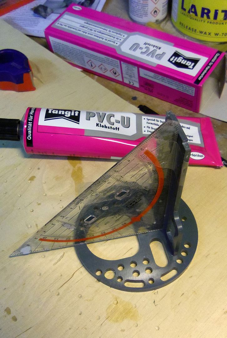
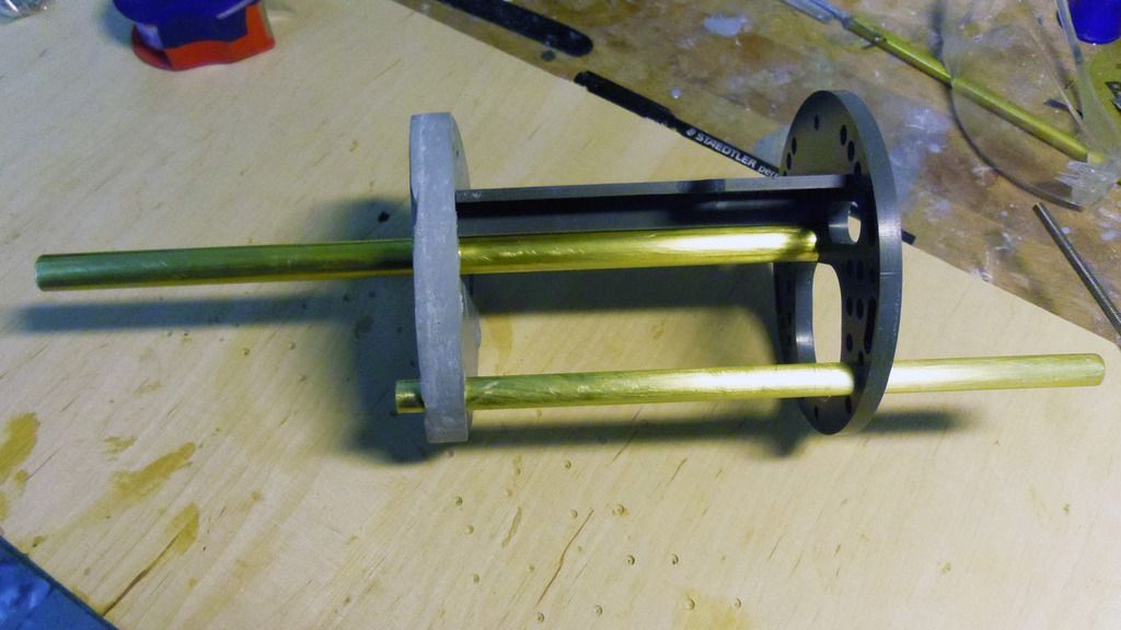
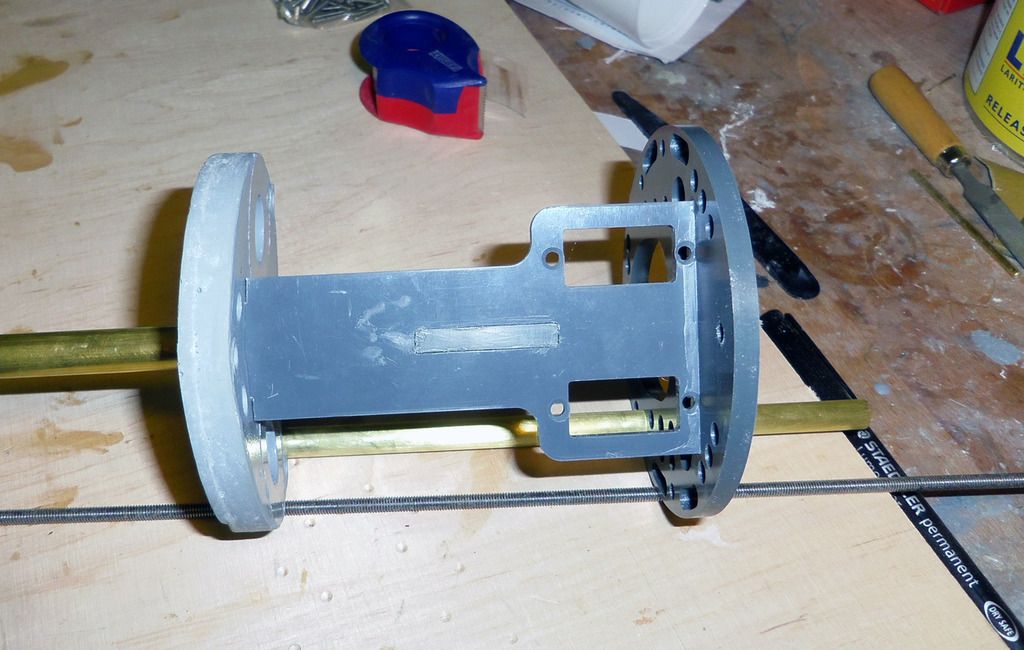
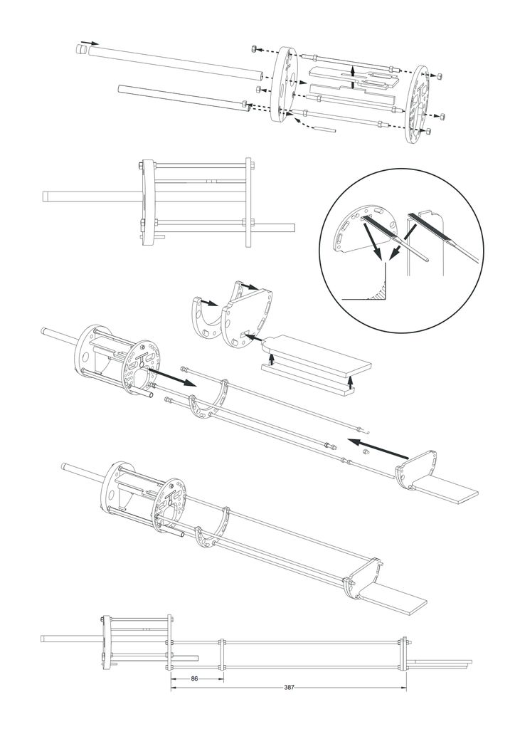
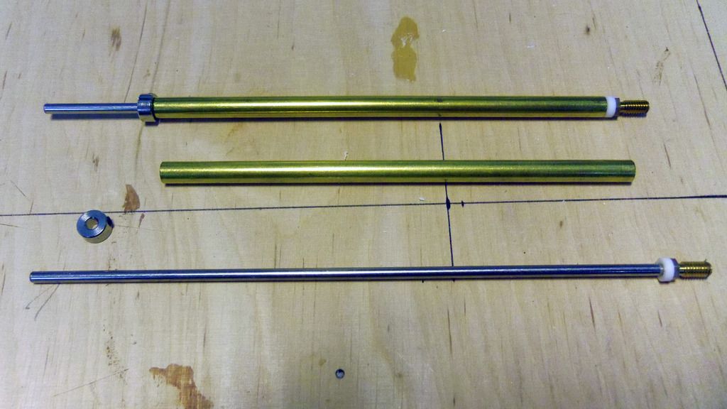
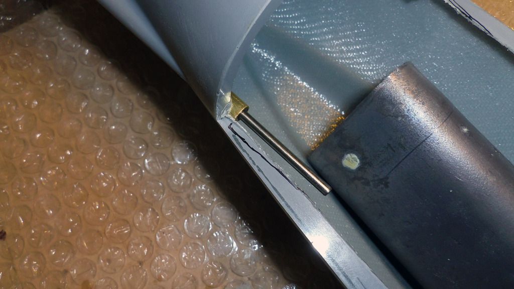
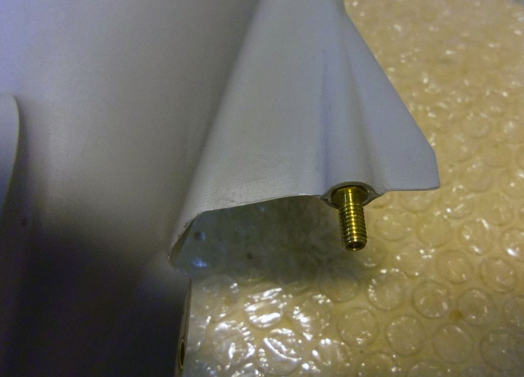
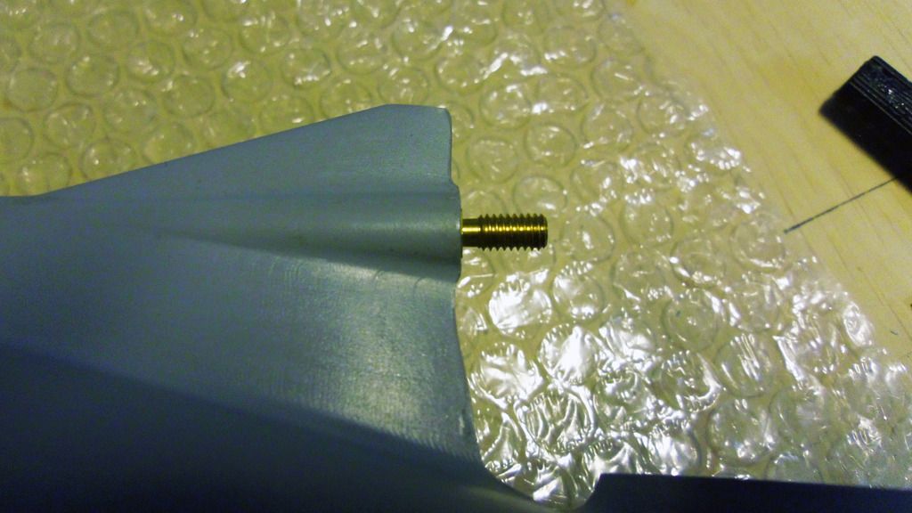
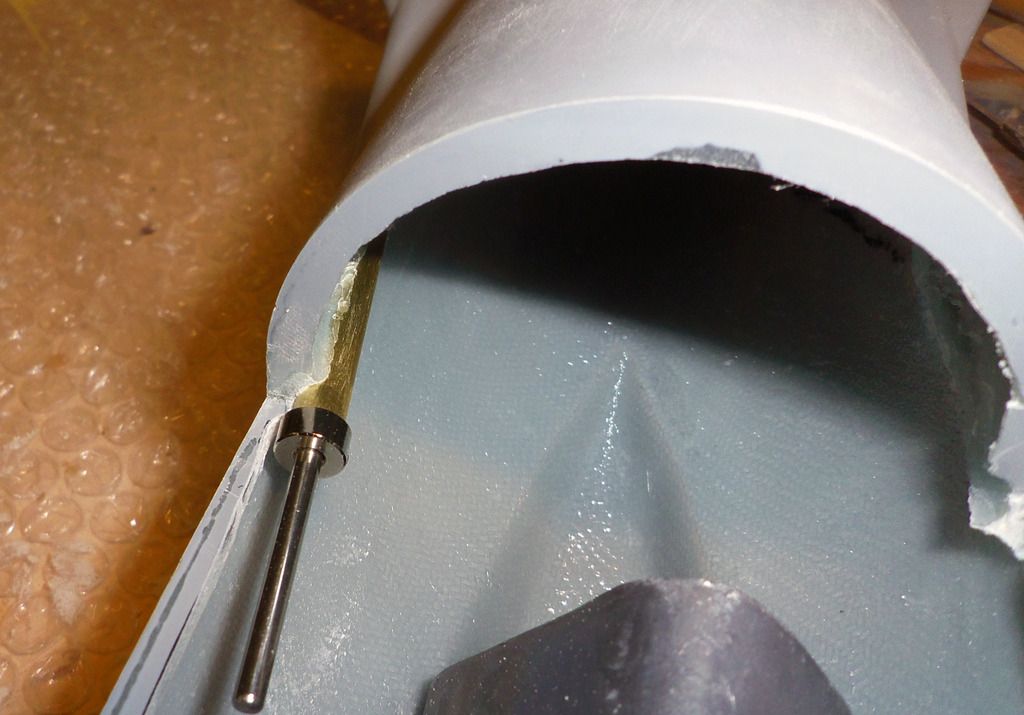
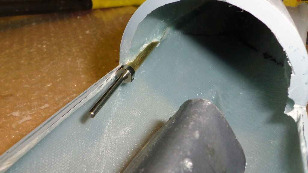
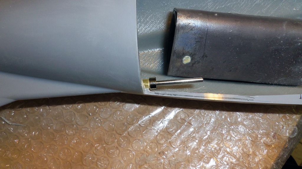
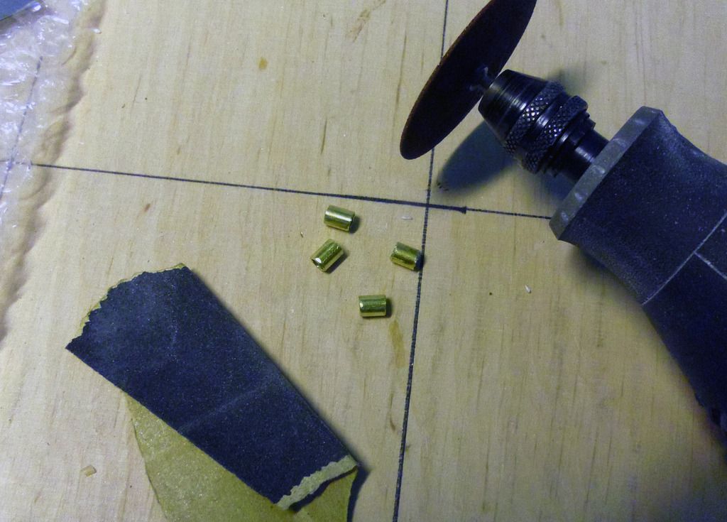
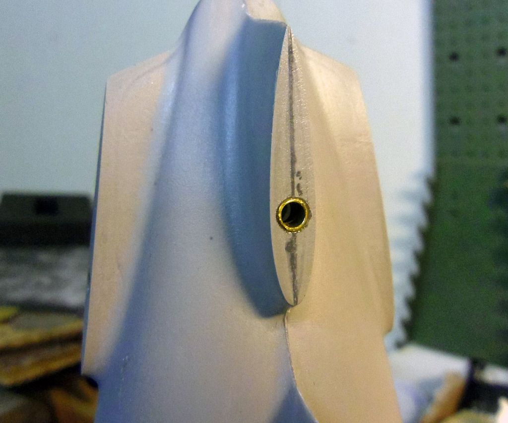
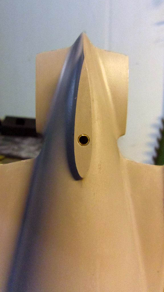
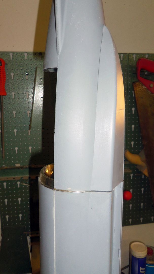
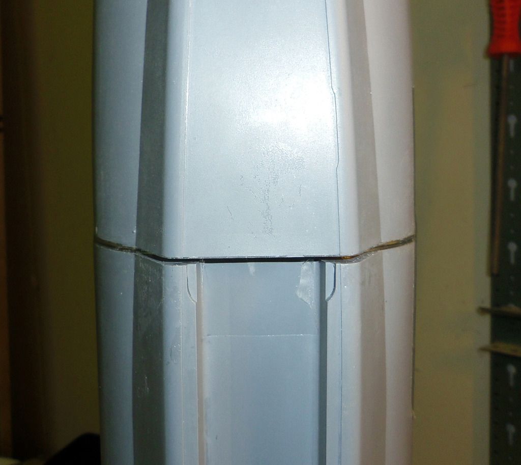
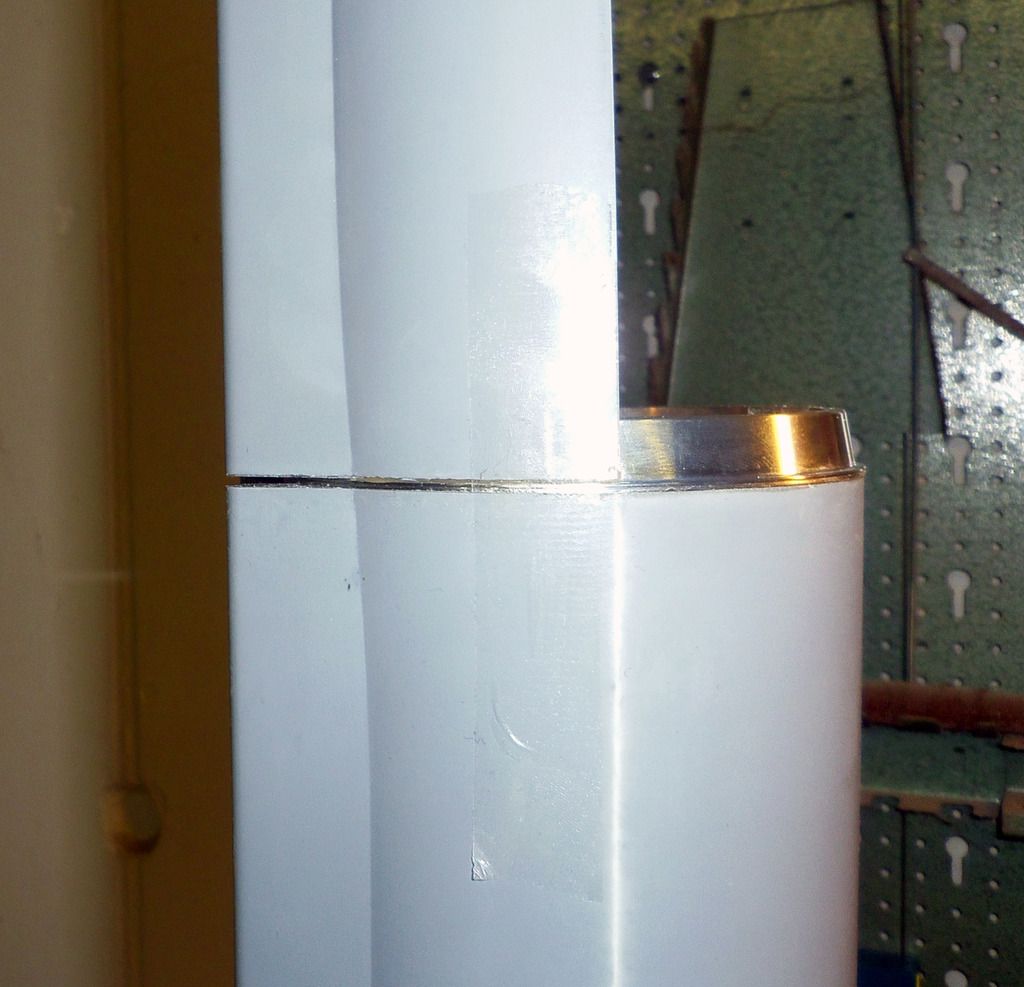
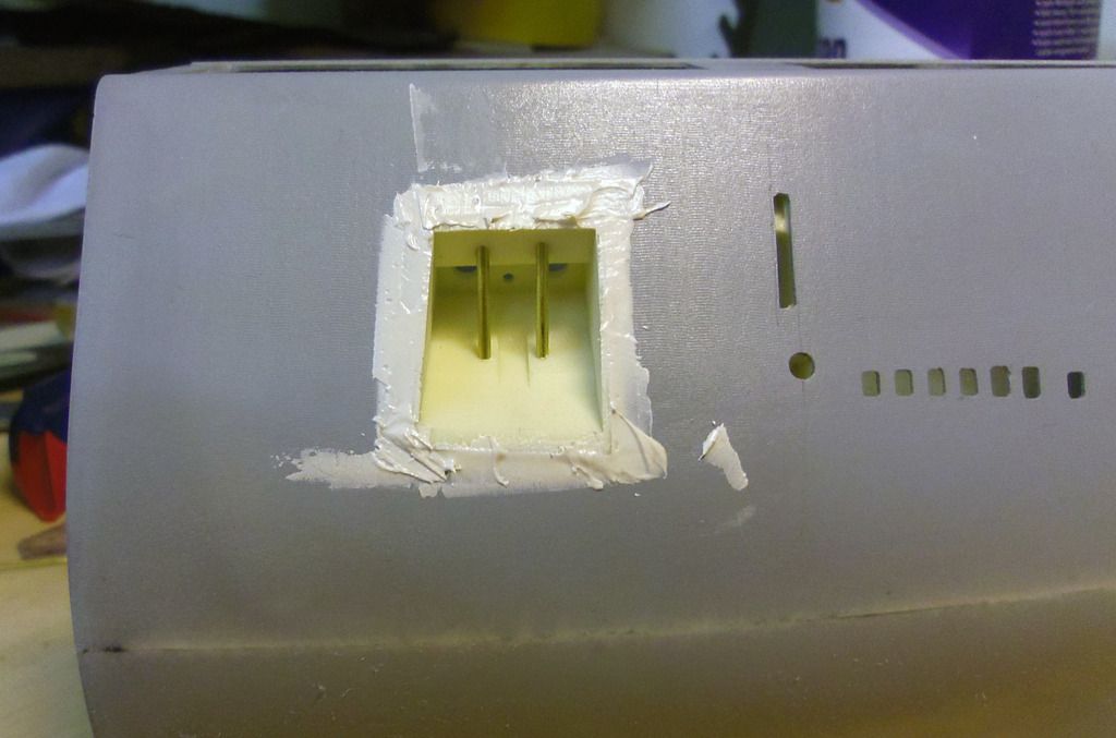
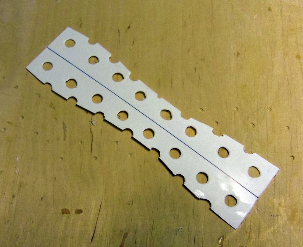
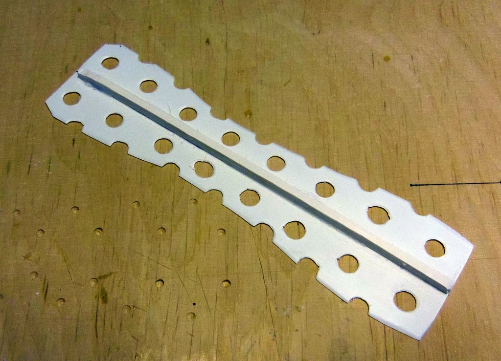
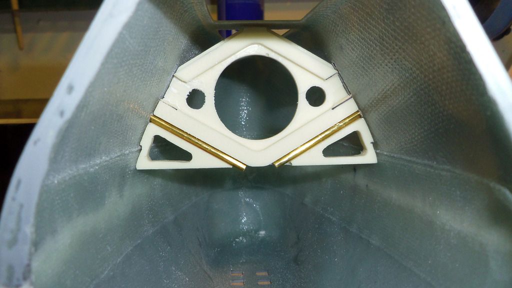
    Because of the v-shape of the motor bulkhead and the position of the motors, the propeller shafts and the motor shafts are perfectly collinear when the bulkhead is correctly positioned. To reach this alignment, I fabricated two auxiliary tools. They are basically 4 mm brass tubes put into 5 mm brass tubes. The tubes are glued or soldered together. The 4 mm tube is put onto the 3 mm propeller shaft, then the 4 mm motor shafts are put into the 5 mm end of the tool until everything sits loosely. The motor bulkhead is in the right position.


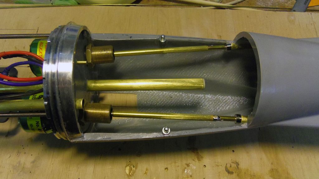
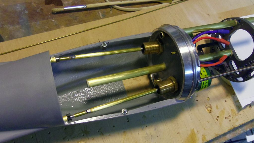
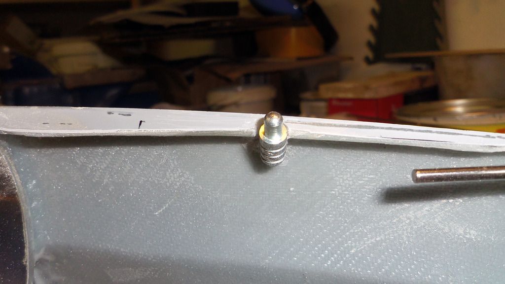
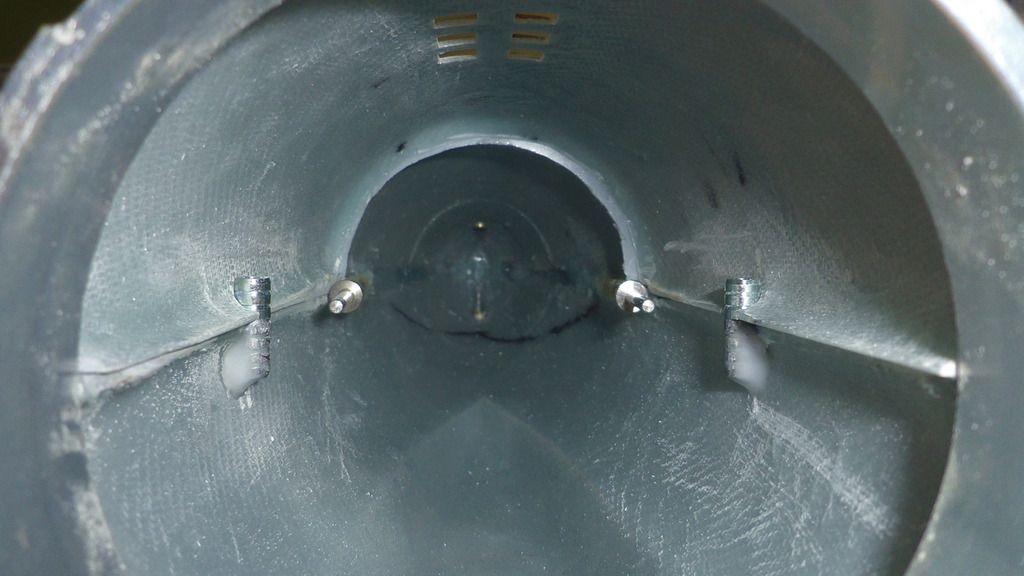
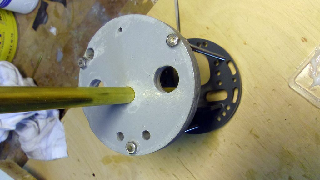
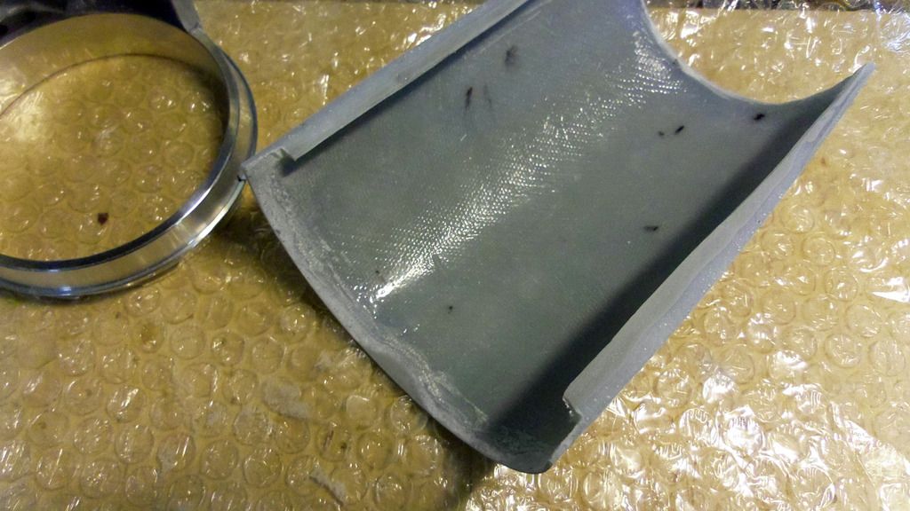
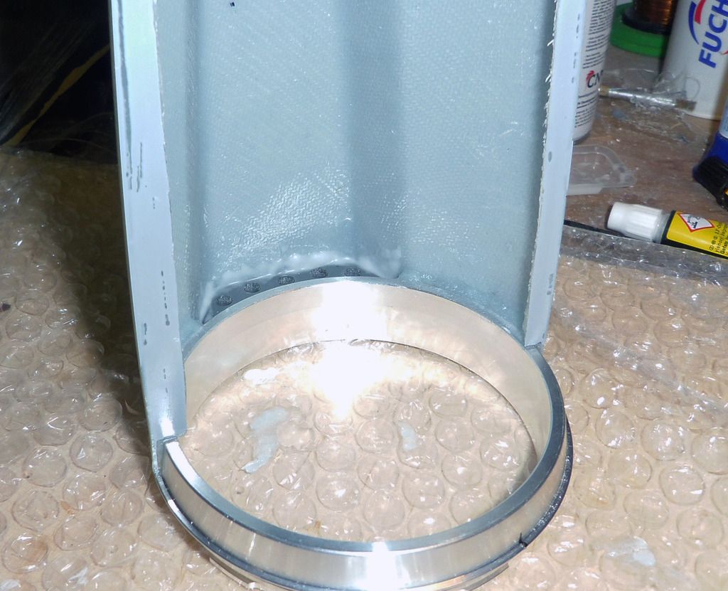
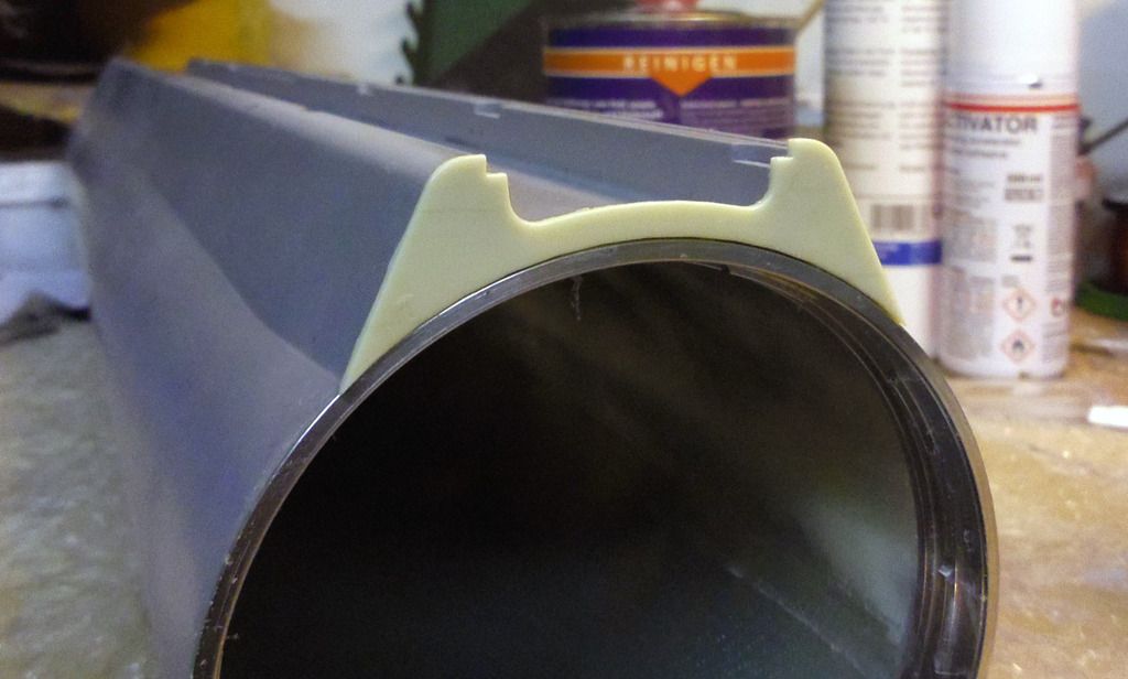
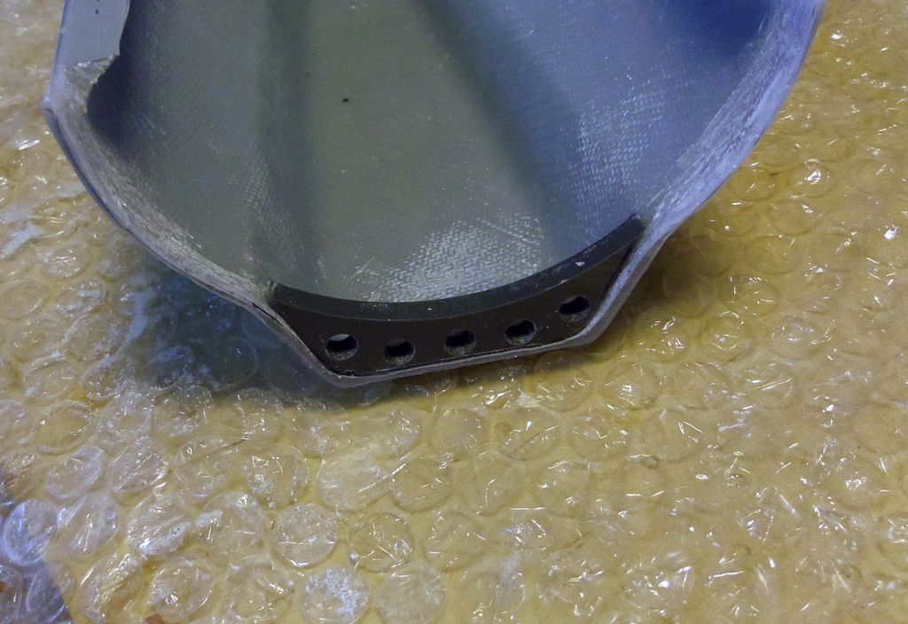
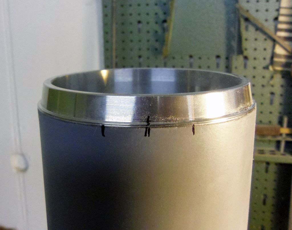
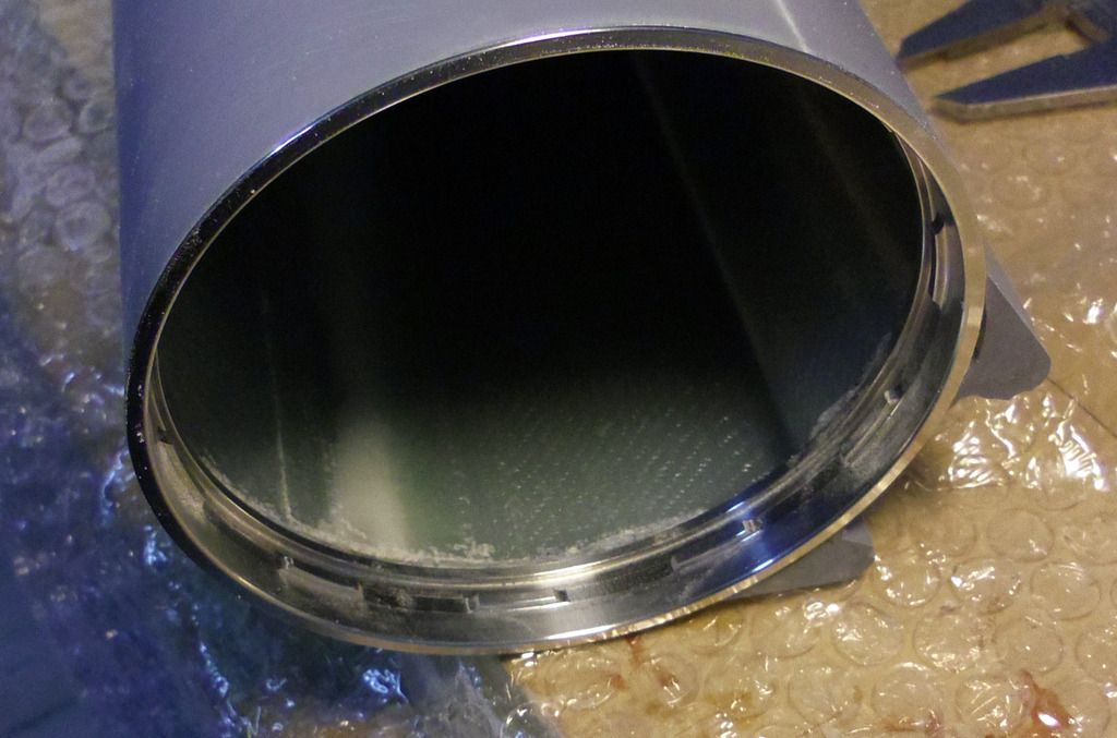
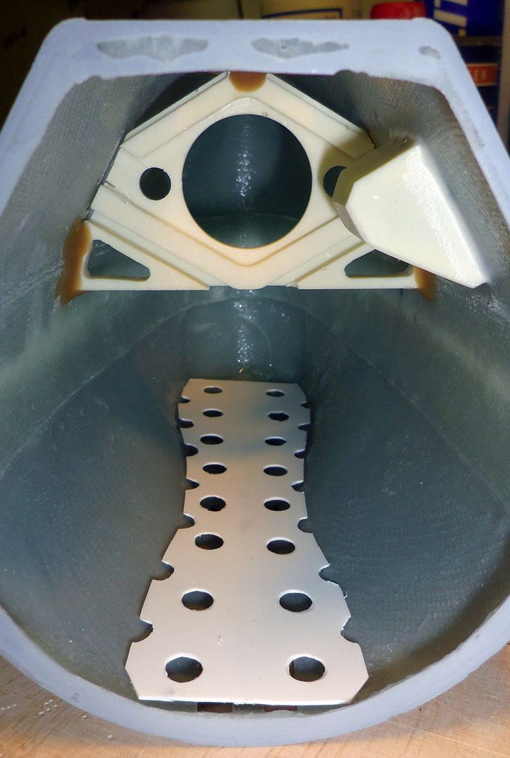
    The inner ring of the bayonet catch and the motor bulkhead are sanded with coarse sandpaper and then cleaned with acetone. A generous amount of extreme-strength epoxy is put into the middle of the inner ring. Then put the motor bulkhead into the ring using the auxiliary tools. Check if everything is positioned correctly, then let thoroughly cure everything.


    Leave a comment:


  • DrSchmidt
    replied
    To fit the service hatch tot he bayonet ring, the ring and the adjacent GRP parts have been treated with release agent. Then thickened resin was added to the inner rim of the hatch and everything put together. Through the still open bayonet ring excess resin can be removed. When everything is cured, disassemble, clean the seams and the fit is done:


    The battery support is made of four milled PVC parts. Again, remove the milling radius at the positions where parts are put together. To assemble the two half bulkheads, four 4 mm diameter studs were made, that help to perfectly align the two bulkheads. Assemble using PVC glue:


    The battery support board is glued to the bulkhead in a right angle:


    Leave a comment:


  • DrSchmidt
    replied
    To finalize the first interior section, the tube fort he thread rod oft he piston tank is glued shut with the resin pug. In addition the connectors fort he rubber bellows fort he push rods (Engel-Modellbau) are glued into position:


    Then the plug-in mounts of the service hatch are installed. I use aluminum pins and sockets originally intended to be used for moulds, but brass pins and sockets are equally suited:


    The position of the pins is marked on the edge of the stern section, drilled and filed. The pins are the preliminarily fixed using superglue:


    Then the pins are finally glued into place using again epoxy:

    The positions for the sockets are marked on the hatch, drilled and filed:


    The pins are treated with a release agent (Polyvinyl alcohol), the sockets put on, the hatch installed and fixed with adhesive tape:


    Then the sockets are glued into place using epoxy:


    Leave a comment:


  • DrSchmidt
    replied
    After the thread rods are fixed in the rear bulkhead, the whole segment can be glued (epoxy) and screwed together. The position of the hex nuts can be used to fine-tune the position of the PVC structure:


    Also the service hatch needs some limber holes for the flooding of the stern section. Mark the centerline: Mark the contour and centerline on a board. Then transfer the position of the centerline using a right angel:


    The limber holes are marked using the stencil fabricated for the bow section:


    Then drill and file:


    Leave a comment:


  • DrSchmidt
    replied
    The servo board and its support are glued together using PVC glue:


    The holes for the servo fixtures are countersunk:


    The cured servo board is glued to the next bulkhead in a 90° angle using again PVC glue.


    With the brass tubes for the thread rod and the water supply the whole assembly can preliminary be put together.


    M4 stainless steel thread roads are cut to length:


    The thread roads are thoroughly cleaned and the corresponding stainless hex nuts are cleaned and sanded. Then the thread roads are glued watertight into the rear bulkhead using epoxy. The whole assembly is still just preliminary put together.

    Leave a comment:


  • DrSchmidt
    replied
    Fitting oft he service hatch. Again lots of grinding using a Dremel and 180-grade sandpaper. When the hatch is mounted, the remaining seam must be minimal.


    Then, the deck opening in the stern section is marked and cut using a diamond wheel and file.


    The opening can now be used to check and optimize the glued interface of the bayonet ring.

    Next is the inner structure, which is made of two parts. The first section which is mounted on the rear bulkhead and the following mains section.


    One starts with the first section. On the snap together components, the round milled contours of the PVC parts are filed to 90° angels.

    The holes in the GRP rear bulkhead are opened and the section of that will be glued together are sanded with 180-grade sandpaper.


    Leave a comment:


  • DrSchmidt
    replied
    Installation oft he stern tubes is quite simple:


    I use standard stern tubes, 170 / 125 mm M4 mit 6mm outer diameter from Hobby-Lobby-Modellbau.


    The surface of the tubes are sanded with 180-grade sandpaper and then put into the tube tunnels in the stern section. They should slide easily into the tunnels. If not – more sanding. The inner edge of the service hatch rim is trimmed so that the set collars have enough space.


    The stern tubes are pushed far enough into the tunnels so that the hex nut of the of the propeller axle are hidden in the stern wings:


    When everything fits, the tubes are fixed using superglue and then reinforced using epoxy:


    Leave a comment:


  • DrSchmidt
    replied
    When everything I cured, fill the remaining gaps between inner ring, stern section and deck support with thickened resin or epoxy:


    On the main hull, glue the resin adapter into position:


    The bearings for the stern plane axles are cut out of 4 mm x 3 mm brass tubing (4 pieces, 5 mm length each):


    The bearings are glued into their seats using epoxy. Remove excess epoxy using a clot and acetone. Check the bearings with a 3 mm brass axle. Because of the CNC–based fabrication of the GRP parts, the position of the bearings should be on spot without the need for adjustment:


    Leave a comment:


  • DrSchmidt
    replied
    On it goes with the counterpart oft he bayonet catch in the stern section:


    Again the GRP is thinned down until the inner ring fits precisely into it:


    The PVC deck support is adjusted and fit in:


    Then the bayonet catch is positioned – put together and mark the position. Turn the inner ring until the catch can again be released – second marking. The middle bewteen these to marks is the locked position of the catch. Fix the inner ring in this position with adhesive tape.


    Put the stern section on the inner ring, adjust its position, and fix it with epoxy.


    The deck support is glued into position:


    Leave a comment:


  • DrSchmidt
    replied
    Everything is cured and ground. The bow section is done for now:


    Next is the pressure tight section oft he main hull. Again everything is done according to the manual:


    First the base planes and seams are again flattened using 400-grade sandpaper:


    Then the installation oft he bayonet catch. First the wall thickness oft he main hull ha to be reduced in the area the outer ring oft he catch has to fit. Fort hat one first marks the depth oft he outer ring:


    Bubble wrap protects the hull. Then it gets dirty. The wall thickness is reduced using a hand drill and a milling tool. It’s important to take enough time and to work carefully. The bayonet catch is the biggest opening in the hull and therefore has to be fit with maximum precision. In addition, ear protection and dust mask are mandatory for this step. All in all it took me about an hour to complete the milling.


    While milling down the wall thickness, occasionally test the fit oft he ring. It hast o slide into the opening without the use of much force. Additionally I recommend to test fit the bayonet catch inside and outside the hull. There mustn’t be a difference. Otherwise the outer ring sits too tightly in the hull and thereby gets deformed. Clean the milled out section with 180-grade sandpaper and break the edge (so that the ring slides completely into the opening). Then glue the ring into place using slow curing high strength epoxy.


    Epoxy residues on the hull and in the ring should be immediately cleaned using acetone and a cloth or Q–tip, respectively.

    Leave a comment:


  • DrSchmidt
    replied
    The anchor housing has ben glued into the bow with is edge protruding about 0,2 mm above the hull surface. Against this edge one can now easily fill the remaining gaps using polyester putty. After everything is cured, everything is just ground flat using 400-grade sandpaper and wet sanding.


    With that the bow section actually would be done. But I have decided to put all those limber holes on the floor oft he bow. This is exactly the place where later lead hast o be positioned for the trimming oft he boat. To prevent blocking of the holes by the lead, I’ve decided to incorporate an intermediate deck. The deck is fabricated from 0,75 thick styrene sheet material and a styrene strip. After fitting the deck into the inner contour oft he bow, it was glued into place using epoxy.


    Leave a comment:


  • DrSchmidt
    replied
    Improved mostly with respect to a bigger piston tank and higher battery capacity. The boat will have a dry hull and the limber holes one has to cut are basically only the ones you see above. That's a day's job. So no markings.....

    Leave a comment:


  • greenman407
    replied
    Excellent work sir! You have my complete attention. So, on this improved version, Are the limber holes and other details going to be cut in already or just marked so that the end user does his own?

    Leave a comment:


  • DrSchmidt
    replied
    Same fort he anchor housing:


    Cut the anchor housing according tot he manual -> les volume above the waterline:


    Drill vents and the hole for mounting the anchor:


    Fit the anchor housing in the bow section:


    Glue 1,5 mm diameter brass rods into the anchor housing:


    Fix the anchor housing and the bow plane mount with superglue and then use long curing epoxy to make everything rock solid:


    Leave a comment:


  • DrSchmidt
    replied
    Mark the position fort he slits fort he bow plane mechanics, drill and file:


    In the region oft he slits I have removed more material from the mount:


    Mark the limber holes with a styrene stencil, drill and file:


    Leave a comment:

Working...