USS Nautilus - Final Edition

Collapse
X
 
  • Time
  • Show
Clear All
new posts
  • DrSchmidt
    Captain
    • Apr 2014
    • 919

    #16
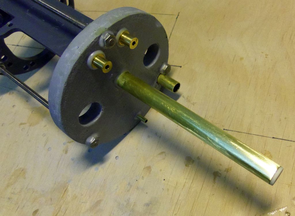
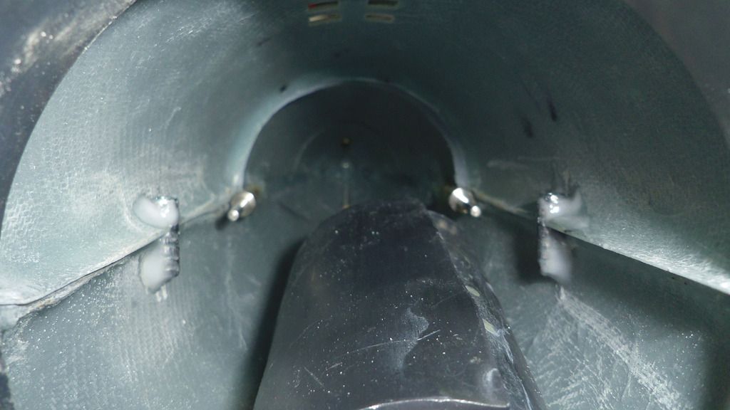
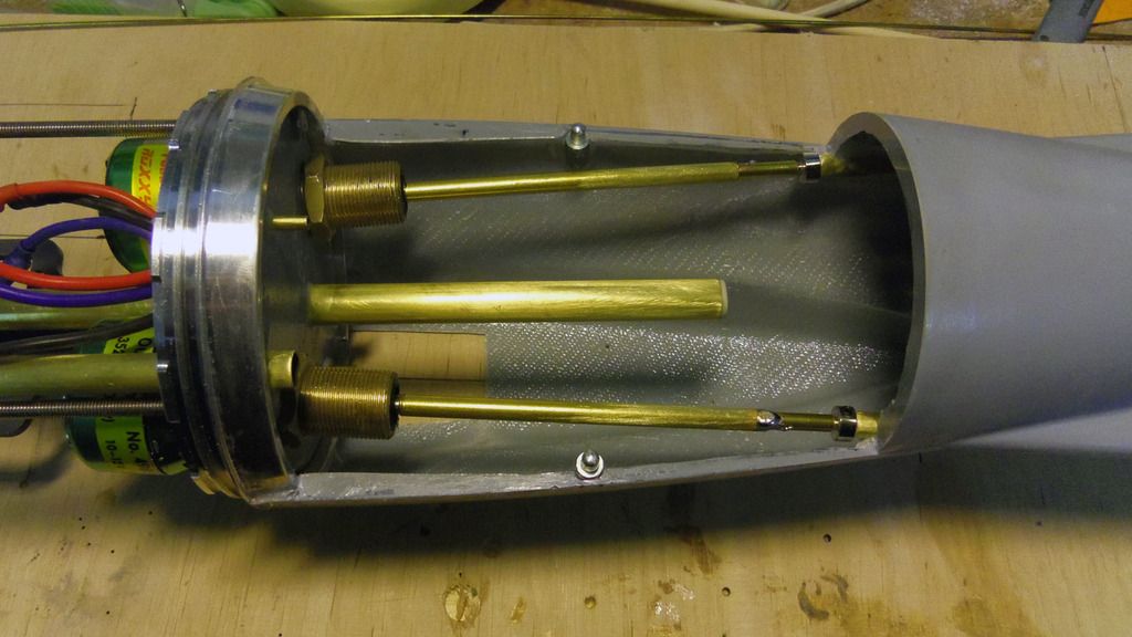
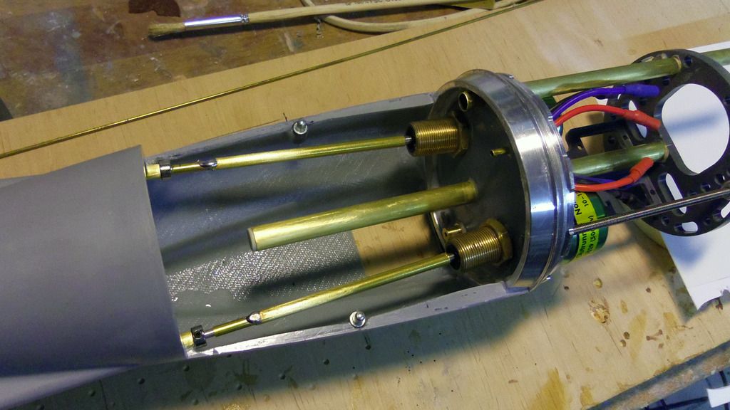
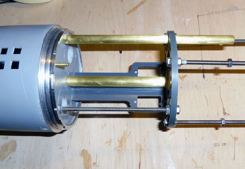
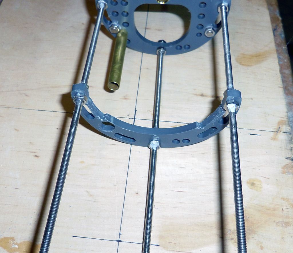
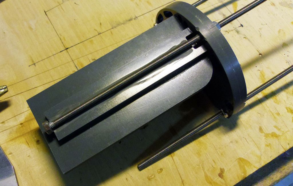
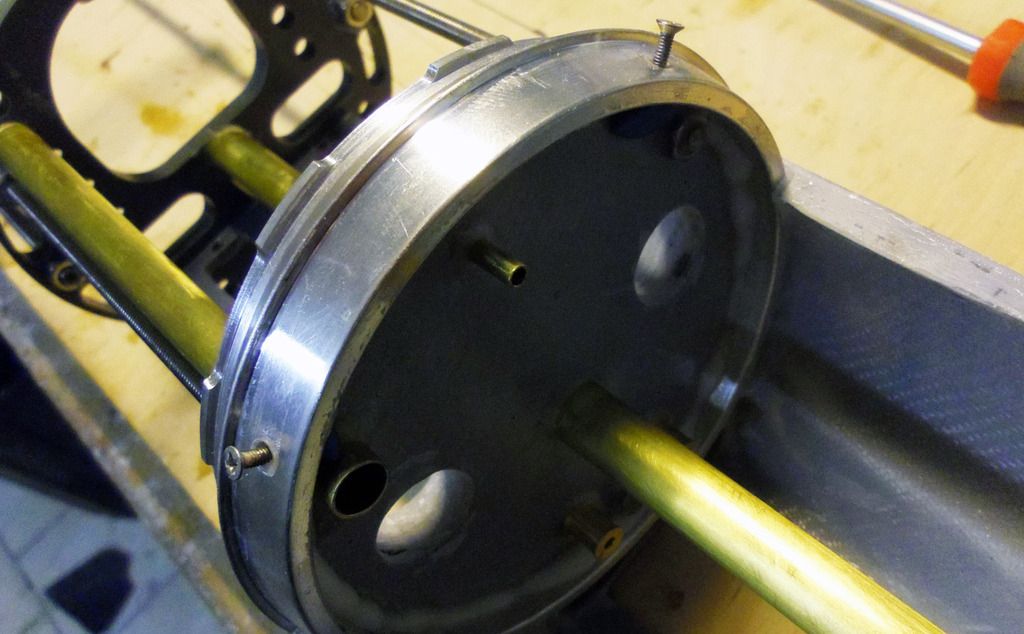
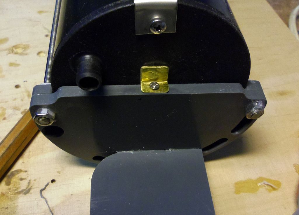
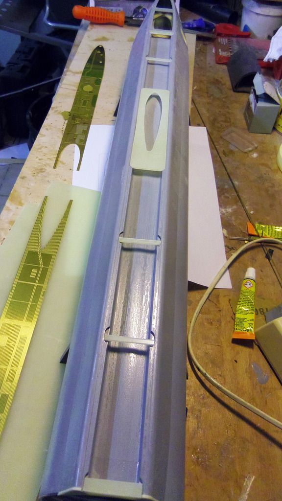
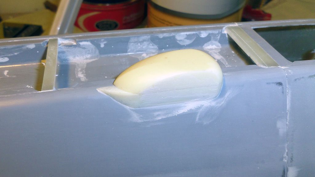
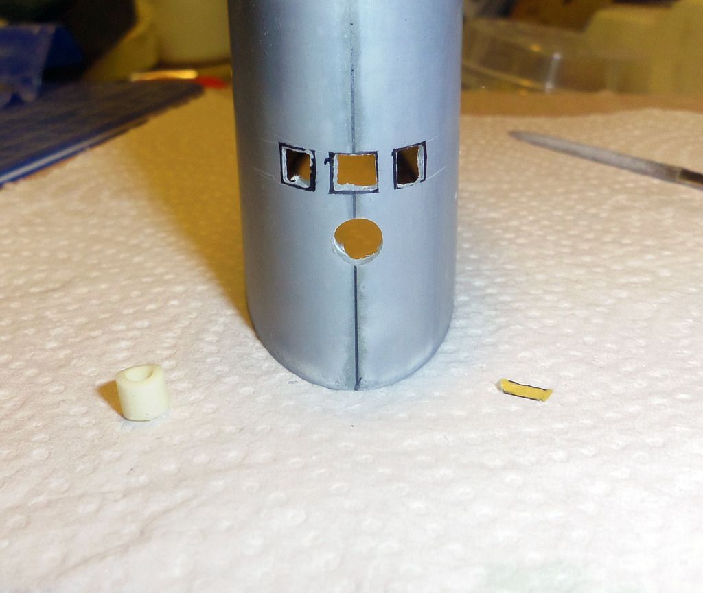
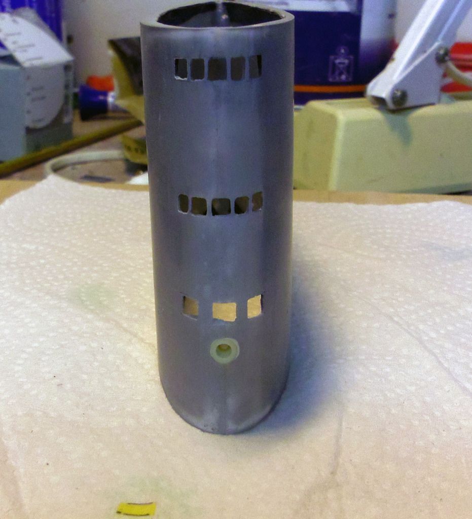
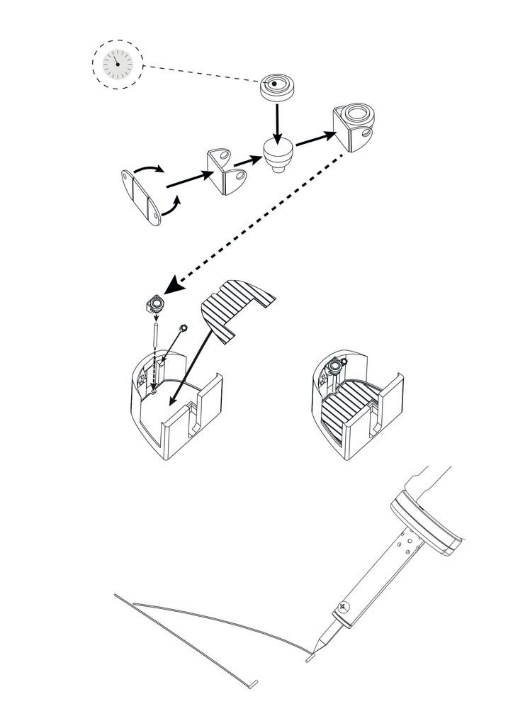
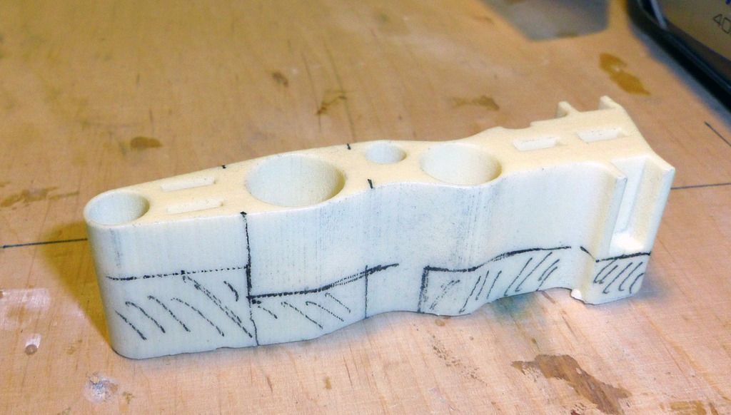
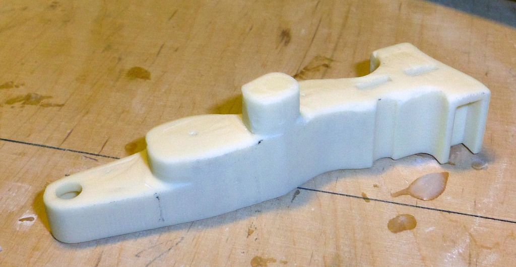
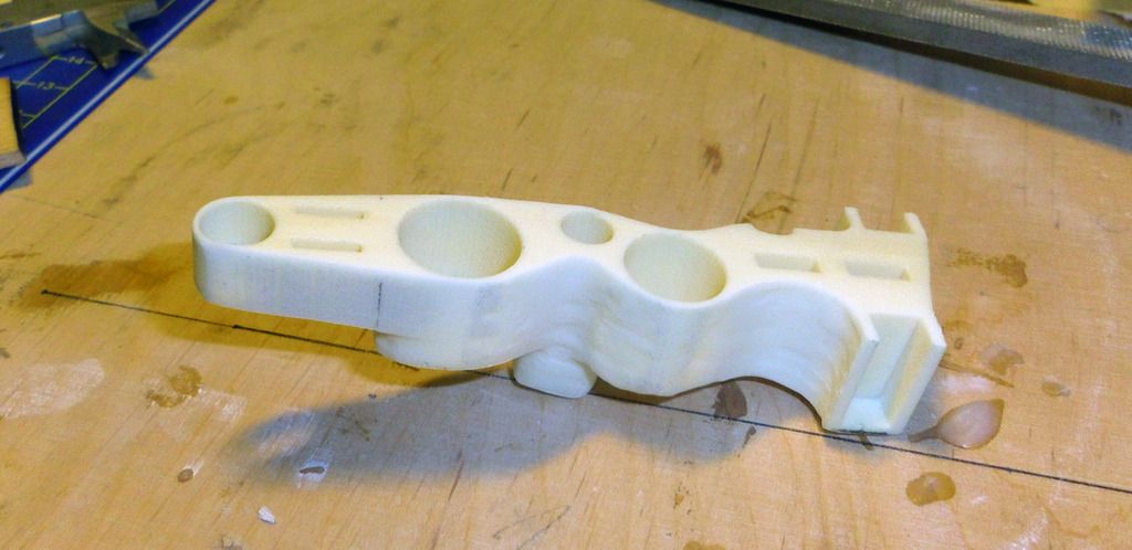
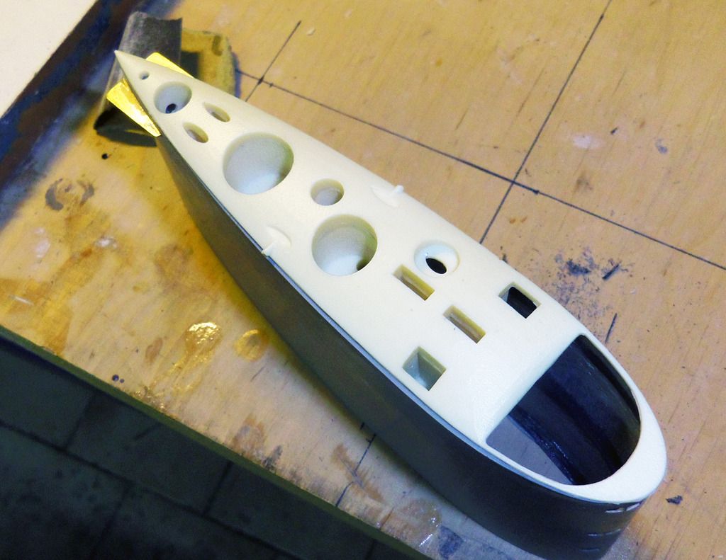
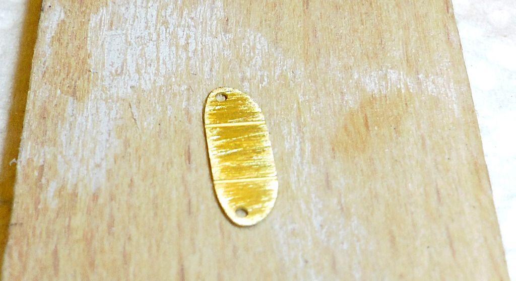
    To finalize the first interior section, the tube fort he thread rod oft he piston tank is glued shut with the resin pug. In addition the connectors fort he rubber bellows fort he push rods (Engel-Modellbau) are glued into position:


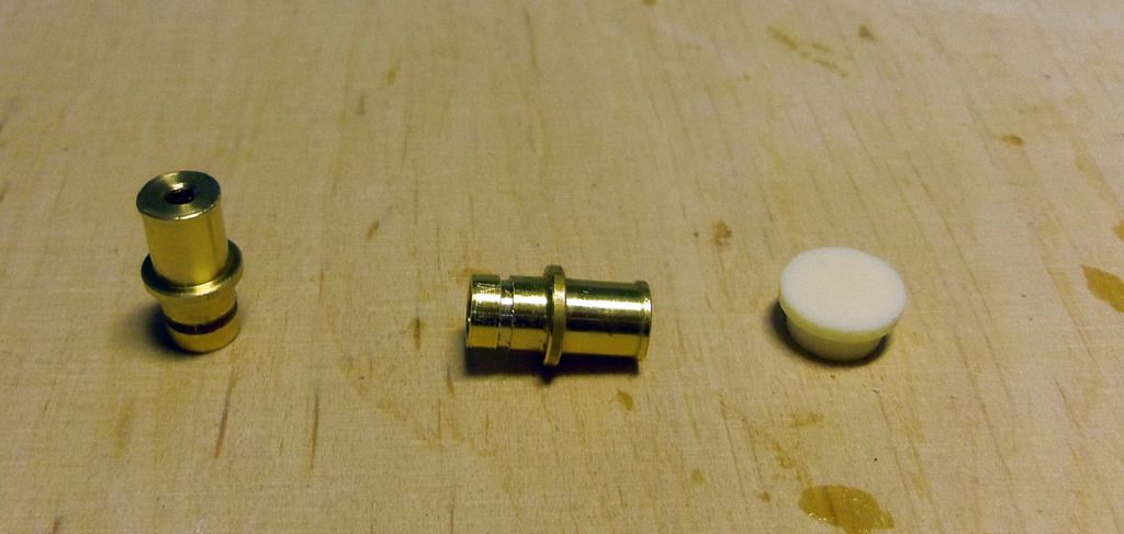
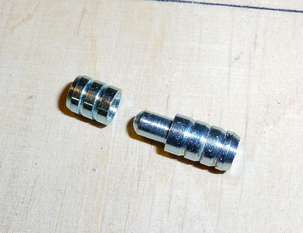
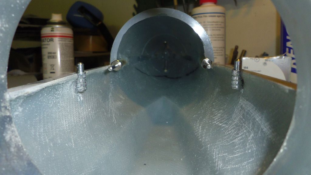
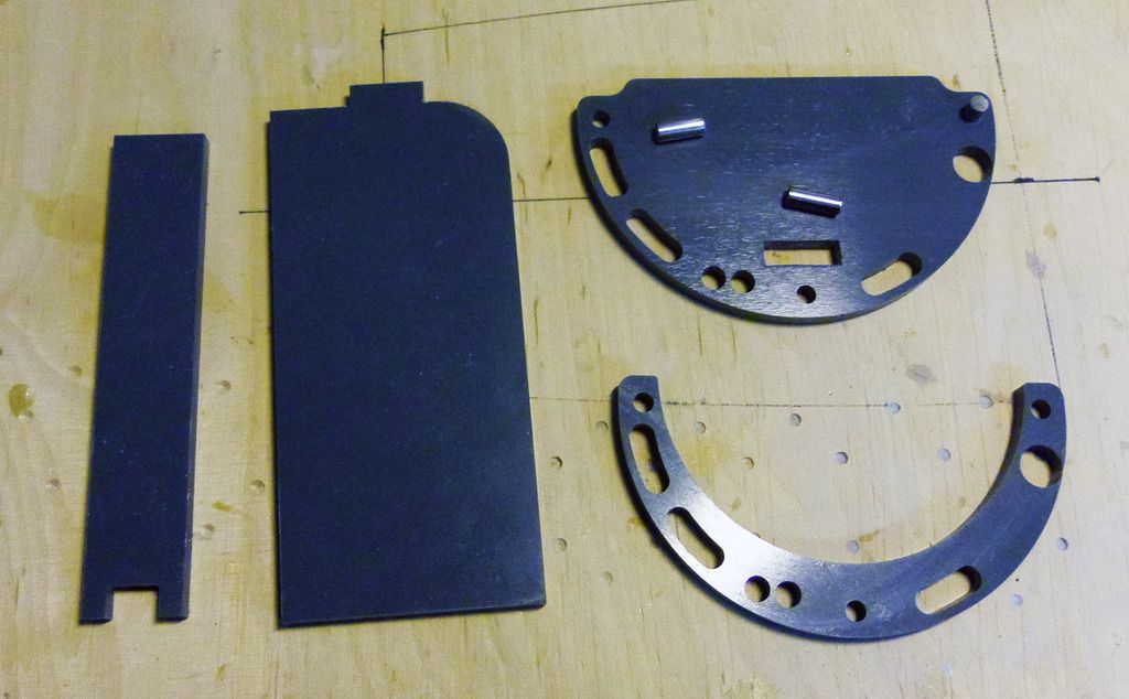
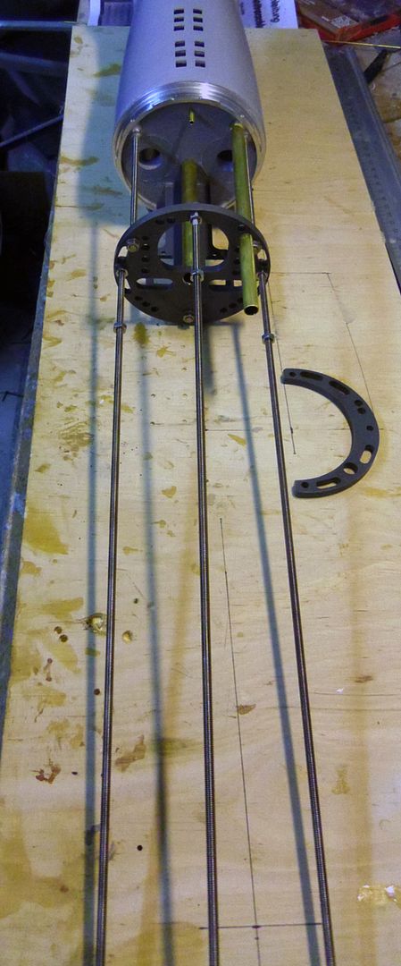
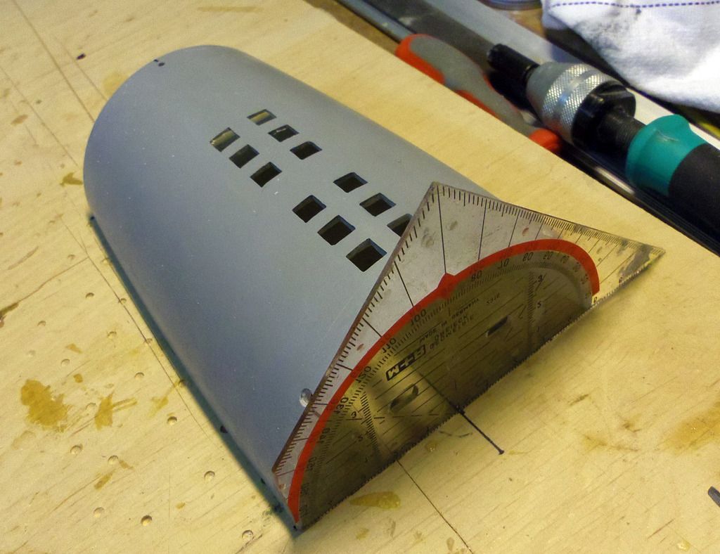
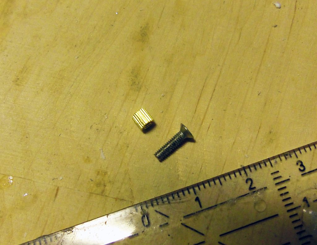
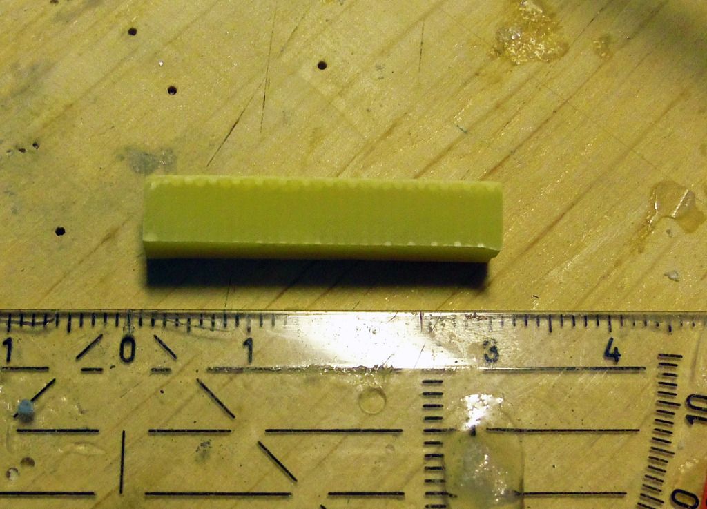
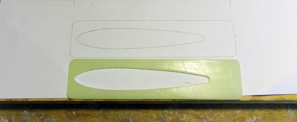
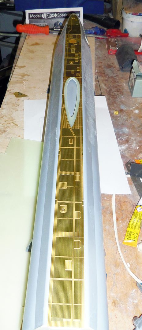
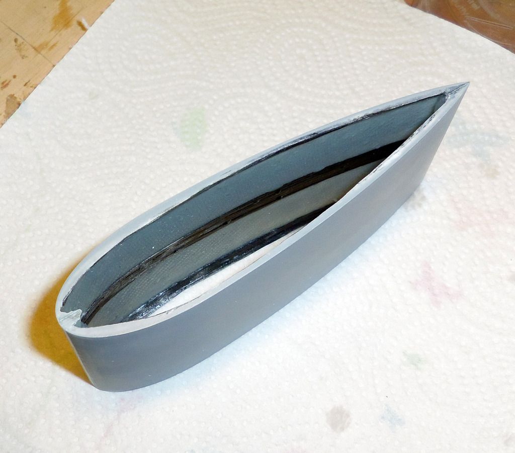
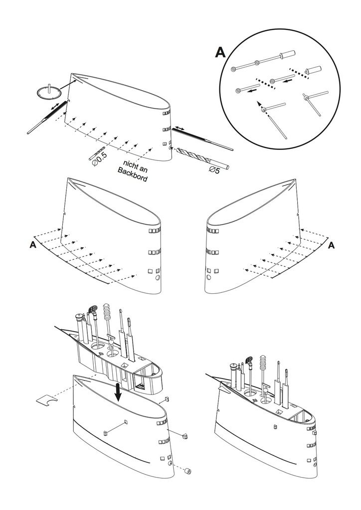
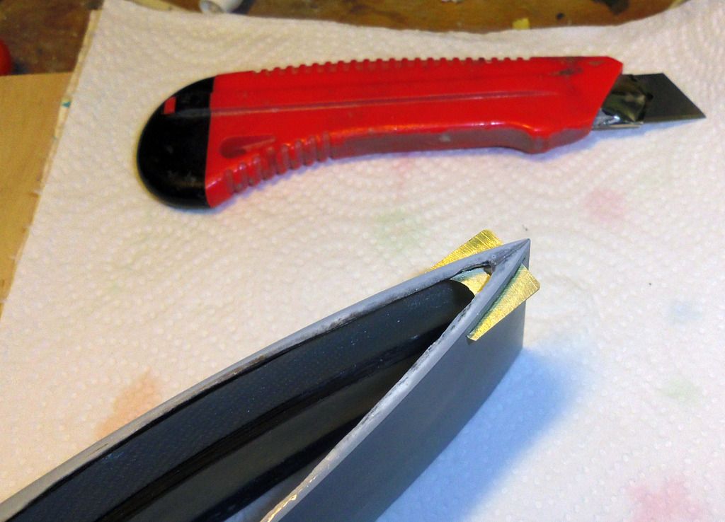
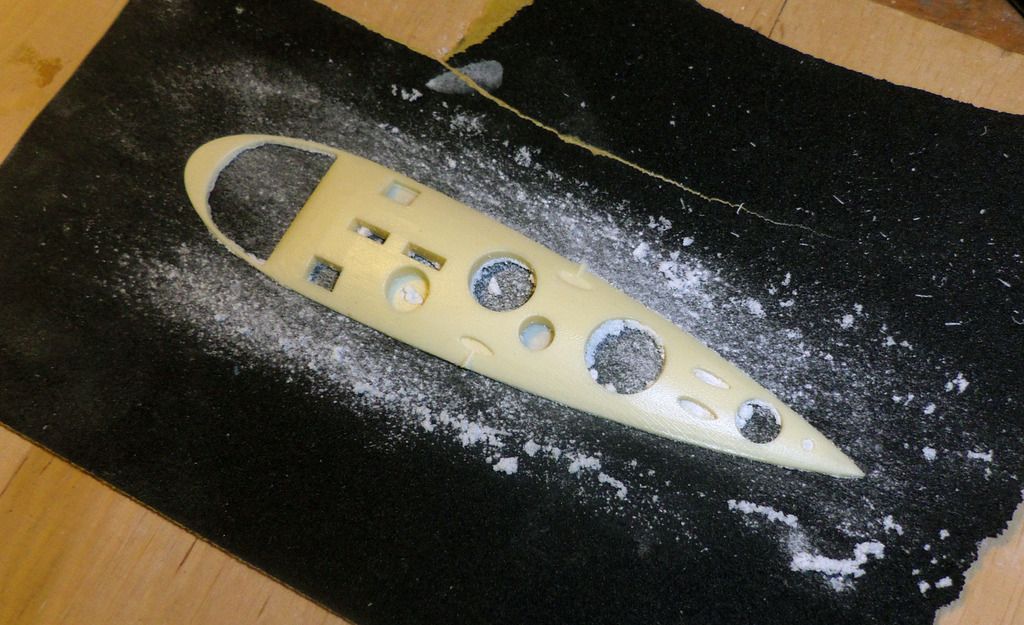
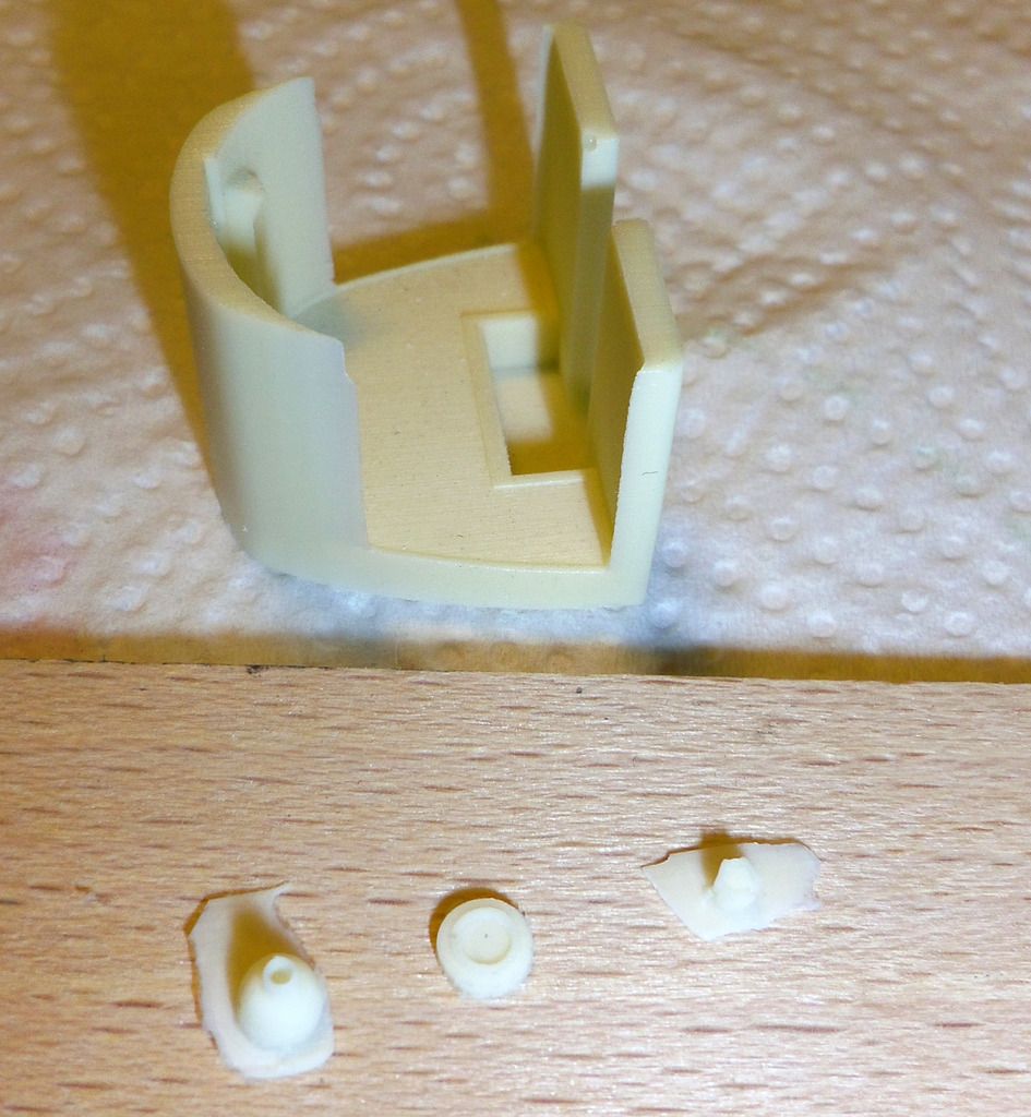
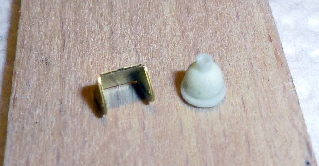
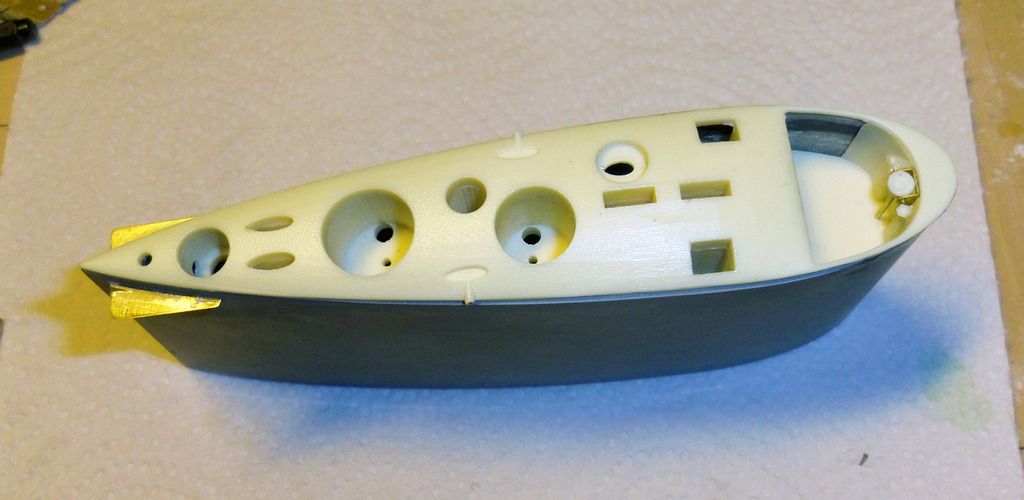
    Then the plug-in mounts of the service hatch are installed. I use aluminum pins and sockets originally intended to be used for moulds, but brass pins and sockets are equally suited:


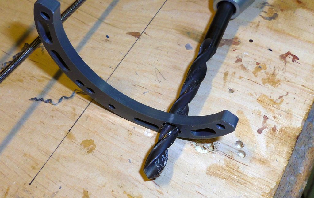
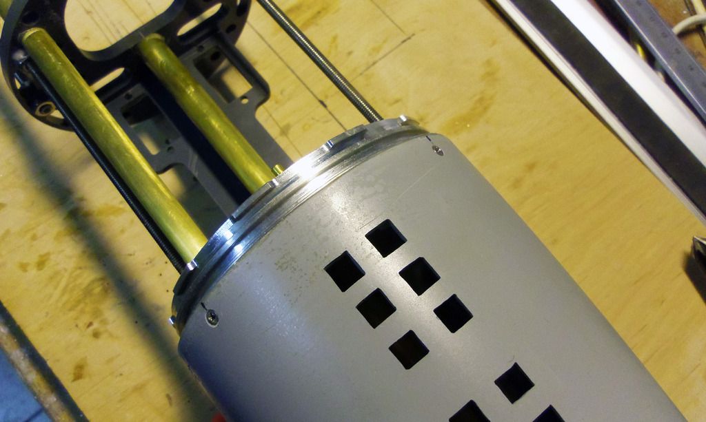
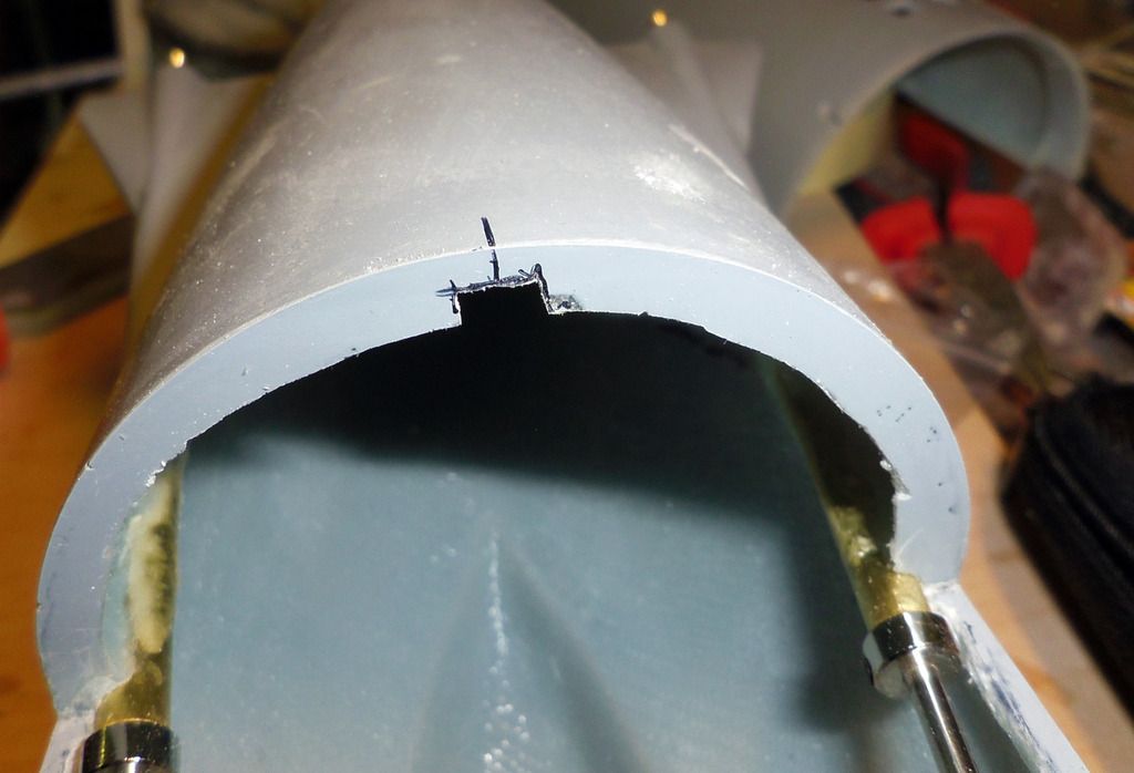
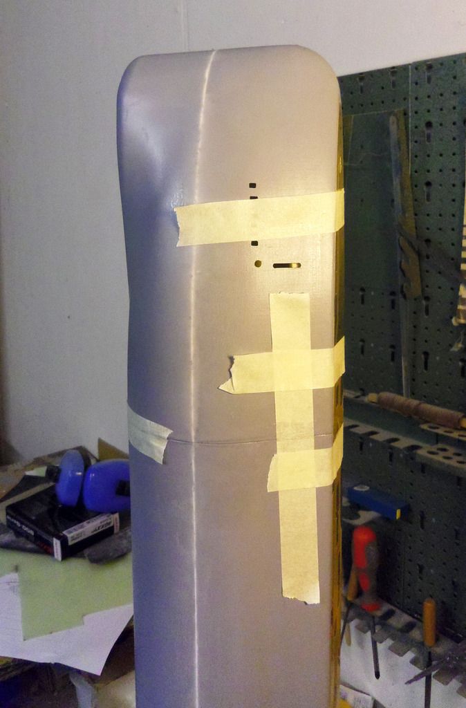
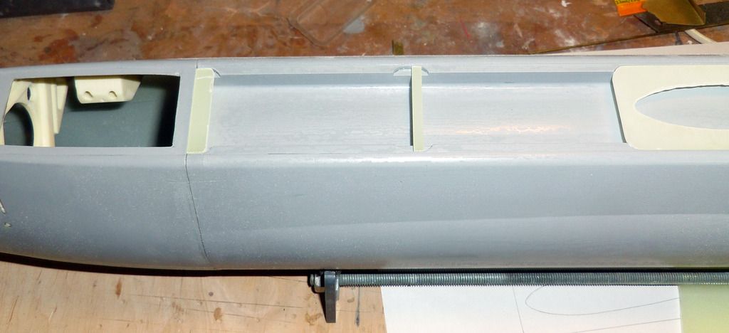
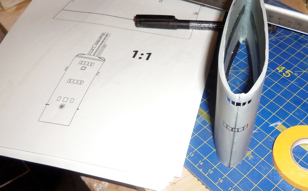
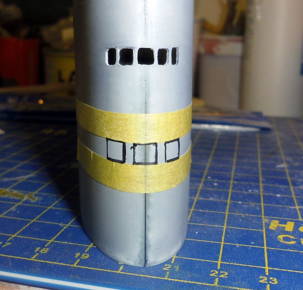
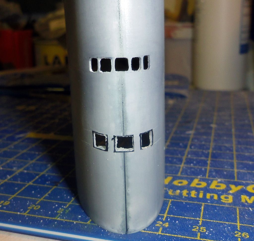
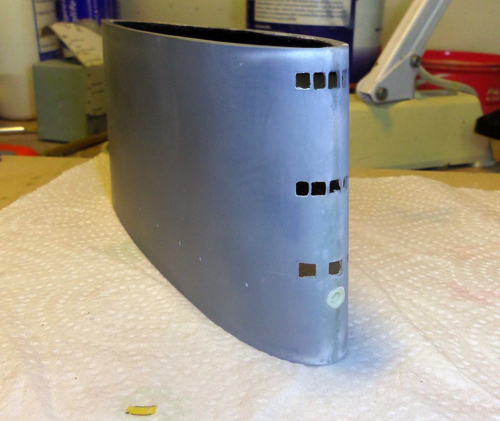
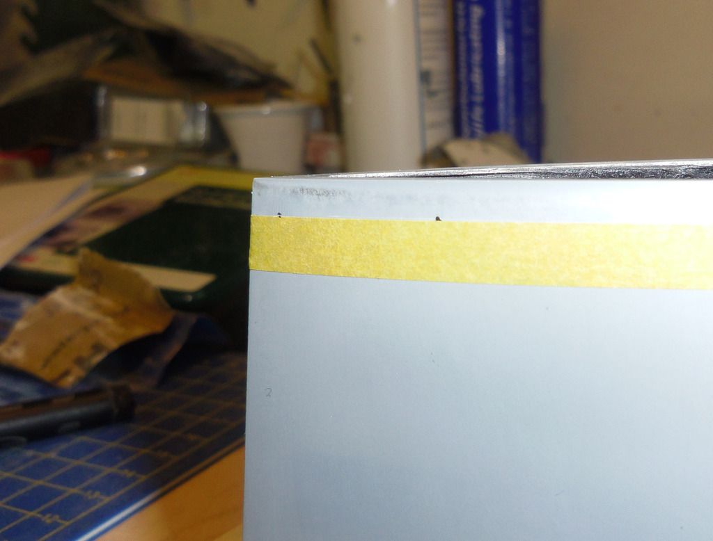
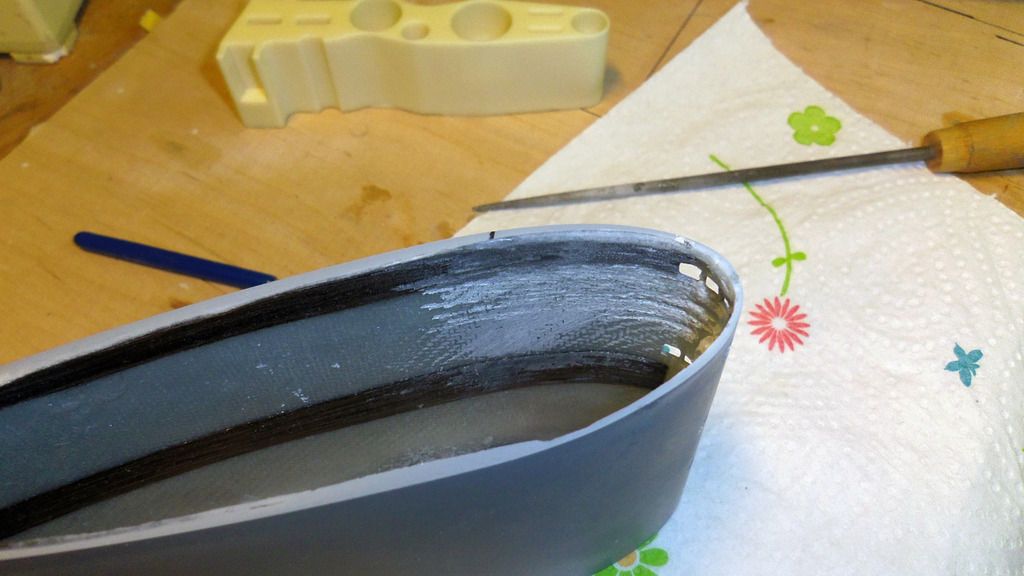
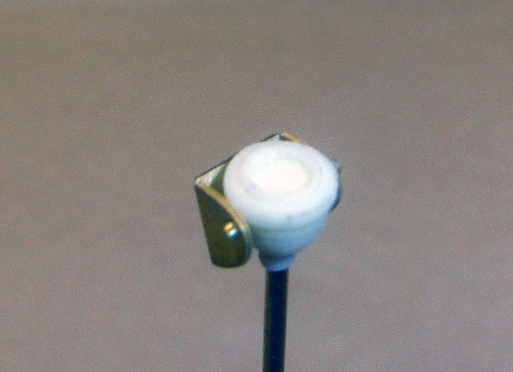
    The position of the pins is marked on the edge of the stern section, drilled and filed. The pins are the preliminarily fixed using superglue:


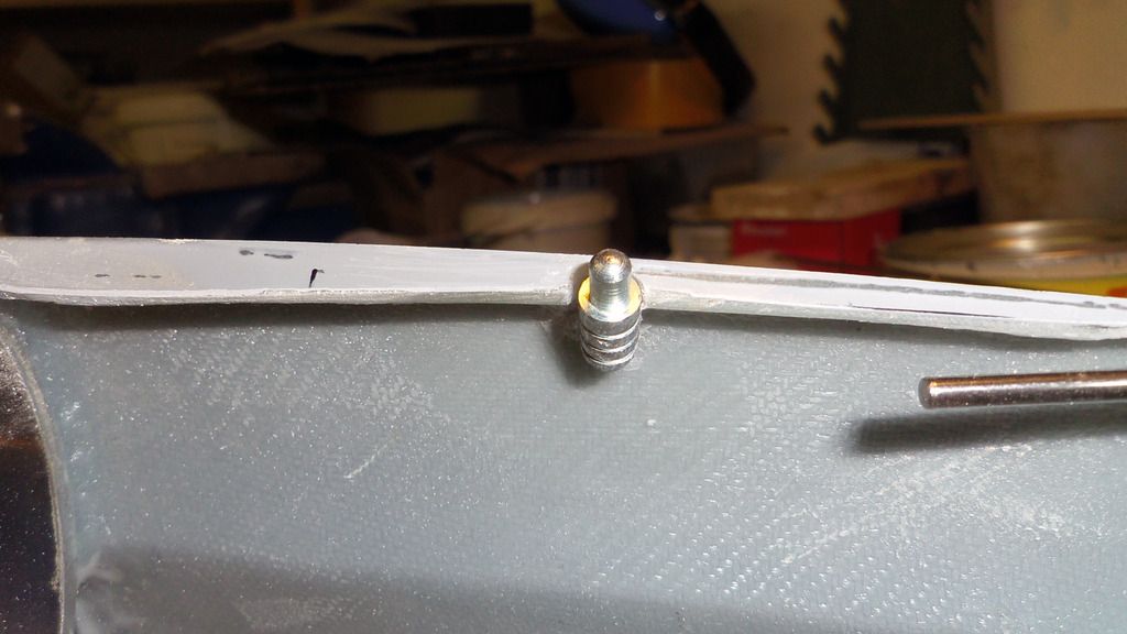
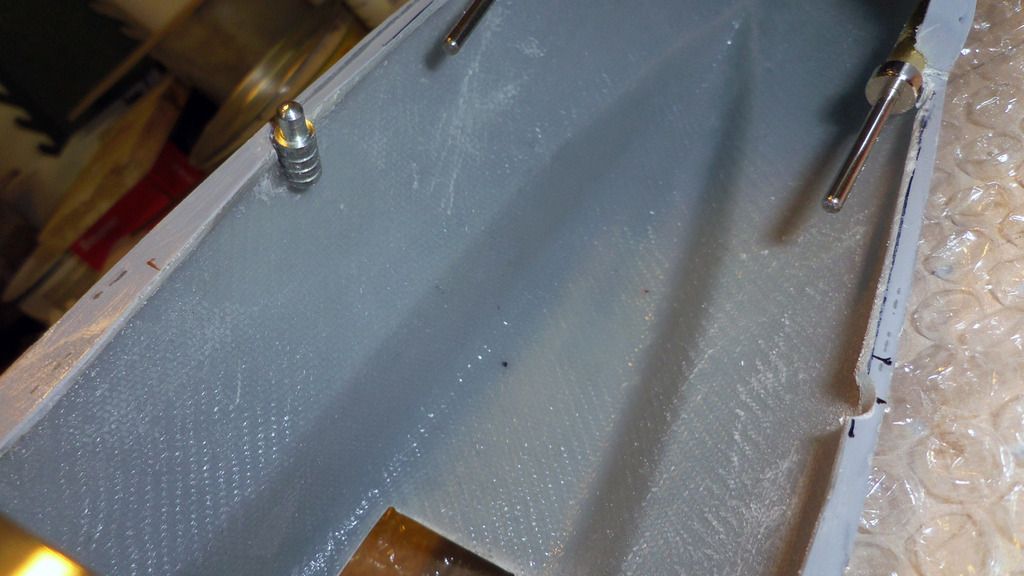
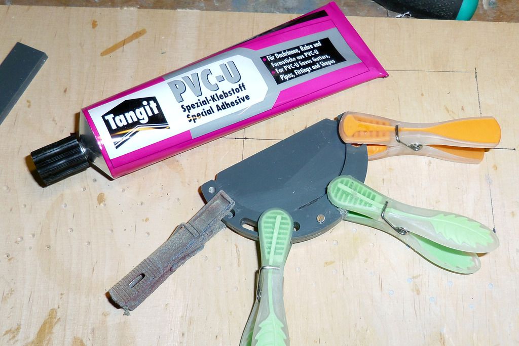
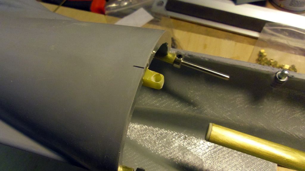
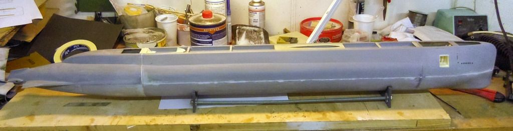
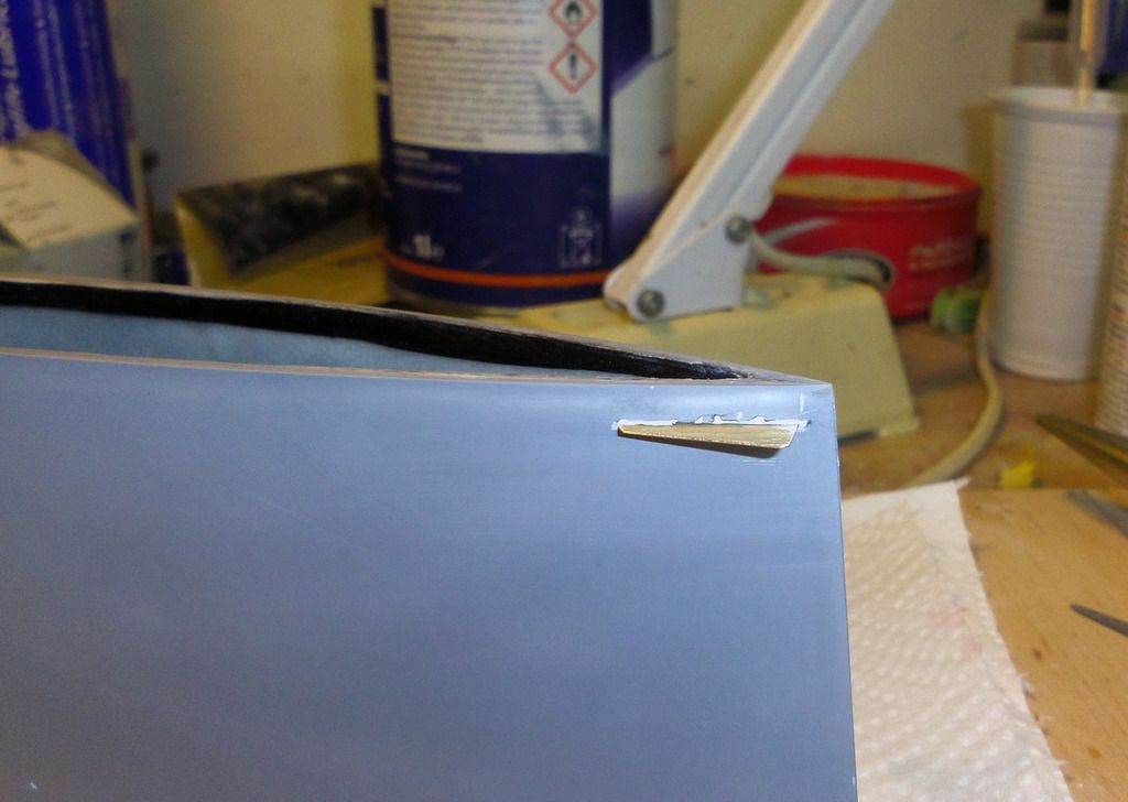
    Then the pins are finally glued into place using again epoxy:

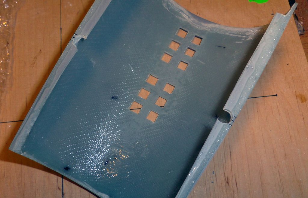
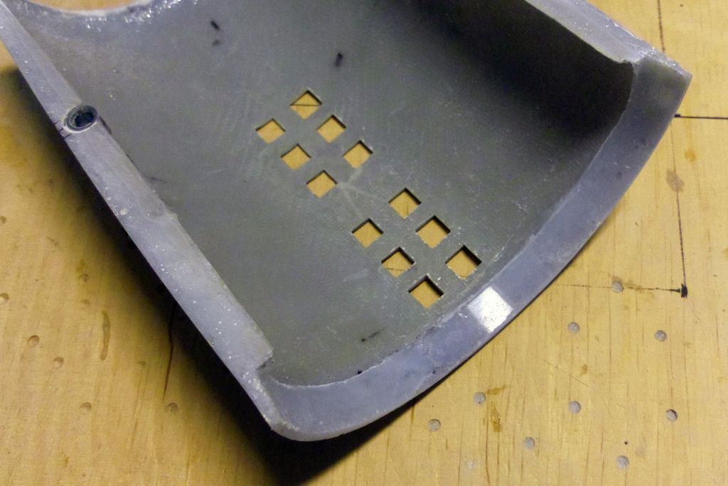
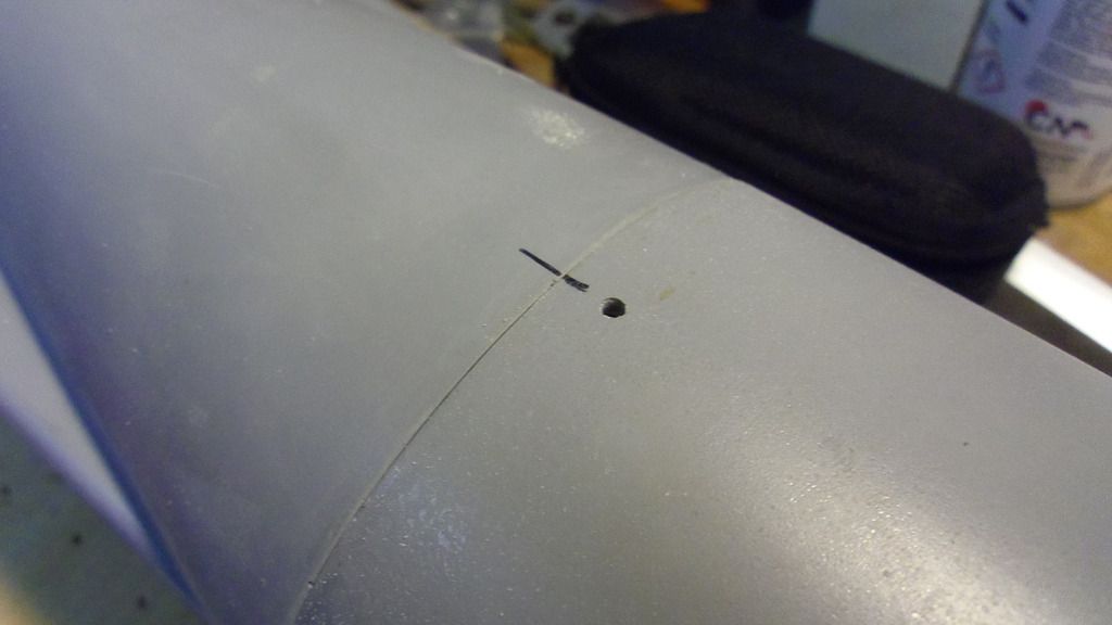
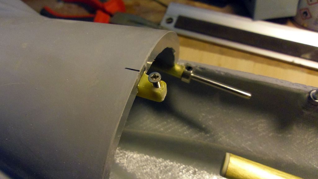
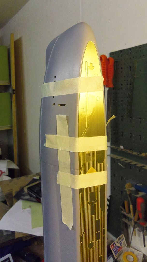
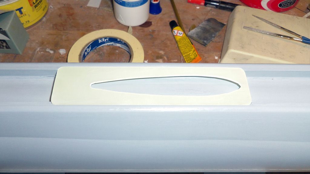
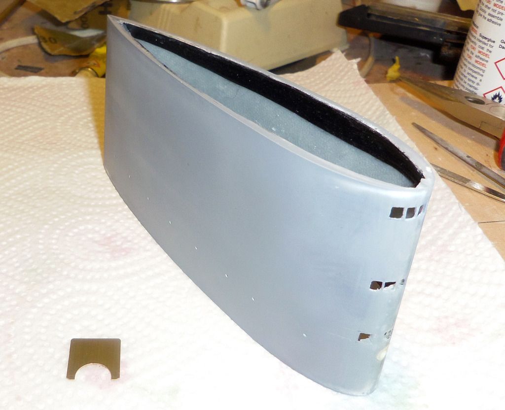
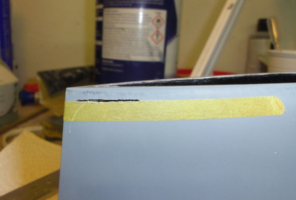
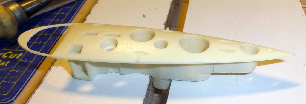
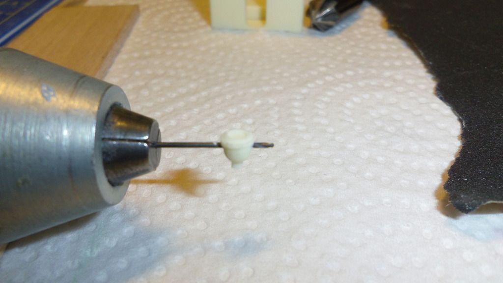
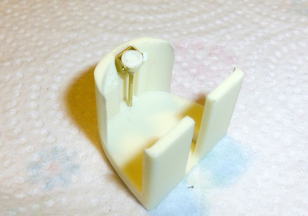
    The positions for the sockets are marked on the hatch, drilled and filed:


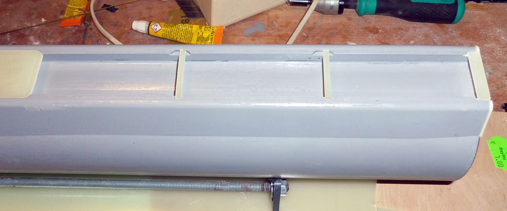
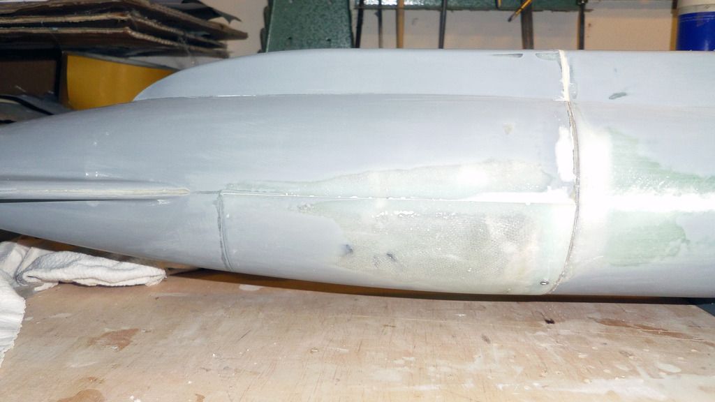
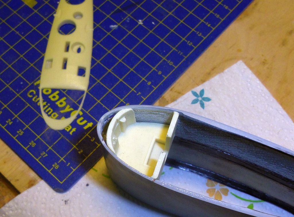
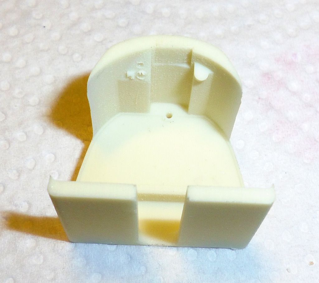
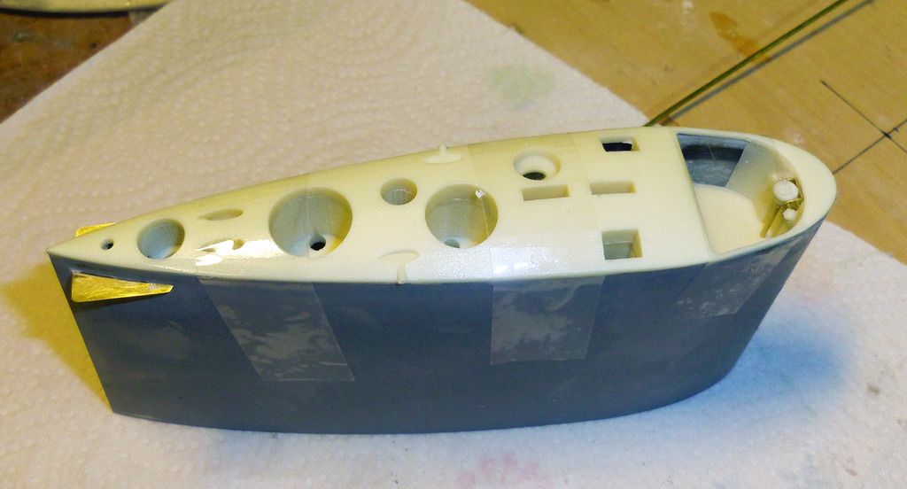
    The pins are treated with a release agent (Polyvinyl alcohol), the sockets put on, the hatch installed and fixed with adhesive tape:


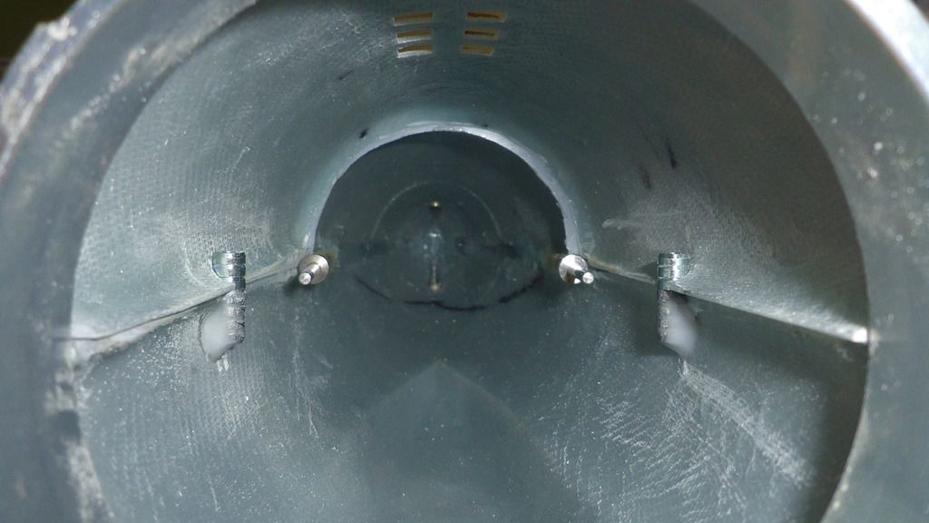
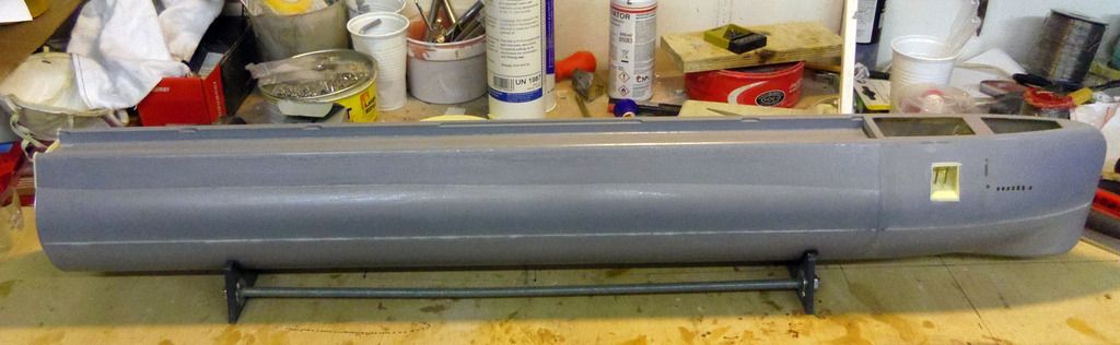
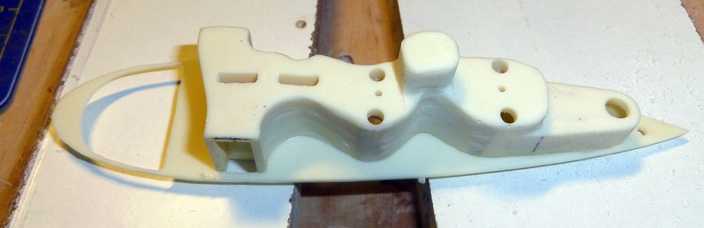
    Then the sockets are glued into place using epoxy:


    Comment

    • DrSchmidt
      Captain
      • Apr 2014
      • 919

      #17
      To fit the service hatch tot he bayonet ring, the ring and the adjacent GRP parts have been treated with release agent. Then thickened resin was added to the inner rim of the hatch and everything put together. Through the still open bayonet ring excess resin can be removed. When everything is cured, disassemble, clean the seams and the fit is done:


      The battery support is made of four milled PVC parts. Again, remove the milling radius at the positions where parts are put together. To assemble the two half bulkheads, four 4 mm diameter studs were made, that help to perfectly align the two bulkheads. Assemble using PVC glue:


      The battery support board is glued to the bulkhead in a right angle:


      Comment

      • DrSchmidt
        Captain
        • Apr 2014
        • 919

        #18
        After fitting the service hatch, the first section of the inner structure can be glued into the stern section. In particular, the motor bulkhead has to be glued into the inner ring of the bayonet catch. Actually that is simpler than it might seem. The watertight motor feedthroughs are put into the holes of the motor bulkhead and locked. I use my custom-made ones from the prototype:


        Because of the v-shape of the motor bulkhead and the position of the motors, the propeller shafts and the motor shafts are perfectly collinear when the bulkhead is correctly positioned. To reach this alignment, I fabricated two auxiliary tools. They are basically 4 mm brass tubes put into 5 mm brass tubes. The tubes are glued or soldered together. The 4 mm tube is put onto the 3 mm propeller shaft, then the 4 mm motor shafts are put into the 5 mm end of the tool until everything sits loosely. The motor bulkhead is in the right position.


        The inner ring of the bayonet catch and the motor bulkhead are sanded with coarse sandpaper and then cleaned with acetone. A generous amount of extreme-strength epoxy is put into the middle of the inner ring. Then put the motor bulkhead into the ring using the auxiliary tools. Check if everything is positioned correctly, then let thoroughly cure everything.


        Comment

        • greenman407
          Admiral
          • Feb 2009
          • 7530

          #19
          Brushless outrunner motors, with no gearbox. Nice
          IT TAKES GREAT INTELLIGENCE TO FAKE SUCH STUPIDITY!

          Comment

          • DrSchmidt
            Captain
            • Apr 2014
            • 919

            #20
            Saves allot of space.....but you need two speed controllers.

            Comment

            • DrSchmidt
              Captain
              • Apr 2014
              • 919

              #21
              Next is the second part of the inner structure. Three M4 stainless steel thread rods are screwed into the last bulkhead of the first section. The nuts are secured using superglue:


              In the first support bulkhead for the piston tank the hole for the water hose is drilled wider to 9 mm diameter:


              Then the support bulkhead is secured in the right position using M4 stainless steel nuts, which are again secured using superglue. It is important to adjust a constant distance between the bulkheads to ensure that the support and the thread roads are correctly positioned and aligned:


              In the forward battery support bulkhead, recesses for the metal bends and their supporting screws are machined. The bulkhead has to fit tight against the bulkhead:


              In the first support bulkhead recesses for the metal bands of the piston tank are machined as well:


              The battery support bulkhead is secured in the correct position using M4 nuts, which are again secured suing superglue:


              With this, the inner structure is basically done and the position of the piston tank well defined:


              Comment

              • DrSchmidt
                Captain
                • Apr 2014
                • 919

                #22
                The fastening of the service hatch is done with three M2 screws. The position of the screws are marked on the hatch ( 2 x under 45° on the bow side and one in the middle on the stern side). The 2 mm holes are drilled.


                The hatch is attached and the bow holes transferred into the bayonet ring. The holes in the ring are widened to 3 mm diameter and M2 brass thread insets are glued into them. For this, the screws are first treated with release wax:


                The thread insets are available from china in 20 piece packaged for 3€ on eBay. The bow fixture is done:


                The stern position of the hole is transferred onto the sterns section:


                A support strut is cut from 5 mm GRP plate material:


                The strut is fit into the stern section:


                The support I glued into place, the 2 mm hole in the hatch is transferred into the strut, widened to 3 mm diameter and a thread inset glued into it:


                With that, the stern fixture of the hatch is done, too:


                Comment

                • DrSchmidt
                  Captain
                  • Apr 2014
                  • 919

                  #23
                  To secure the piston tank a bracket with a 2 mm hole is fabricated form 1 mm brass sheet. With the tank in place, the bracket is fixed using superglue:


                  The position of the 2 mm hole is transferred onto the battery support, widened to 3 mm and again a thread inset installed. In the soft PVC it can be punched into place.


                  With a M2 screw, the tank now can be secured:


                  Comment

                  • DrSchmidt
                    Captain
                    • Apr 2014
                    • 919

                    #24
                    Next, the bow section is glued to the pressure-tight main hull. Sand and clean the adherent and fix both parts using high-strength epoxy. The bow deck is used to align the two sections but mustn’t be glued yet.


                    With that the main hull is complete:


                    To support the photo-etched deck and to mount the sail, struts, fabricated from 2 mm GRP sheet material, are fabricated and glued into the associated recesses in the main hull:


                    Again remove epoxy residues using a soft cloth and acetone. The deck is put onto the hull to check for the correct position f the struts but mustn’t be glued yet.


                    Side remark:

                    The photo-etched deck is best removed from its sheet using a Dremel drill with a small cutting disk. Carefully clean the edges using fine grade sandpaper.

                    Comment

                    • DrSchmidt
                      Captain
                      • Apr 2014
                      • 919

                      #25
                      Put together it starts looking like a boat. Now it gets dirty: Grinding, filling seams and gaps, again grinding. What one invests here in time, care and sweat will pay off twice when the first layer of primer is applied.


                      Comment

                      • DrSchmidt
                        Captain
                        • Apr 2014
                        • 919

                        #26
                        A few hours later: The whole boat is wet sanded and where necessary, the contours are corrected using 2-komponent polyester putty (usually used for cars). To get the seam of the service hatch as narrow as possible, the hatch is treated with release agent (PVA), putty is applied to the cut for the hatch, and then the hatch is pressed into the soft putty and fixed using the M2 screws. Wet sanding (400 grade sandpaper) and the fit is close to being seamless.


                        The final part that goes onto the hull is the sonar dome. It is made of two cast PU resin parts.


                        Clean both parts and glue them together (superglue):


                        The deck is put onto the hull, adjusted and then the sonar dome is glued to the hull where its position is marked on the deck. Don’t fix the deck yet.


                        Fill the seam, sand it, done:


                        Next the hull can receive its base coat.


                        The sail (GRP) is cleaned and sanded with 600 grade sandpaper before further assembly steps can be started:


                        Comment

                        • DrSchmidt
                          Captain
                          • Apr 2014
                          • 919

                          #27
                          First the viewports in the sail have to be defined. Nautilus had three levels of these viewports and at 1:87 scale they are actually only 3 x 4 mm large and are separated by only 0.5 mm minimum. The easy approach would be to just paint them on. I decided to cut them out. Mark, drill, file:


                          For the marking masking tape is a good choice as it can easily be corrected until everything is in the right position:


                          Centrally under the lowest viewport level a resin detail is fit into a 5 mm diameter drilling. Glue it into place, filling, sanding, done:


                          Comment

                          • DrSchmidt
                            Captain
                            • Apr 2014
                            • 919

                            #28
                            On it goes with the sail, mast support and bridge assembly:


                            On the upper rear edge of the sail the fin (photo etched part) is inserted:


                            The position is marked with masking band end edding and a slit is cut free using a 0,3 mm drill:


                            The fin is glued into position, the seams filled and sanded flush:


                            In the area of the bridge the inner edge of the sail has to be removed using Drehmel tool and diamond files. The bridge has to sit flush.


                            Comment

                            • DrSchmidt
                              Captain
                              • Apr 2014
                              • 919

                              #29
                              The mast support is a big resin cast part. To reduce its volume, not needed sections are marked and removed using saw and files.


                              The underside of the sail deck is sanded planar and the seams are cleaned:


                              The mast support is glued to the underside of the sail deck. Watch for exact positioning:


                              3 mm diameter vent holes are then drilled into the mast support.


                              Test fit and set back the inner edge of the sail if needed:


                              The bridge is a resin cast part. It still need compass repeater and rudder indicator, which are also resin cast parts.


                              The compass repeater is made of two parts – housing and lid. Both are sanded planar and cleaned. Glue them together using superglue and drill a 0,5 mm diameter hole horizontally through the housing:


                              Drill a 1 mm diameter hole in the marked position of the bridge deck:


                              Comment

                              • DrSchmidt
                                Captain
                                • Apr 2014
                                • 919

                                #30
                                The bracket for the compass repeater is a photo-etched part. Cut free, clean the seams and sand it using 600-grade sandpaper. The bend the wings into right angles using tweezers:


                                Put everything together with a 0,5 mm brass bolt and fix it with superglue:


                                Put the compass repeater it into the bridge using a 1 mm brass wire and fix with superglue:


                                The rudder indicator is again sanded pkanar and glued into position using superglue.
                                Then the bridge assembly is glue to the underside of the sail deck. Test fit the whole assembly into the sail and make adjustments where necessary.


                                When everything fits, glue the deck assembly to the top of the ail using epoxy:


                                Comment

                                Working...