SS-581 Blueback

Collapse
X
 
  • Time
  • Show
Clear All
new posts
  • SSN687
    Lieutenant Commander
    • Nov 2015
    • 119

    SS-581 Blueback

    It’s here, well it’s been here. I refused to open it until I got most of the consumables, instructions page 3, to build it. I have checked the parts and they all there except the 3 washers on page 2 bottom left hand corner of the instructions. No problem, I pretty sure I can find replacements for these 3 washers.
    The biggest new item that I got and it showed up 30 March was a Paasche TS airbrush. I’m off the body shop Tuesday (5 April). The body shop that painted my 66 Mustang is going to let me use his air system and paint booth to start learning how to use the airbrush. The shop owner has saved a bunch of card board boxes to practice making dots and connect them. I have a quart of the Nason gray primer to start out using but a girl in the local helmet painting shop said that I should use Createx paint, it’s cheaper (cost) to use for learning. I have the booth all day Tuesday so who knows what will happen by Tuesday evening.

    1 April 2016 Friday
    I spent a great deal of time figuring out which fairing and was associated with what piece of metal antenna. A picture in the instructions of both sides of the completed sail with all fairings with metal antenna inserted or a top view of the Blueback drawing would have helped. The top view would have helped identifying the openings in the top half of the hull.
    I can figure it flipping back and forth through the instructions and looking at HardRock’s Blueback build and Start Saving Your Pennies, but there is a guber 1 1/2 “ from the tail end on the upper half fiberglass hull. Is this the last hole with red putty on it as pictured on the Instruction page 23 on the upper hull a vent also?

    2 April 2016 Saturday
    Today is cleaning and sanded the hull and tail sections as per the instructions, deburred the metal parts and they are ready for the ferric chloride soaking.

    4 April 2016 Monday
    Ferric chloride soaking/cleaning metal parts for primer tomorrow. Cleaned and sanded the sail, fairings, and tail piece
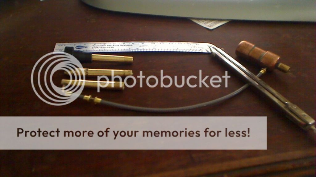
    Had to make a quick disconnect/pressure regulator connection for the body shop air header. The body shop’s air header is at 90 to 95 psi and I'm going to need 10 to 40 psi. I’m not sure what the helmet shop would have charged me to primer the Blueback, but they were going to charge me $200 to repaint my 1966 South Carolina license plate which is my permanent plate now. So if I teach myself to use the airbrush gun tomorrow, this winter I can sandblast and repaint the plate myself. Already the airbrush is saving me money, just have learn how to justify these new toys.

    5 April 2016 Tuesday
    Packed everything I need to learn how to use the new airbrush and primer the Blueback, off to the body shop. Spent 6 hours in the paint booth at the body shop Tuesday. Lots and lots of various size dots and connecting them. After a couple of hours of this I decided I was ready to start priming the parts. First paint pass on the hull, I was to close. It looked really bad and thought I had screwed the pooch. The shop owner was in the booth and showed me how to fix it. Wiped the bad section down with thinner, let it dry, life was good again and was able to finish primer coat. Took some picture of it in the paint booth. Don't think that the Sistine Chapel will be calling me to help do any repair work there.

    6 April 2016 Wednesday
    Unpacked everything I took to the body shop. The body shop owner can get the same primer I used and save me any shipping cost. Need to look on site for black and red lead colors and get the body shop to order them for me.

    7 April 2016 Thursday
    Updated build log going to try to upload to site. Found the black and red lead colors specified in the Start Saving your pennies, post #44. Still need to find how to camouflage the fairings. I’m at starting the tail cone, instructions bottom of page 11.
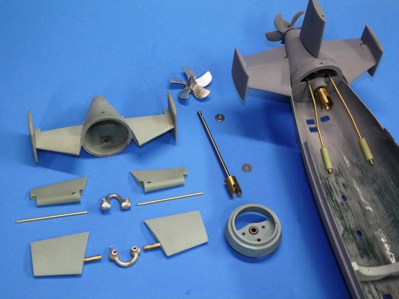
    Checking parts


    Before Primer


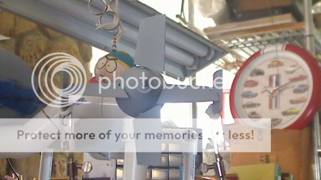
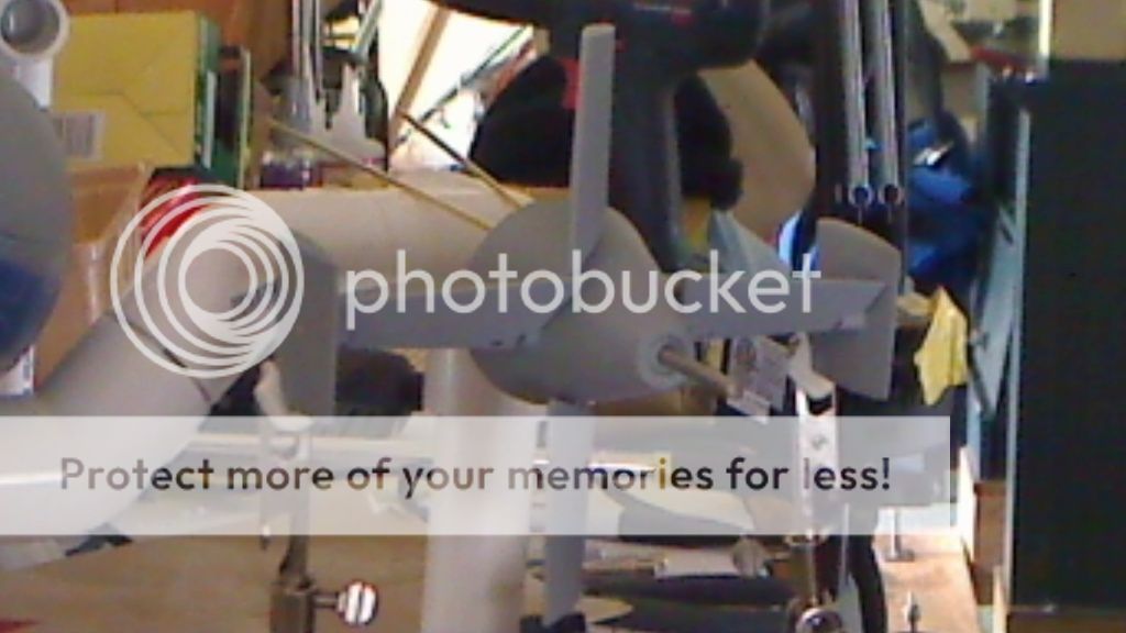
    In the paint booth after primer


  • SSN687
    Lieutenant Commander
    • Nov 2015
    • 119

    #2
    I sent you message last Friday, but I guess you don't check them. I'm working on the Blueback that I purchased from you. I just opened the SD that I received from you last month with the Blueback. I was looking ahead on my Blueback build. From page 24 of the instructions, the snorkel assembly and a small screw both items circled in attached picture or in the photobucket picture labeled missing parts, are missing from the SD. You told me to contact you about adding an emergency blow system to the SD after I received it also.
    Thank you
    Ernie McElroy
    (SSN687)


    Last edited by SSN687; 04-11-2016, 04:22 PM.

    Comment

    • SSN687
      Lieutenant Commander
      • Nov 2015
      • 119

      #3
      During the set up of the tail section, the stern planes and rudder have enough movement to hit each other. Have I missed something in the set up or just limit the stern planes up and down movement as not to interfere with the full throw of the rudder?


      Comment

      • SSN687
        Lieutenant Commander
        • Nov 2015
        • 119

        #4
        rudder and stern planes hitting other side

        Comment

        • He Who Shall Not Be Named
          Moderator
          • Aug 2008
          • 12253

          #5
          All control surfaces stall out at about 30-35 degree deflection. That's less than what it takes to slap the stern planes into the rudders. As a practical matter you only want a maximum travel on the stern planes of 20 degrees. You're doing fine!

          Once you have the linkages made up to the SD, the normal servo travel should keep you within those limits, as below:


          M
          Who is John Galt?

          Comment

          • SSN687
            Lieutenant Commander
            • Nov 2015
            • 119

            #6
            I'm getting ready to order some items from McMaster-Carr. I just want to verify some of the threaded sizes in the kit. All the machine screws are 2-56 threads except for the sail screws, some of my measurements have the SS machine screws closer to 4mm x 6mm but the 2-56 threads seem to match each other.
            I'm ordering a 2-56 drill and tap for these.

            The SS set screws my best guess they are 4-40 threads, 1/8" Long.
            I'm ordering a 4-40 drill and tap for the set screws and more set screws.

            The best I can figure is that you use a 1/4 inch 82 degree counter sink.
            I'm ordering that option for a counter sink.

            OK, my ex job on the Russell had me working aft of frame 57, I had rather ask than make another order.

            Is there some trick to getting the control rods connected in the tail section after it has been put together, other than a lot of patients?

            Ernie

            Comment

            • SSN687
              Lieutenant Commander
              • Nov 2015
              • 119

              #7
              I checked the mail box this morning and got your package.
              Thanks
              Ernie

              Comment

              • SSN687
                Lieutenant Commander
                • Nov 2015
                • 119

                #8
                In the attached picture I have drawn a red out lined around the existing the 1/8 inch hole.
                The existing 1/8 inch hole in my SD, but it’s about ¾ inch off the center line of the bottom of the ballast tank. Is it ok to use this hole to align the SD or do I need to drill another hole as per the instructions? If I use this existing hole to align the ballast tank the inlets will cocked.


                Last edited by SSN687; 04-26-2016, 09:09 PM.

                Comment

                • He Who Shall Not Be Named
                  Moderator
                  • Aug 2008
                  • 12253

                  #9
                  No! That hole is to get your hex-wrench in there if you're going to install the emg. blow valve. It's not for the indexing pin. Drill your own indexing pin hole in the bottom of the SD's ballast tank.

                  You people!

                  M
                  Who is John Galt?

                  Comment

                  • SSN687
                    Lieutenant Commander
                    • Nov 2015
                    • 119

                    #10
                    I’m starting on the building/wire the WTC this weekend. The 2.5 inch WTC sure is a small space to get all the electrical items into.

                    Looking ahead, I need to go out and purchase some items today, foam and lead. What is the name brand or type and thickness of buoyant foam that you use to trim the boat?
                    Just to know if I'm in the ball park or not when I start trimming it:
                    About how much foam did you use?
                    About how much lead did you use?

                    Thanks
                    Ernie

                    Comment

                    • SSN687
                      Lieutenant Commander
                      • Nov 2015
                      • 119

                      #11

                      I need some help. I have tried to get my Futaba FP-R1380P receiver (65mm x 36mm x 21mm or 2.53in x 1.4in x 0.83in) that came with my radio, into the 2.5 inch Blueback WTC. I made a new aluminum tray but increased height of the S bend this has my servos outer arm rubbing against the edge of the WTC. Even if I get the new S bend height changed correctly I see another problem. The LPB mounted underneath the aluminum tray long ways is up close to the Futaba receiver, I'm not sure if I’m going to have full travel on the forward bulkhead venting servo. When I click on How to SET UP THE SOMBRA LABS RECEIVER, I get: Sorry - either this article does not exist or you haven't been given permission to view it. This truly has been/is like putting 15 lbs of stuffing in a 10 lbs turkey.

                      I have a Futaba 7CAP/CHP (PCM/PPM selectable ) radio that I had Radio South convert to 75mhz a while back.

                      I have purchased 2 Hitec HS-50 (feather) from the local hobby shop that fit in to the existing green casting on the aluminum tray holder for the 2.5 inch Blueback WTC. The Hitech servo’s are about 1/3 of the torque of the micro servo SKU: BT50 listed on your web page.
                      Servo Output Torque
                      Hitec 0.6 kg.cm (8.4 oz.in) at 4.8Volt
                      BT50 1.6Kg-CM (22oz) at 4.8Volt

                      Two questions:
                      1. Is the SL-8 SKU:SL872 compatible with my radio?
                      2. Do I need to use the BT50 micro servo verses the Hitec HS-50?

                      Thanks
                      Ernie

                      Comment

                      • He Who Shall Not Be Named
                        Moderator
                        • Aug 2008
                        • 12253

                        #12
                        The SL-8, when set-up properly, will talk with your transmitter just fine. Those little servos will do the job, no sweat.

                        M
                        Who is John Galt?

                        Comment

                        • SSN687
                          Lieutenant Commander
                          • Nov 2015
                          • 119

                          #13


                          6 July 2016

                          Well it’s been a long time but I got the 15 lbs. of stuffing into the 5 lbs. turkey. I had to adjust the venting servo stroke and replace because it was chattering, but after replacing it started chattering again. The servo was binding got that fixed now.
                          I had opted to go with a Sombra receiver because of the size of my Futaba receiver. I could electronically limit the venting servo using the End Of Point method but couldn’t set it up as a failsafe on loss of radio & receiver signal to stroke to emergency blow valve. The modulation of the radio had to be changed from PCM to PPM. I not sure what that means but it limits the Futaba radio options. I removed the Futaba receiver from its big black box and wrapped it in Glad Press-n seal, pretty good stuff for wrapping it. Got it covered, located, and tie wrapped in a workable position in the WTC. The only thing I forgot to do was to place a zip lock bag opening around the receiver to be able to remove the channel chip on the side of receiver. I’m not going to unwrap it now just for that, maybe later. It’s best to leave well enough alone, if it works don’t mess with it. Got the radio set up everything is working in the WTC with it outside the hull.
                          The two items that are delaying the first WTC water test, magnetic on/off switch that Kailagh Campbell is supposed to be hunting down for me, and getting the vent arm to strike the emergency blow valve.
                          I searched the internet and went to the local bicycle shop, took the WTC and explained the problem to them, looking for extensions for Schrader valves. Schrader air valves are like the ones on your car tire.They had plenty of Presto valve extensions for the larger bicycle wheels, but no help for the Schrader valve. Since I had everything with me, I stopped in at O'Reilly's auto parts. No one was in the store except me, so I explained to the guy behind the counter what I was trying to do without having to purchase special taps and dies to make an extension to the blow valve, the vent arm could strike it for a failsafe signal. He got a box of fittings from the back, it’s a brass Schrader valve extension that pushes over the outside of a Schrader valve. This is too big to fit over the end of the emergency blow valve. I cut the rubber end off, the total length is 2 ¼ inches long. I only need about 9/16 inch to extend the valve to the vent arm. I cut part of the brass extension off and started drilling it out to fit over the part of the emergency blow valve that sticks out in the ballast tank. I got a rough fit up over it last night, so I'm going to take my time and do the next one so it can be my final solution, hopefully. The reason that I'm doing the emergency blow valve this way, I don’t want to have to start bending the venting arm in a configuration to vent and be a failsafe through the bottom of the ballast tank using hemostats, and I sure don’t want to take the middle caps out of the WTC because I’ll never be able to get them back in without breaking something else.

                          I don’t think that soldering the two pieces together for the seal will be enough heat to damage the tubing from the tank to the valve. I will remove the internal valve stem assemble before adding any heat to it.

                          These extension were 59 cents, part number 17-602HP.

                          Does anyone see a problem with this valve extension and/or to the emergency blow valve system?

                          Ernie
                          Last edited by SSN687; 07-07-2016, 09:42 PM.

                          Comment

                          • SSN687
                            Lieutenant Commander
                            • Nov 2015
                            • 119

                            #14
                            11 July 2016

                            Dave
                            I asked this question in the previous post on the 6 July 2016. You must have missed it. Do you see a problem with this valve extension and/or to the emergency blow valve system?

                            Thanks
                            Ernie

                            Comment

                            • He Who Shall Not Be Named
                              Moderator
                              • Aug 2008
                              • 12253

                              #15
                              Originally posted by SSN687
                              11 July 2016

                              Dave
                              I asked this question in the previous post on the 6 July 2016. You must have missed it. Do you see a problem with this valve extension and/or to the emergency blow valve system?

                              Thanks
                              Ernie


                              It appears that you're putting the emg. blow valve on the wrong side of the ballast linkage arm.

                              Who is John Galt?

                              Comment

                              Working...