New project - Neptune - a fantasy boat project

Collapse
X
 
  • Time
  • Show
Clear All
new posts
  • DrSchmidt
    Captain
    • Apr 2014
    • 919

    New project - Neptune - a fantasy boat project

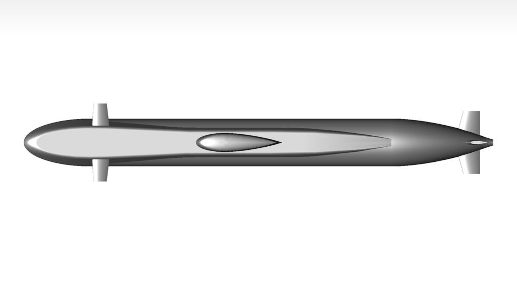
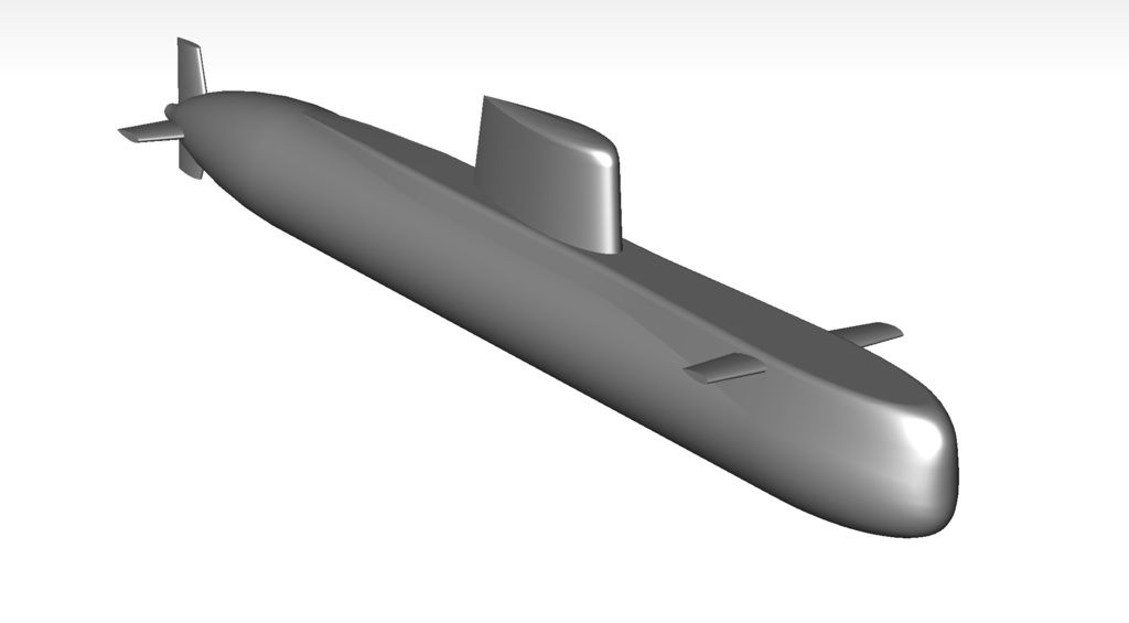
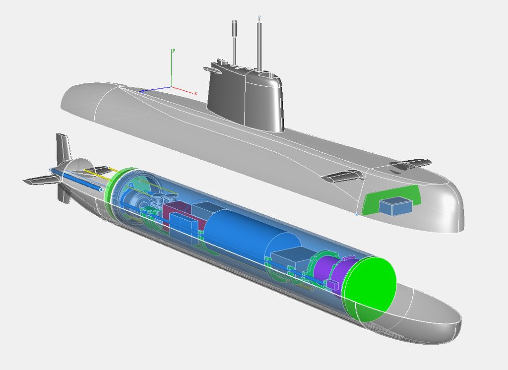
    Got a bit tired designing scale models on scarce info. So I took raw dimensions of a class 209 boat and got crazy with the rest. Those are the results:


    ]

    That's about it.....

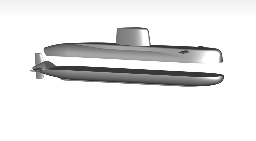
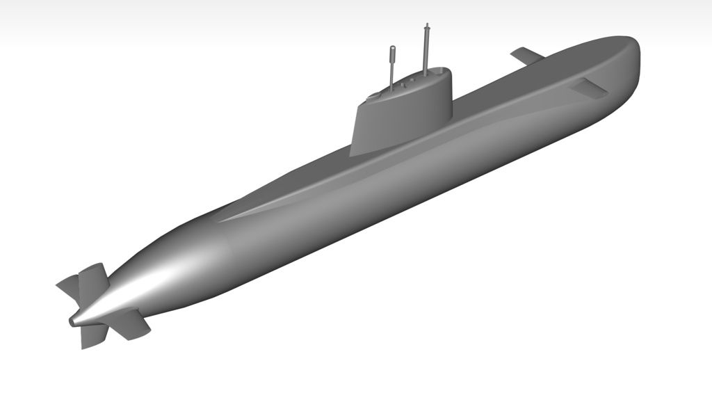
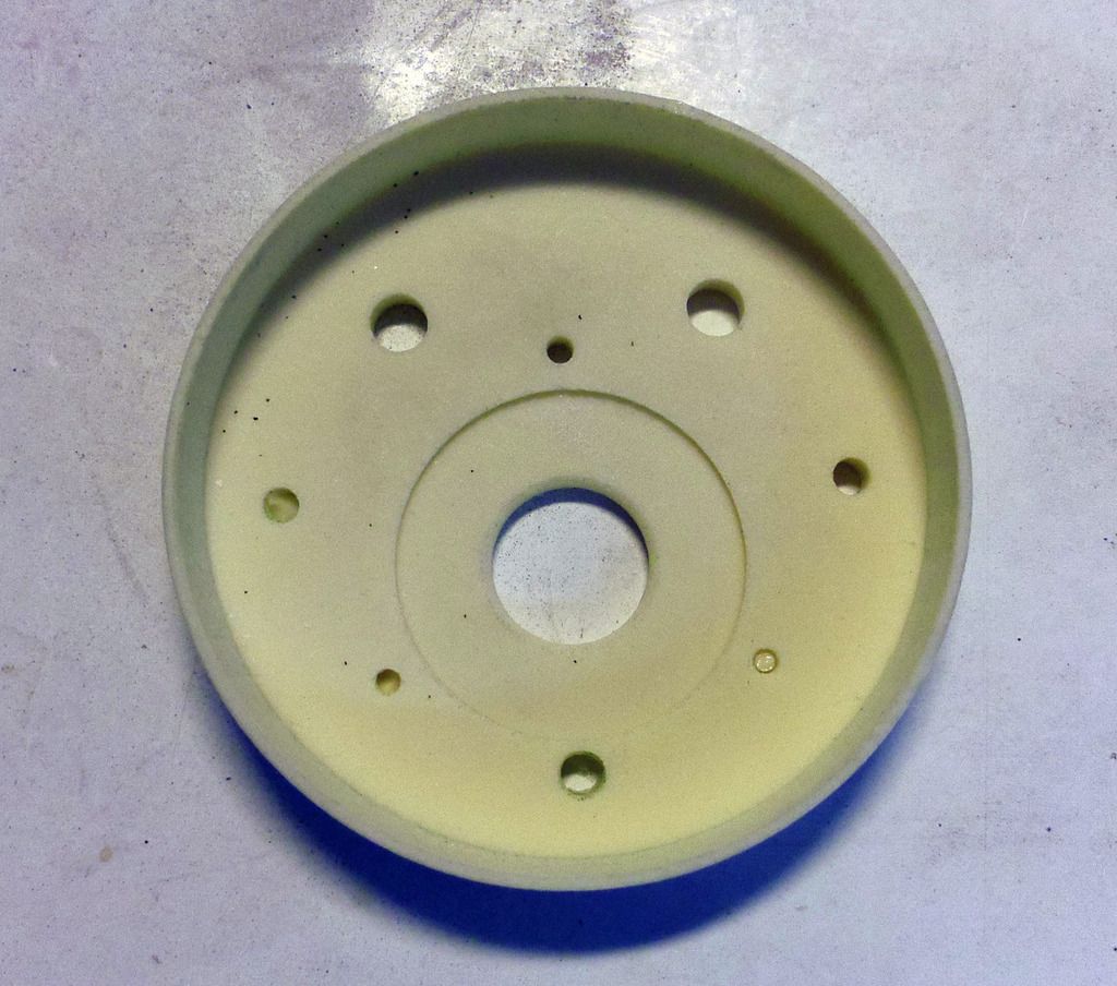
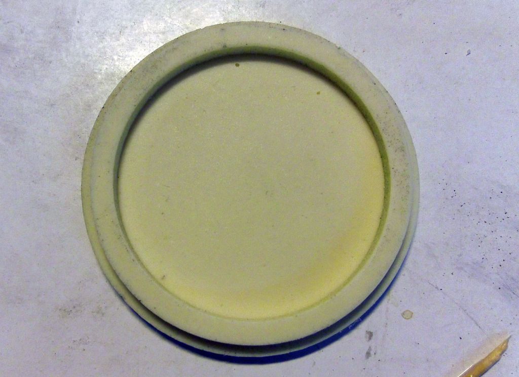
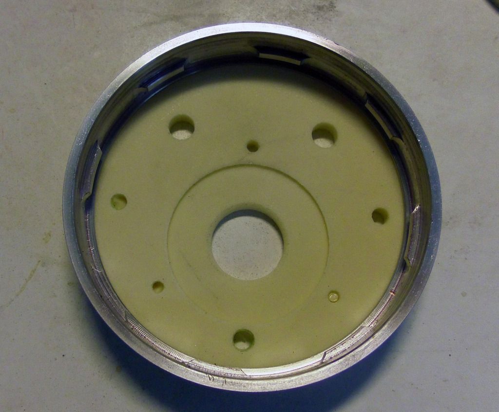
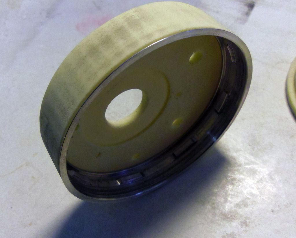
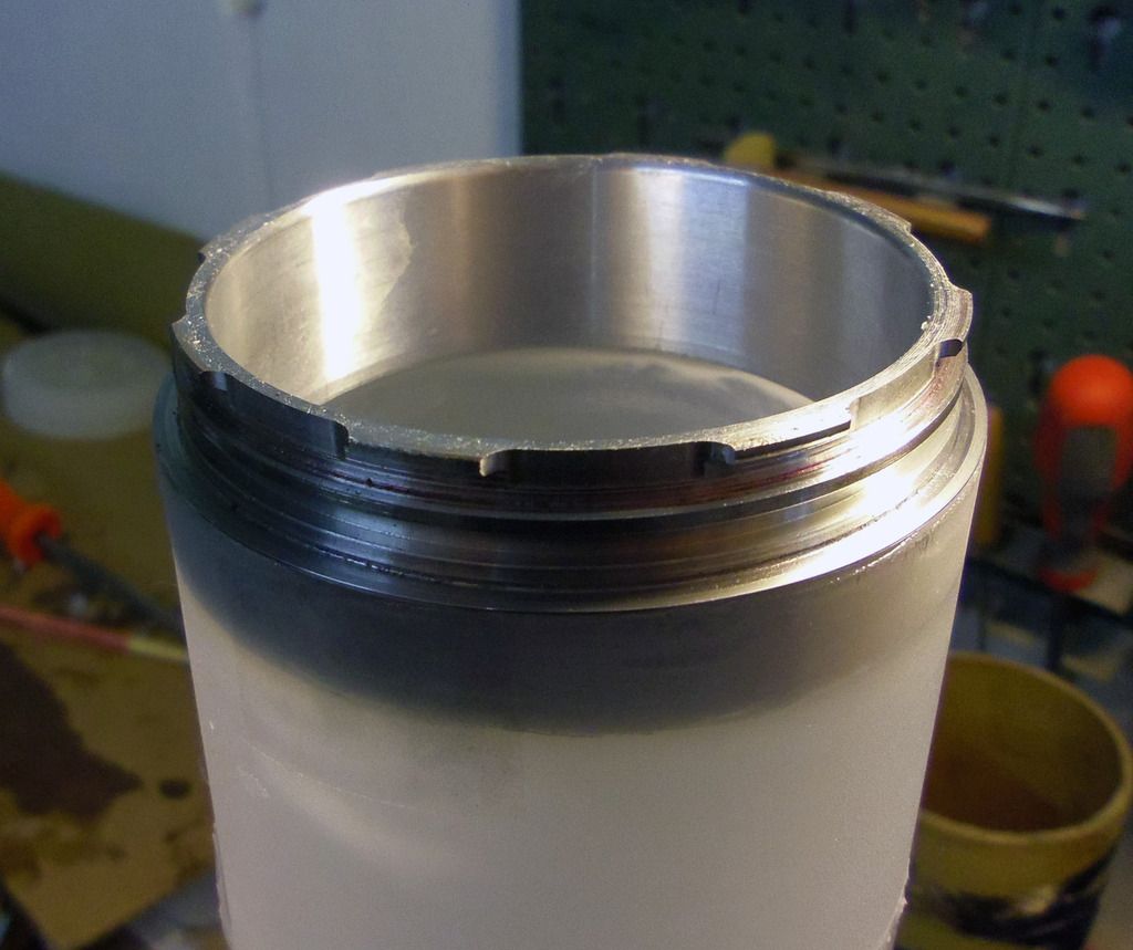
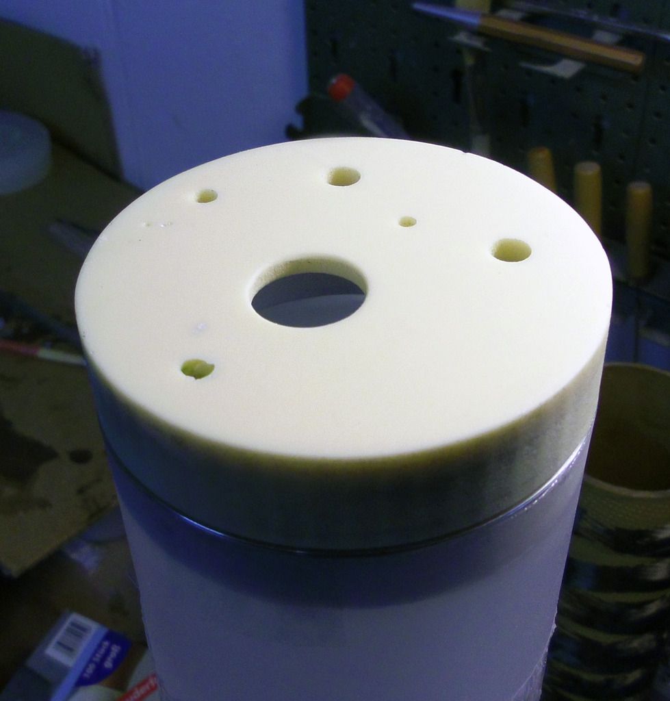
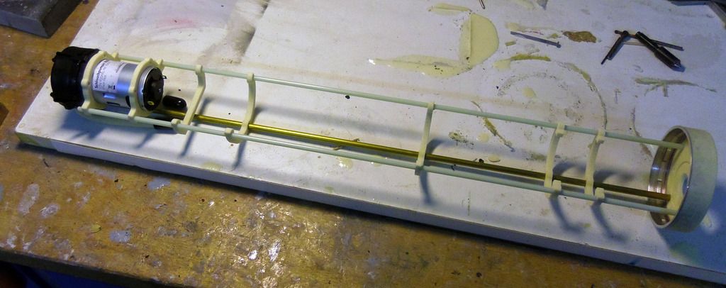
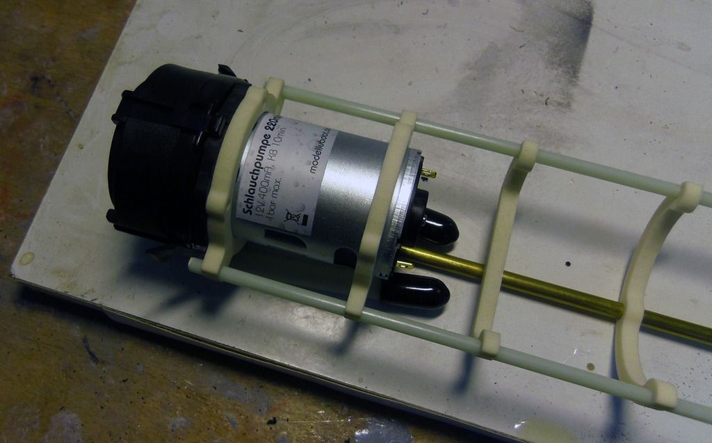
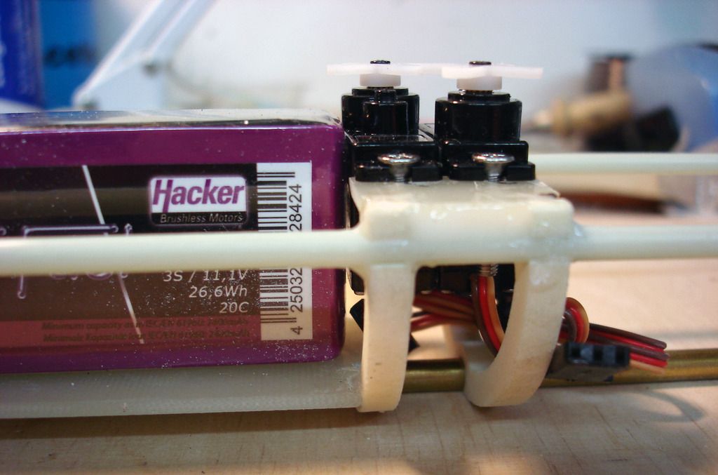
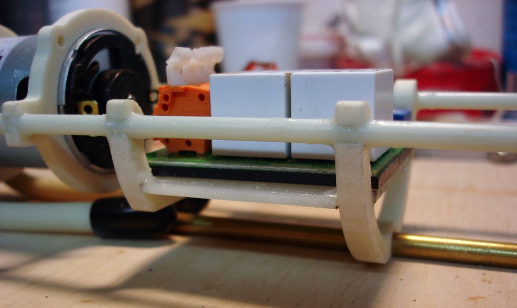
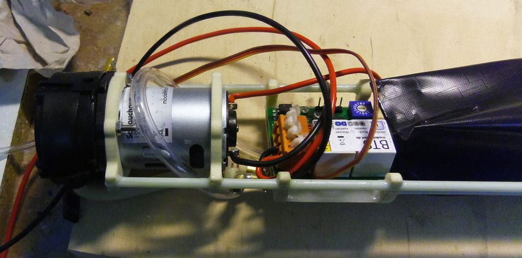
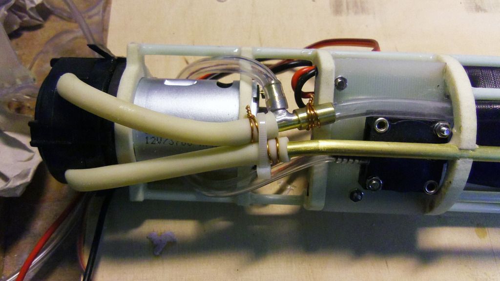
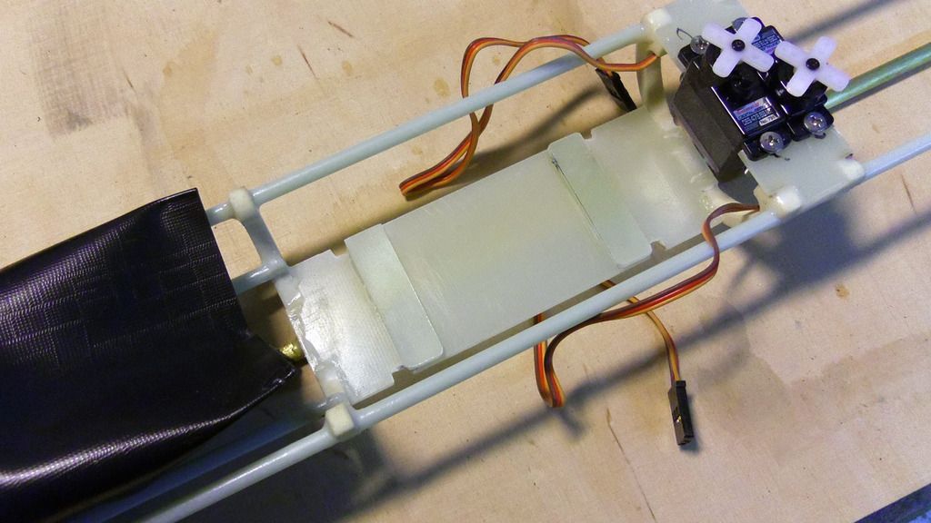
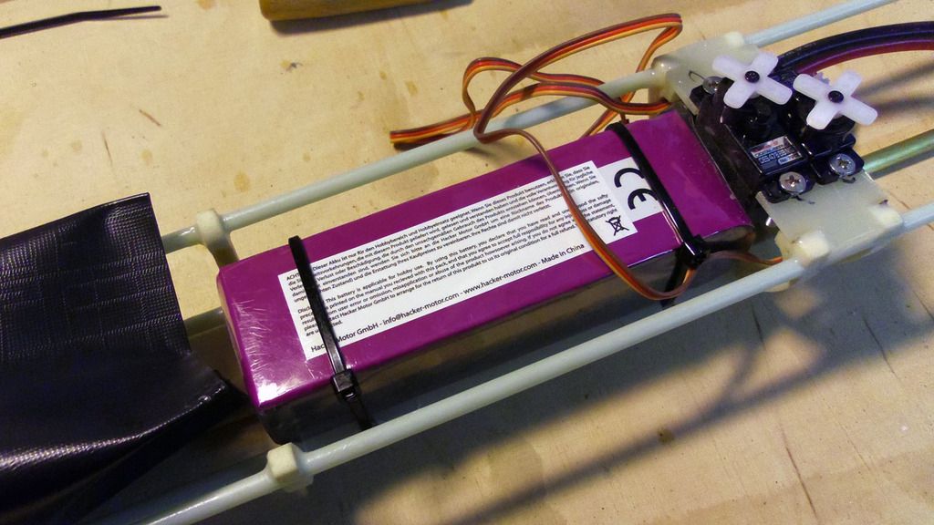
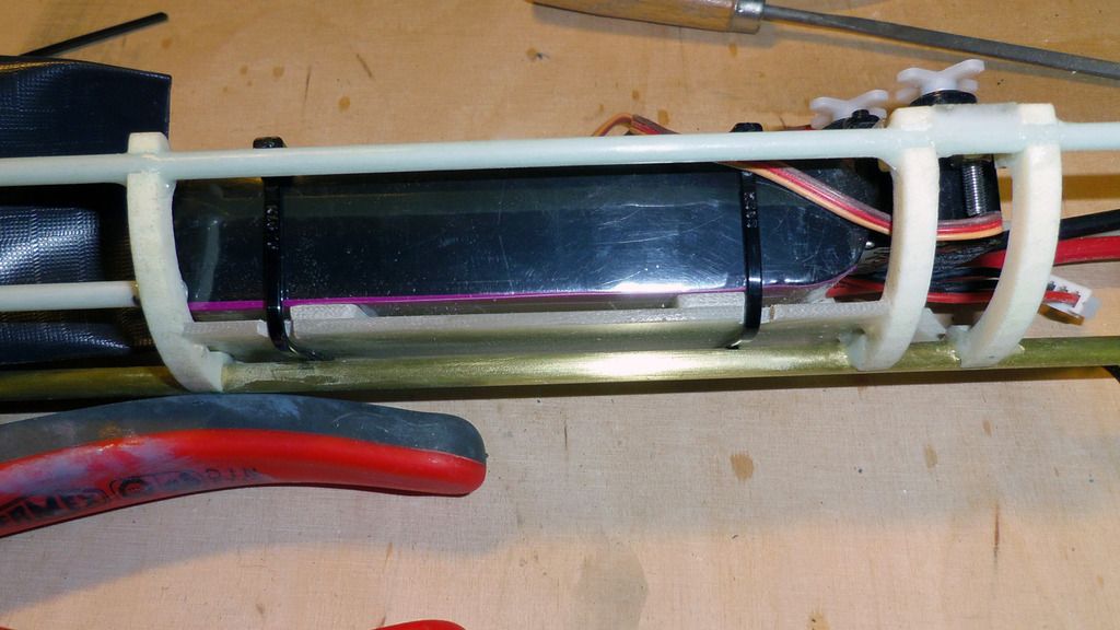
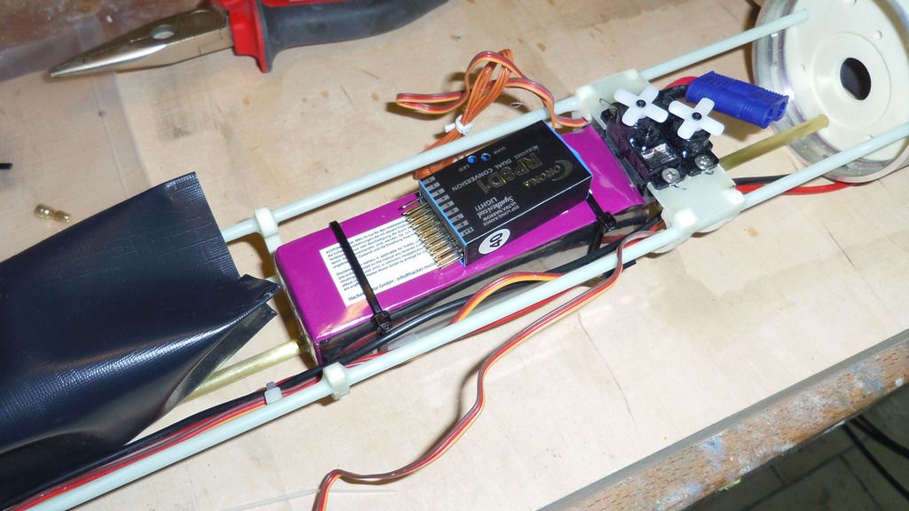
    Continued with the design of the WTC of the boat. Will be small and simple. Diving system is based on a peristaltic pump that pumps water into an infaltable rubber sack. Cheap, reliable, but a bit slow.

    Last edited by DrSchmidt; 03-16-2016, 12:04 PM.
  • greenman407
    Admiral
    • Feb 2009
    • 7530

    #2
    Nice drawings. A good way to start
    IT TAKES GREAT INTELLIGENCE TO FAKE SUCH STUPIDITY!

    Comment

    • DrSchmidt
      Captain
      • Apr 2014
      • 919

      #3
      The masters will be CNC milled. So there is the inherent necessity of having CAD drawings. The other big advantage is, that one can actually fit everything on screen. No need for improvising stuff afterwards.

      Comment

      • DrSchmidt
        Captain
        • Apr 2014
        • 919

        #4
        I already have posted some drawings of my fantasy boat project, which is loosely based on a 209 type. This is a project that I'm slowly starting right now. After the extremely complex U-1 and the still very complex Nautilus build, the modelers heart longs for something much more simple. This is going to be it...a small boat with WTC, single screw, no milled parts (with exception of the hull masters).

        It's going to look somewhat like that:


        I'll kick off with the WTC. All very simple. The structure parts were 3d printed. I'll make silicon moulds based on them and then cast PU parts. The dice system will use a peristaltic pump and an inflatable rubber tank.

        This si the design::


        And the first 3d parts arrived today....they are green because I ordered them on St.Patrick's day and green plastic was cheaper that day ;-)


        Bajonet catch fits tight:


        Comment

        • greenman407
          Admiral
          • Feb 2009
          • 7530

          #5
          All very interesting! So may I ask the source of these nice looking WTC parts?
          IT TAKES GREAT INTELLIGENCE TO FAKE SUCH STUPIDITY!

          Comment

          • DrSchmidt
            Captain
            • Apr 2014
            • 919

            #6
            They are CAD designed and then printed by a dutch company: Shapeways.com
            They ar going to be the masters for silicon moulds. The actual parts will then be cats in PU

            Comment

            • DrSchmidt
              Captain
              • Apr 2014
              • 919

              #7
              And here we go: To make reproduction easy I want to cast the structure parts using PU resin. Therfore I have to make silicon moulds from the masters. Glue the masters to a flat board, frame.....


              Cover everything in 2K silicon.....


              and we have a mould.


              And the first cast parts.


              Couldn't be easier.

              Moulds for the front and back bulkheads are next.

              Comment

              • DrSchmidt
                Captain
                • Apr 2014
                • 919

                #8
                As promised, the silicon moulds for the front and aft bulkhead are done, and the first parts are cast:


                The bajonet catch fits tightly:


                The counterpart is already glued into the WTC tube:


                And complete:


                Next is the inner structure...

                Comment

                • He Who Shall Not Be Named
                  Moderator
                  • Aug 2008
                  • 12256

                  #9
                  I can watch this guy work all day long! Most of us flop around in the dark till something works. This guy ... this guy seems to have it plotted out long before tool hits substrate. Doctor: you are a Machine!

                  M

                  Who is John Galt?

                  Comment

                  • DrSchmidt
                    Captain
                    • Apr 2014
                    • 919

                    #10
                    Thanks.....I try ;-)

                    Comment

                    • DrSchmidt
                      Captain
                      • Apr 2014
                      • 919

                      #11
                      Well, a quick snap together of the inner structure:


                      The end plate of the peristaltic pump has been trimmed to fit the PU cast supports:


                      Everything is held together by two 4mm diameter GRP rods and a 5 mm diameter brass tube, which also serves as water intake for the pump:


                      Well, basic inner structure done in about 1 hour - had worse deals than that:

                      Comment

                      • DrSchmidt
                        Captain
                        • Apr 2014
                        • 919

                        #12
                        During the week I glued together the part of the inner strcuture. The pump is screwed to the support frames. Behind it sits the pump controller on a 2 mm thick GRP board. The free space will hold the rubber sack for the water. Then the LiPos and behind them the two servos for the aft planes.


                        Comment

                        • DrSchmidt
                          Captain
                          • Apr 2014
                          • 919

                          #13
                          Slowly everything falls into place. The dive controller is screwed in place and I started wiring the whole thing:


                          The hoses are hooked up. The overpressure switch is new, not the one I got with the controller, as latter was too big. The new one fits tightly into place below the dive controller. The hose to the pressure switch starts in a T nipple and is routed over the pump motor to ensure that no water reaches the switch. And it looks cool....


                          The battery rest on two 2 mm thick GRP planks:


                          This way the battery can easily be fixed with cable ties:


                          The gap between battery the GRP deck has the advantage, that in case anything gets wet, the battery can easily dry. And the gap is well suited to route cable ties to fix additional gear:


                          e.g. the receiver. It will simply sit on top of the battery:

                          Comment

                          • DrSchmidt
                            Captain
                            • Apr 2014
                            • 919

                            #14
                            Well, as the guy who milled the masters for my other boats doesn't have the capacity to mill the masters for this boat, I looked and found a new one and will give him a try. I'll be wiser in a few weeks. The final result should look somewhat like that:

                            Comment

                            • DrSchmidt
                              Captain
                              • Apr 2014
                              • 919

                              #15
                              First pictures of the masters:


                              Comment

                              Working...