
Thanks for the tip. I have some time before I'm ready for the prop but I will call him now and then.
-
-
The Prop-Shop told me today they will ship my new prop by the end of this week. I'm keeping my fingers crossed. Now I'm looking for a circular punch set in the range of 1/4 to 5/8" to punch out grates for my main and aux. seawater intakes. I have thin brass stock that should work very well if I can find the right punch set. Can anyone give me a recommendation of where to look?
"Will" Rogers
SSBN659Comment
-
I recall I bought a set of punches from Harborfreight.comStop messing about - just get a Sub-driver!Comment
-
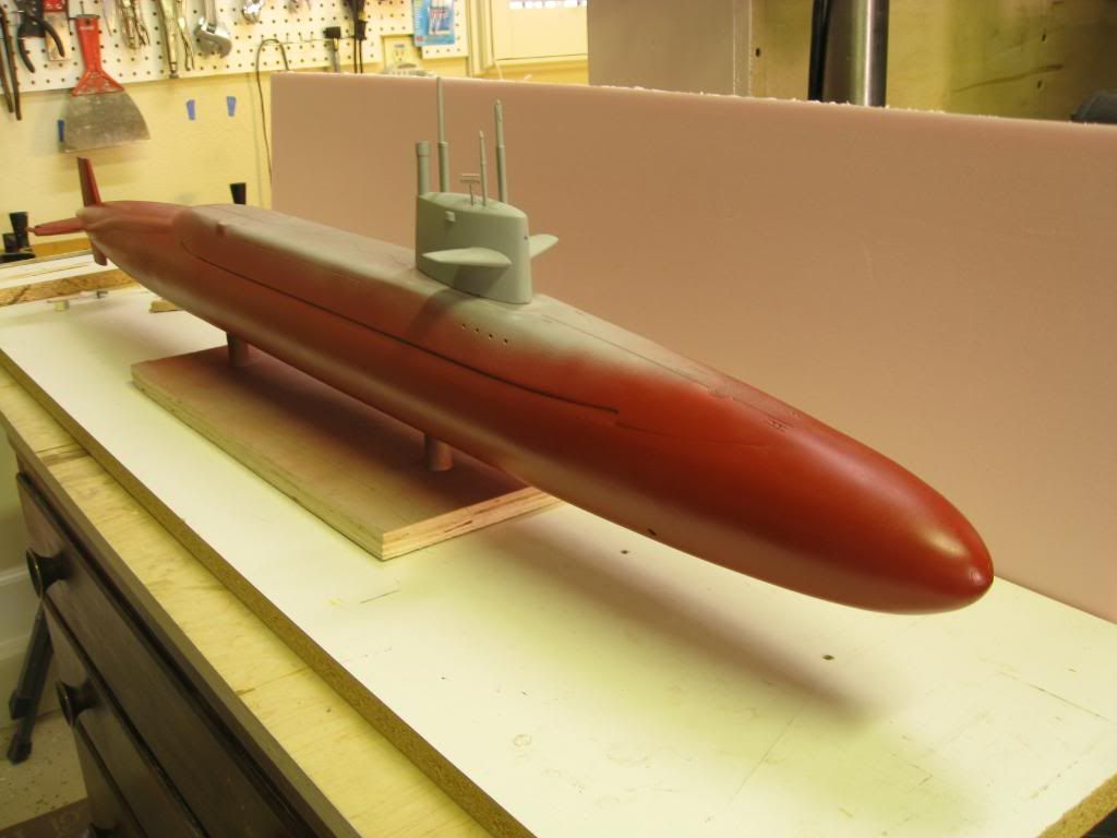
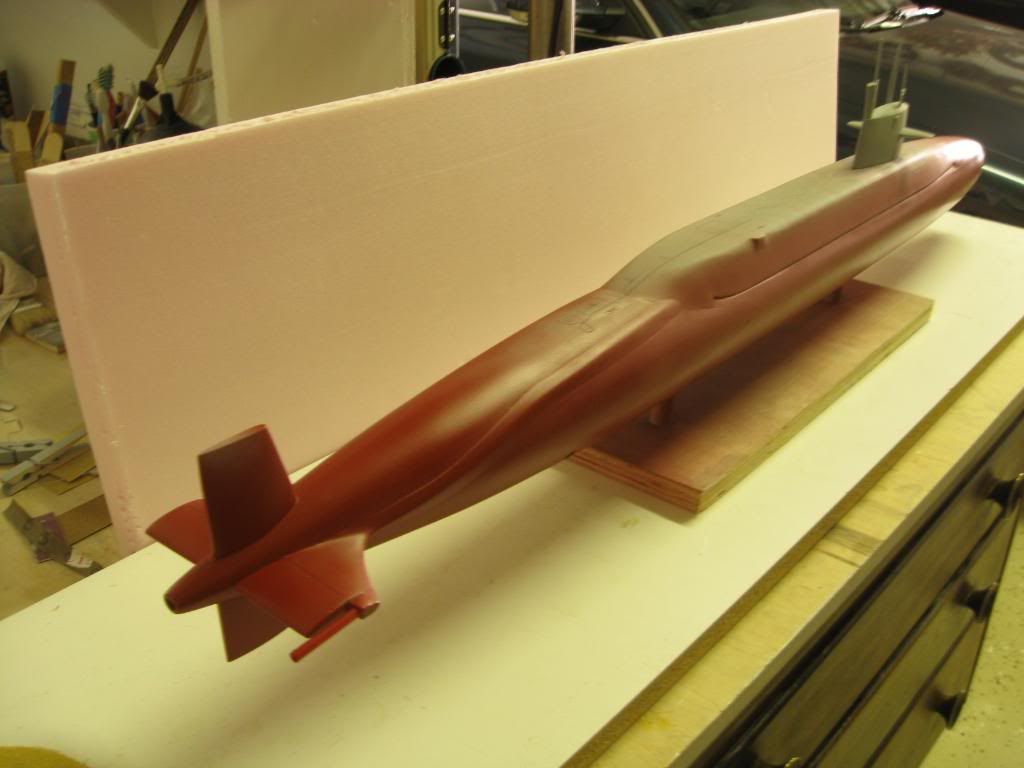
Progress on USS WILL ROGERS, last of the “Forty-one for Freedom”, continues. I’ve been working on the main deck scribing and fittings as well as painting the underwater hull. My plan is to paint up to just above the waterline first so I can mount the model on a stand that protects the underside while I continue work on the topside. In the two photos that follow the sail still has not been permanently attached. It’s just there for the photos and to verify what the final will look like. At this point I’ve laid out and drilled holes in the main deck for mounting the retractable cleats and capstans as well as the MBT vents. I wanted to do this while the deck is still in primer in case I had to correct any errors in the locations. All locations were penciled in and verified against my drawings before and after drilling.
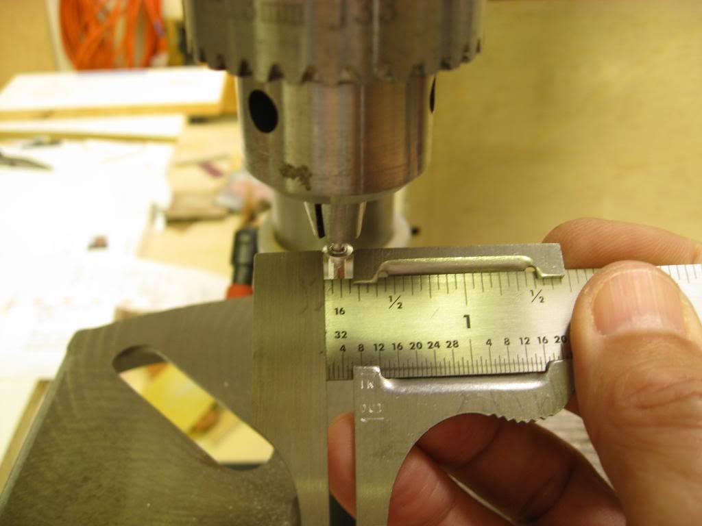
I think I mentioned in an earlier post that I would use HO gauge railroad spikes for the cleats. The spikes appear to be very close to scale. The next task was to make the capstans. For this I used 1/8 inch aluminum pop rivets. The rivet head was turned down using my drill press as a “vertical lathe” and a mill file to get to the diameter I needed for scale.
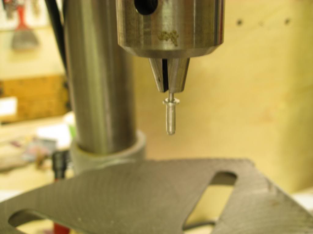
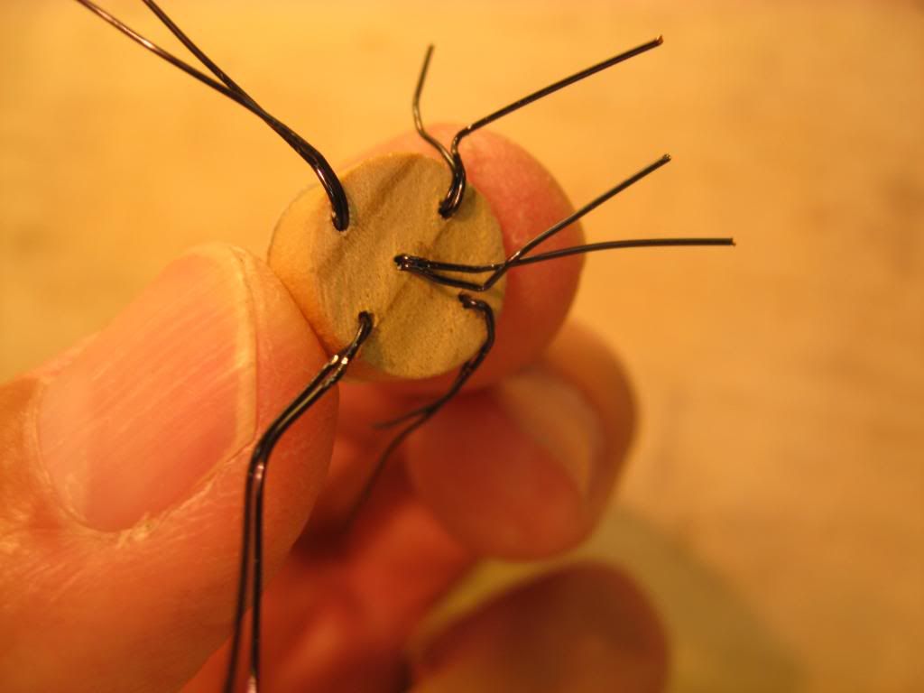
Not counting a couple of attempts that weren’t what I wanted I used 4 pop rivets to make the two capstans. After two rivet heads were turned down I cut off one head with my Dremel and slid it onto the shank of the second rivet as shown in the next photo.
Then I popped the heads off and reversed them on the shank, cut the nob off the shank and CA’d the two heads to the remaining shank. In the photo below the capstan on the top has been completed. The one on the bottom has yet to be popped off the shank and reversed but I think you get the picture.
The finished capstans will be CA’d into pre-drilled 1/8 inch holes in the main deck after the main deck has been painted. This way the finished capstans will not need any painting since the aluminum should look very realistic.
My plan for the MBT vents is to use small zinc coated nails with a 9/64 inch diameter head. The nails will be inserted into main deck holes with only the heads showing as the vents.
I’ve got other plans for the escape hatches but that will come in a later post.
“Will” Rogers
SSBN659Comment
-
Since my last post I received my prop from the Prop Shop UK. It came in record time. Unfortunately it went back in record time because the casting had some flaws. Fortunately the company has been very accommodating. They agreed to furnish another prop and it too arrived in good time. So in spite of some concerns I�ve heard about the company, I�m happy with their resolution of my issues.
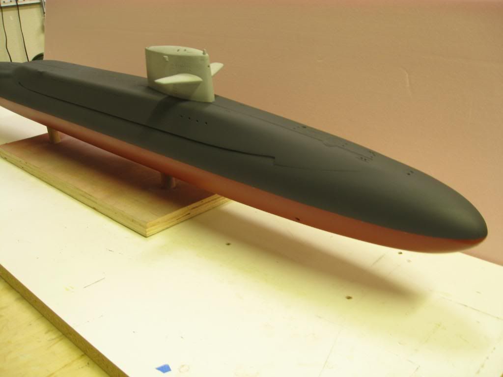
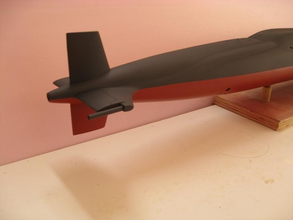
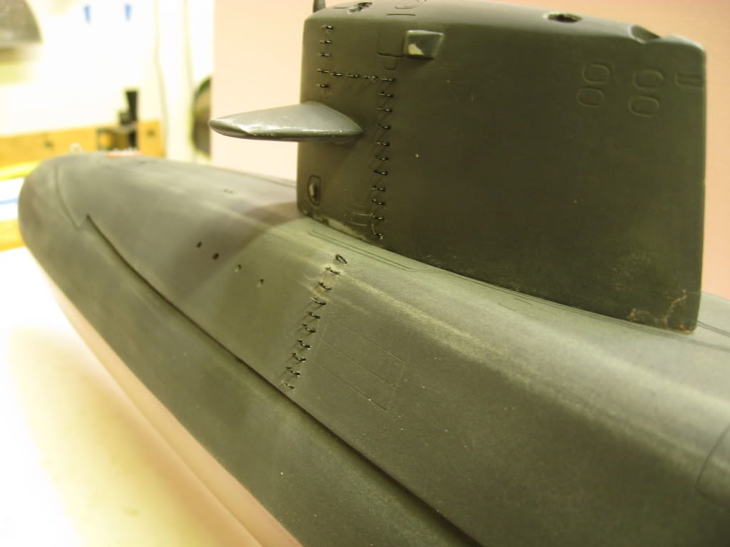
Now on to the hull. After painting the first coat of �Grimy Black� on the upper hull I set the sail (still in gray primer) on the hull to see how things looked. So far, so good. We�re getting closer to the finish line.
Meanwhile I�ve been working on the hand grabs that form the ladder on the sail. I made a template out styrene and taped it to the sail. Then using a very small drill bit in a pin vise I drilled out the holes.
Then I fabricated each grab out of #22 copper wire using my needle nose pliers to bend the shape. Each one is 3 millimeters wide. There are 64 holes on the sail alone and 32 on the hull. I should have drilled the holes before attaching the fairwater planes. It would have made the job a lot easier because the pin vise kept hitting the planes. It took a couple of days to drill out the holes and �fab the grabs�.
Then each one was inserted into the sail carefully using needle nose pliers and sometimes tweezers after CA�ing the legs of the grabs. After all 64 were glued into place I stepped back to admire my handiwork. After looking at it for awhile and comparing it to several different photos I have of the real ones I finally realized the scale was way off � too big! In addition, the holes were larger than the legs and I had no idea of how I was going to fill the gaps.

After mumbling a few choice words to myself I pulled out each grab so I could start over with 26 gauge copper wire. In the process of breaking loose the grabs, I also broke off one of the planes. Not my day. So, knowing it would be easier filling and re-drilling the holes without the planes I removed the other plane and filled the holes.
After filling and sanding the holes for the grabs and planes I started over, this time to use a #70 drill bit and 26 gauge wire. I drilled the holes using a new template and fabricated new grabs � took a couple afternoons just for the grabs. Then I reinstalled the planes and airbrushed the sail using Floquil�s �Grimy Black�. Then I inserted each grab in the sail and the superstructure � another time consuming task as each grab had to be fitted in the hole to make sure it was right, then removed and the legs dipped in gap filling CA glue and re-inserted.
Here�s what she looks like at this point after wet sanding with 600 grit paper.
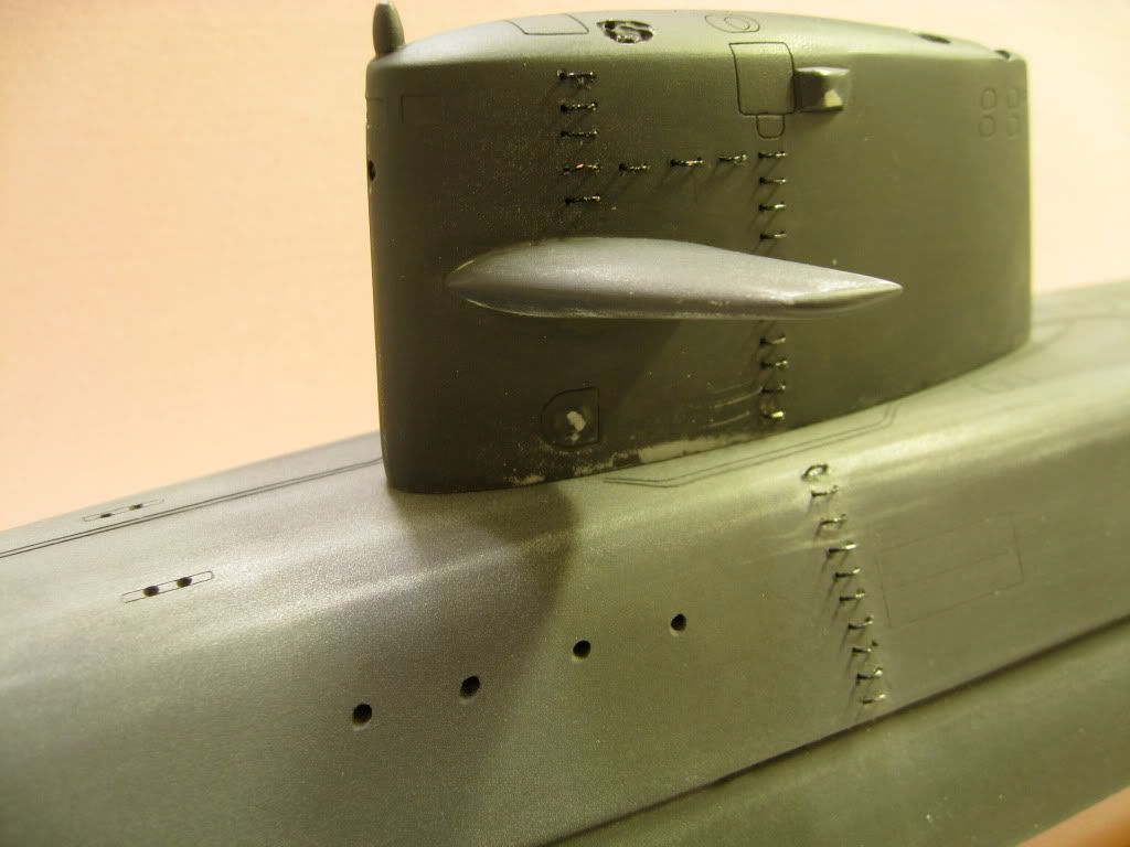
Some of the grabs need straightening and she needs a final airbrushing of �Grimy Black�. After that it will be some �Flat Black� on the main deck and planes but I�m getting ahead of myself so it�s back to work.
�Will� Rogers
SSBN659Comment
-
In my most recent post on this model I had painted the hull, wet sanded it and was getting ready for another coat of �Grimy Black�. I decided I didn�t like it - too black. The black made it look like the entire upper hull and sail were painted with �non-skid� paint.
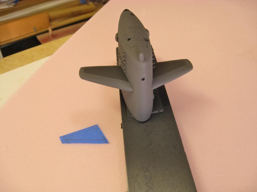
So I went back to my stock of paints and tested several different mixes to see how I could lighten it up a bit. With a bit the original black and some gray I mixed a color I thought was close enough to some of the pictures I had found on the web. Since I already had one coat of what I�ll call �non-skid� on the hull and sail I thought I would make the best use of what I had.
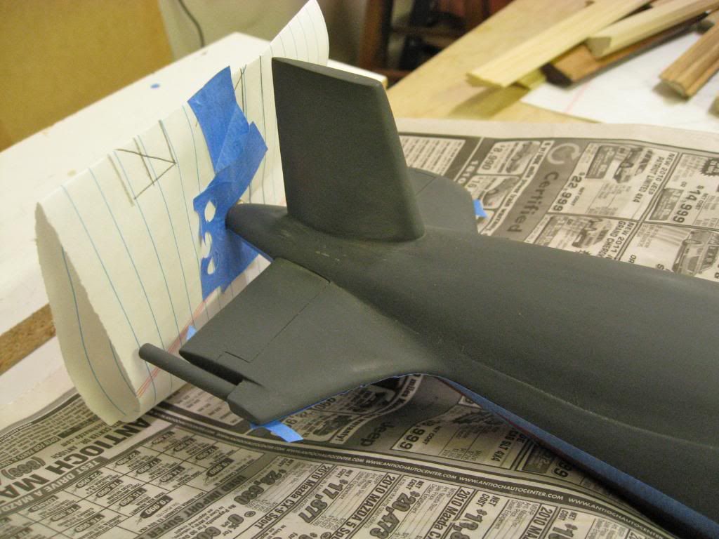
The sail had not yet been permanently attached to the superstructure so I masked the planes with blue painters tape. Then for ease of airbrushing I attached the sail to a foot long piece of 1X2 with double-sided tape. This allowed me to airbrush the entire sail and underside of the planes without painting my hand. Here�s the result with the �non-skid� on the planes standing out nicely.
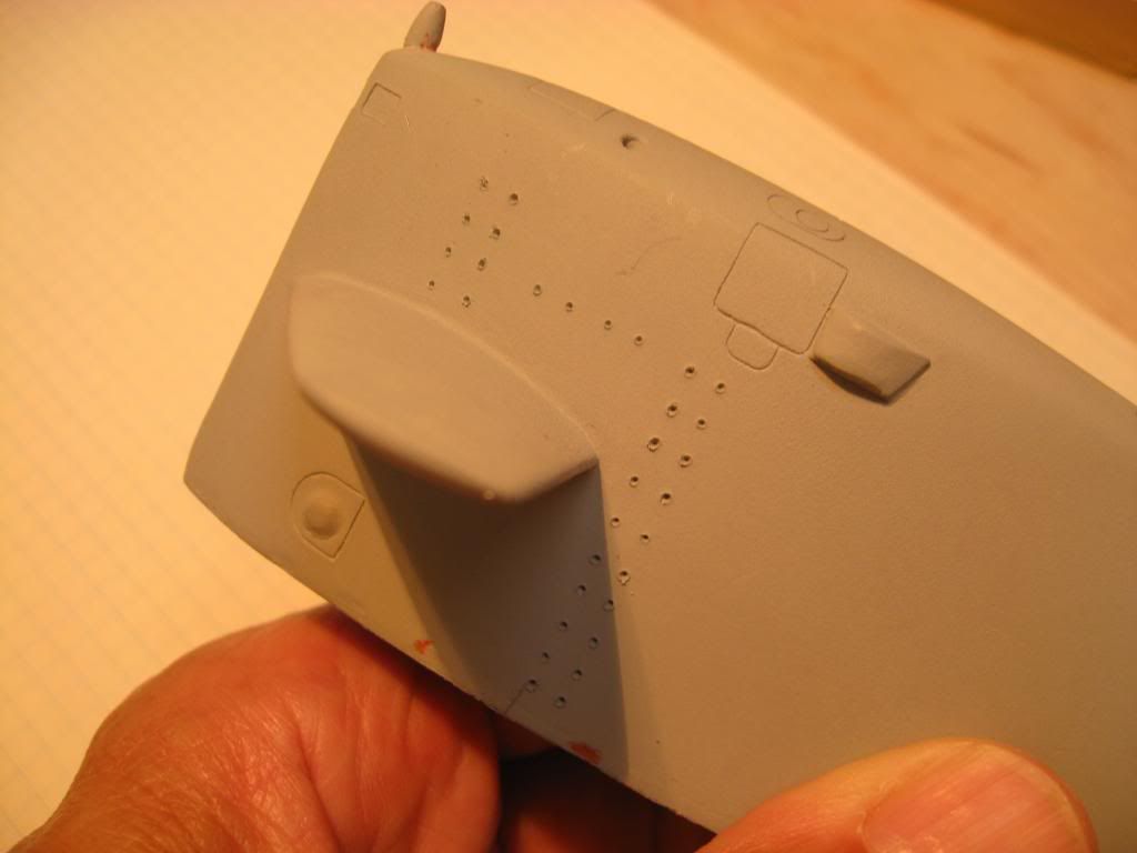
As I started to mask the main deck to save the �non-skid� I found a couple other things I wasn�t happy with. First, the escape hatches just didn�t meet my expectations. Also, the location of the retractable cleats on the port side forward was too close to the centerline.
I drilled out the escape hatches with a Forstner bit and fabricated new �flat� hatches to glue in place.
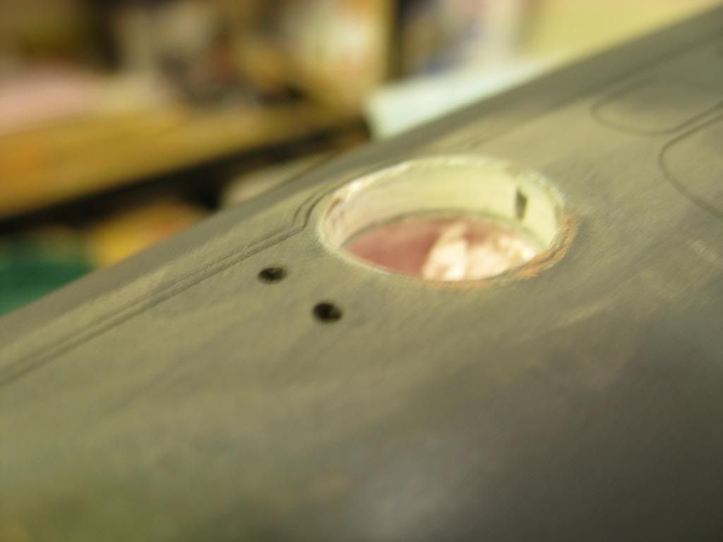
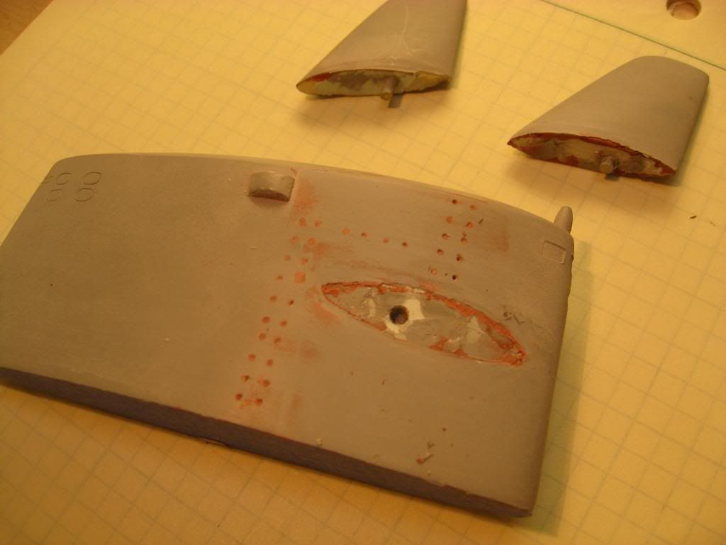
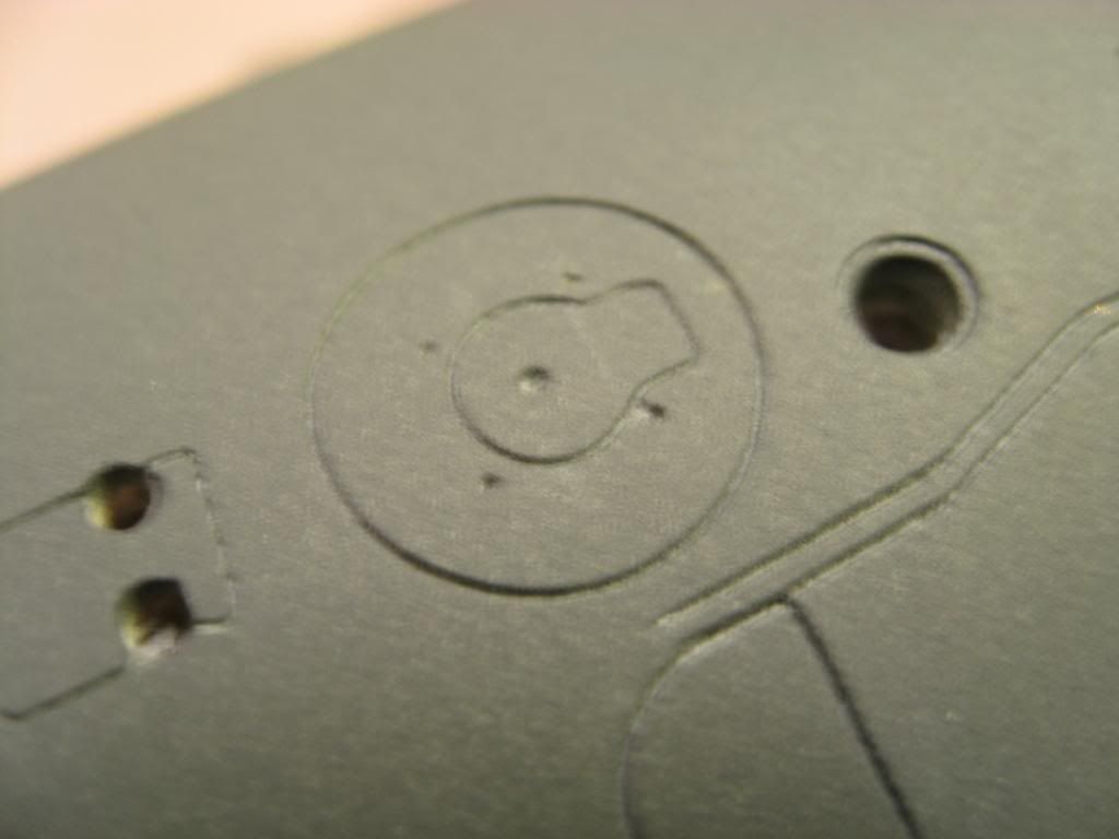
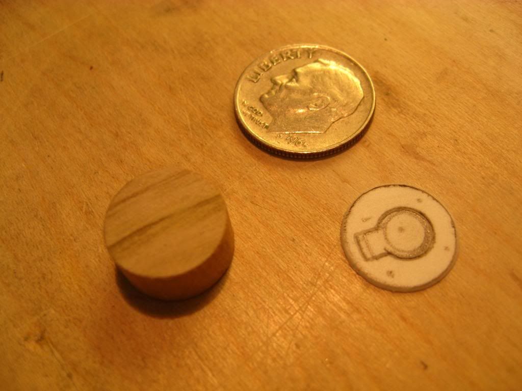
First I cut a piece of � inch dowel to fit into the holes I had drilled. Next I drew a hatch on a piece of .015� styrene. Using round and square templates I scribed the hatch as shown below. I also marked the location for the grabs for a rescue chamber.
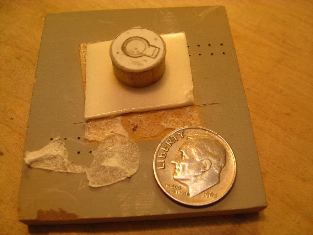
Then I glued the styrene to the dowel and attached the assembly to a piece of scrap with double-sided tape. As you can see the piece is small and I didn�t want to drill my hand while drilling the holes for the grabs.
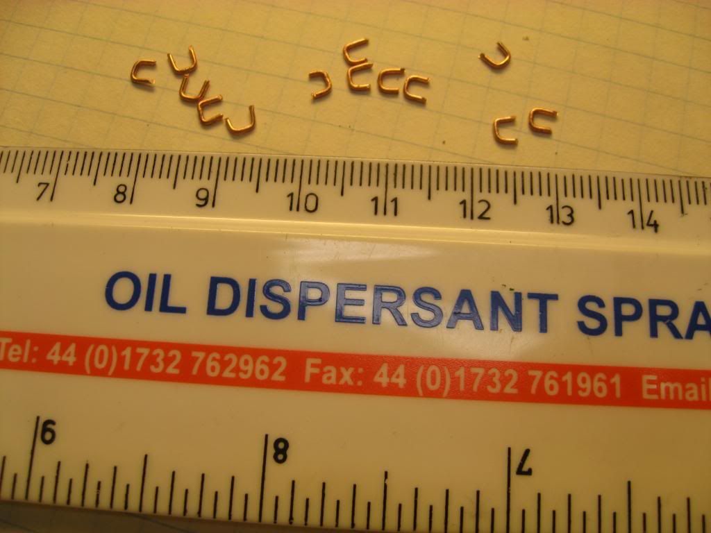
I used a #20 gauge wire brad to drill five holes then bent #26 gauge copper wire into U shapes to form the grabs. The legs of the U were made long enough to insert through the assembly and pull them tight enough to form a grab that looks close to scale. Once I was satisfied they looked okay, I used gap-filling CA glue on the under side to secure them in place. When the glue had dried, I snipped off the excess wire on the bottom.
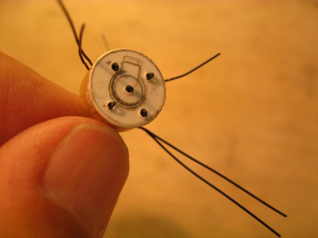
Finally, I looped a piece of wire through the center grab and temporarily inserted the hatch to see how it fit. It fit just fine so I lifted it out with the piece of wire and set the hatch aside for priming and final painting.
You can also see how I relocated the holes and scribing for the retractable cleats. Next step � more sanding and painting.
�Will� Rogers
SSBN659Comment
-
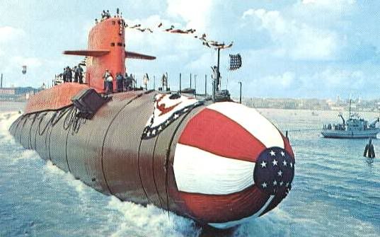
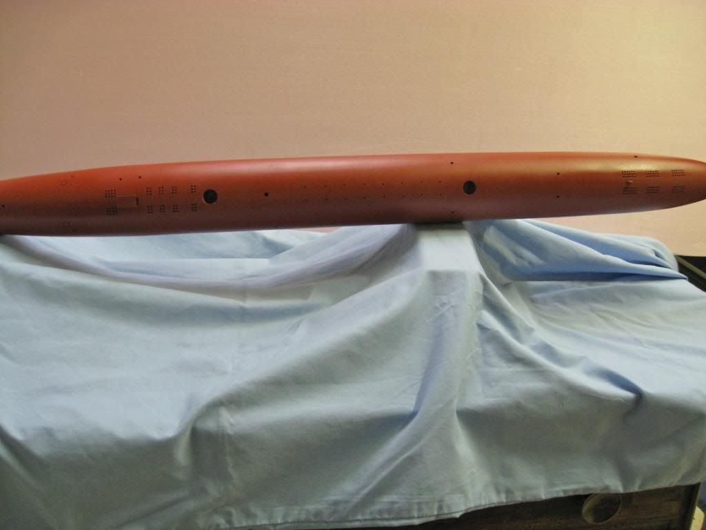
Back when I started my model I hadn�t thought too much about the paint scheme I would use. Then some months ago my thought was to go with what I thought was a typical launching scheme, i.e. red anti-fouling below the waterline and black above. When I started researching I found some different choices.
This is the Daniel Boone SSBN 629), what I thought the typical launch scheme looked like. And I did find several boats painted this at launching.
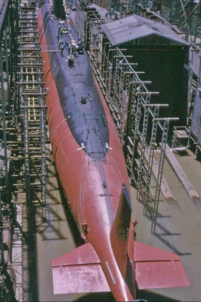
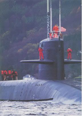
Then I found that Will Rogers was different. She was likely painted with red anti-fouling below the waterline but then with a black boot-topping from the centerline up to about the waterline before launching. I read that the red anti-fouling paint did not hold up well when hit with wind and wave action and so the reason for boot-topping. If you look closely at the following picture, I believe you can see what I think is the boot-topping. It is a different black than the rest of the hull.
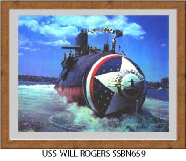
Since I was modeling the Last of the Forty-One for Freedom, I thought I�d check to see what the First of the Forty-One looked like when launched. What a surprise! If anyone out there can explain that scheme please share it with us. This is USS George Washington � SSBN 598.
For my model I finally chose to go with the as launched scheme but with a grey black above the centerline to represent what the boat might have looked like in later years, maybe having recently come out of it�s last overhaul. This is all guesswork mind you but it works well for me.
At this point I just about finished painting the model but I wanted to step back and share some of my research with you since I thought it was interesting.
In my next post I�ll cover some of the finer details I�ve been working on behind the scene as I waited for glues and paints to dry.
�Will� Rogers
SSBN 659Comment
-
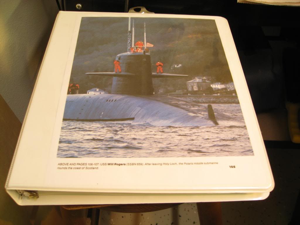
It�s been almost a year and a half since I started actual construction of this model but my research started over 10 years ago. Now the completion is very near and I�m down to �the host of other goodies� I mentioned in my very first post.
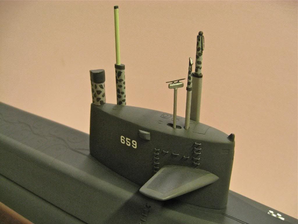
This binder contains my research photos and sections of various plans. The photo on the cover along with others was my guide to the various masts I wanted to represent. Each mast as well as all other fittings except for the propeller had to be handmade. I just didn�t have the tools nor the skill to make a suitable prop.
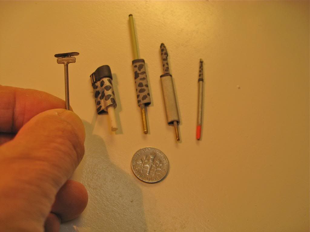
In the photo below you see from left to right: the surface-search radar, snorkel induction/exhaust, AN/BRA 15 antenna (MF/HF), No. 2 periscope (radar/ECM), and No.1 periscope (attack). Each mast was hand shaped using a combination of brass rod, brass tubing of teardrop and circular cross sections, styrene tubing & strips, blue masking tape strips and wooden toothpicks, believe it or not. I followed the paint schemes I found in the research photos as best I could. It�s a good thing there were so many of these boats because although they were not all exactly the same, they were similar in most respects. I also had some help from a former Will Rogers crew member. Thanks Bob.
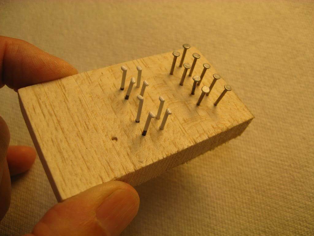
On the main deck I used model railroad spikes for the retractable cleats and #18 gauge wire nails for the main ballast tank vents. The spikes were painted white and the wire nails painted aluminum. Here they are drying in a scrap piece of balsa.
For sacrificial zincs at the rudder and stern planes I used some small pieces of black cable ties I had left over from another project. I cut them to length, secured them to blue tape and painted them aluminum. Then using one of my carving tools I scored each one three times to simulate four zincs.
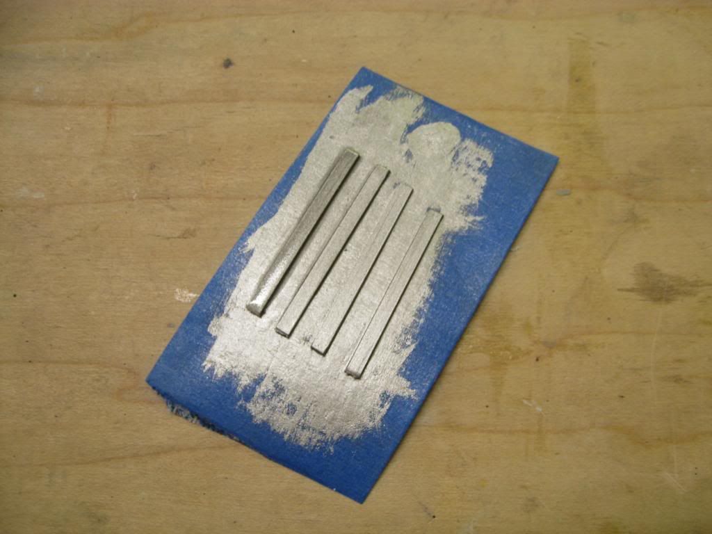
I thought they worked just fine. By the way, the stern/anchor light was cast in resin using an LED as the master and pressed into clay for the mold. I drilled a very small hole in the top of the rudder and the light. Then I glued a piece of 26 gauge wire into the light and then glued the assembly into the rudder.
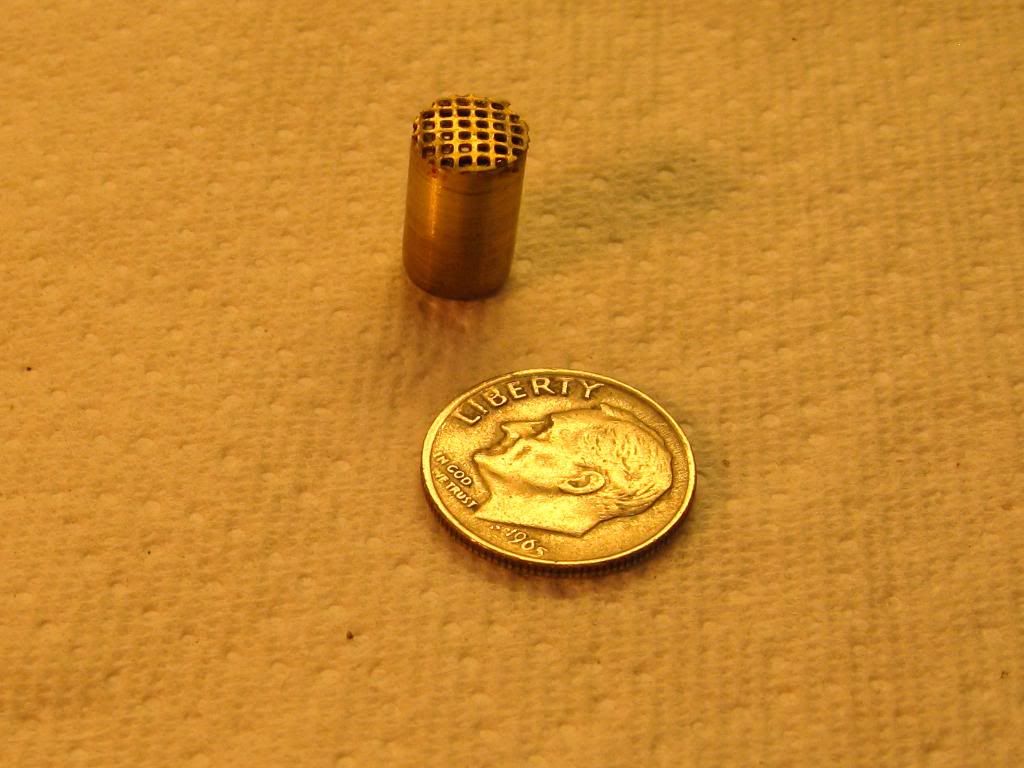
For the cooling water intake screens I found some etched brass at a hobby shop called �Just Trains�. Since my local hobby shop closed a few years ago I�ve been able to find many things I can use that were meant for the railroad train hobby. Hey, whatever works! I found an open punch set at Harbor Freight (thanks for the tip Mike). I used two different sizes to punch out brass screens for attaching to brass tubing.
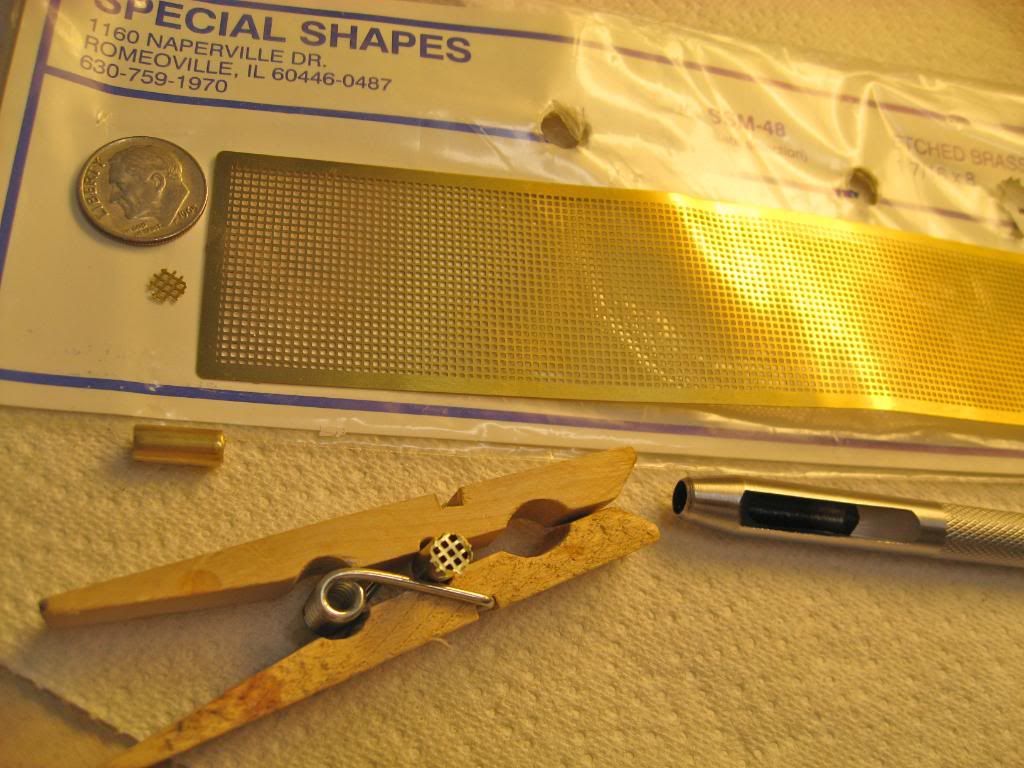
The challenge was attaching the screen to the tubing. I tried soldering them but that didn�t work as well as I had hoped. In the end I CA�d the screens to the tubes. The final assembly was then inserted and CA�d into the holes I had pre-drilled into the hull way back when.
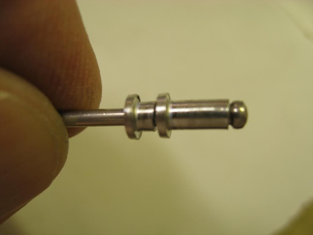
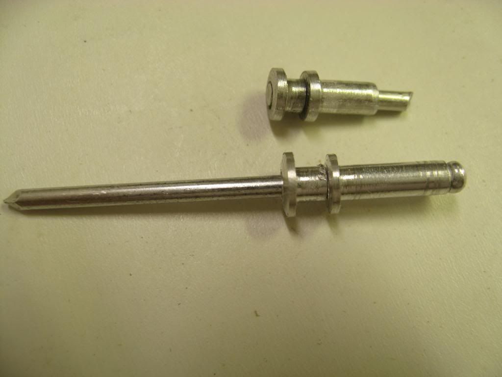
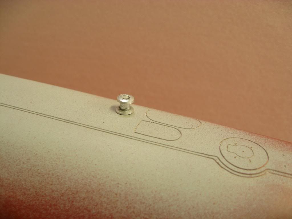
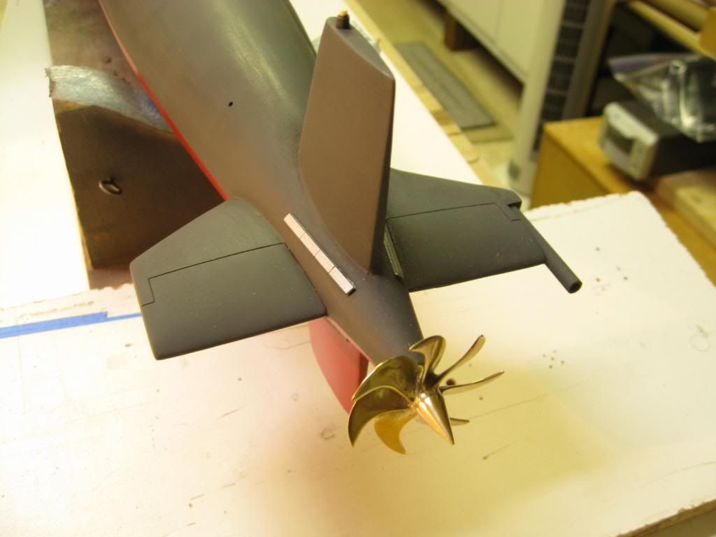
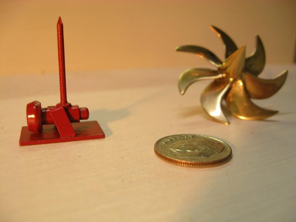
And now for the last �goodie�. I was able to find one fairly good photo of the Secondary Propulsion Motor on the Henry Clay in drydock. Believe me folks, there are some good pictures of these boats on the web if you are willing to do the research. Anyhow, using the picture and the drawing I made the SPM using styrene, Evercoat filler and CA glue. The Evercoat filler was spread heavily around one end of the tubing and allowed to dry. Then using my vertical lathe, aka �drill press�, and sand paper strips I shaped the SPM. The cover plate and brackets are styrene and the mount is a brad. Here you see it next to the prop in the first and deployed in the second photo.
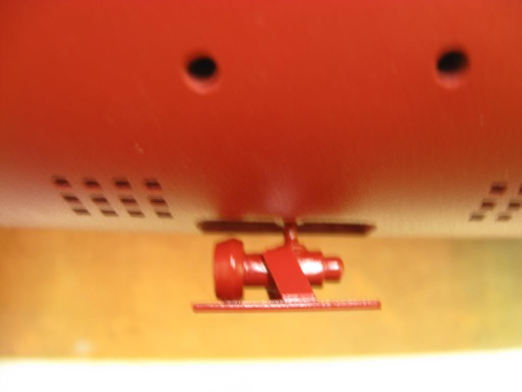
Each of these fittings except for the �zincs� has a �rod� of some sort to be inserted into pre-drilled holes in the sail or hull to provide support.
In my next post I�ll talk about marks and hull number.
�Will� Rogers
SSBN659Comment
-
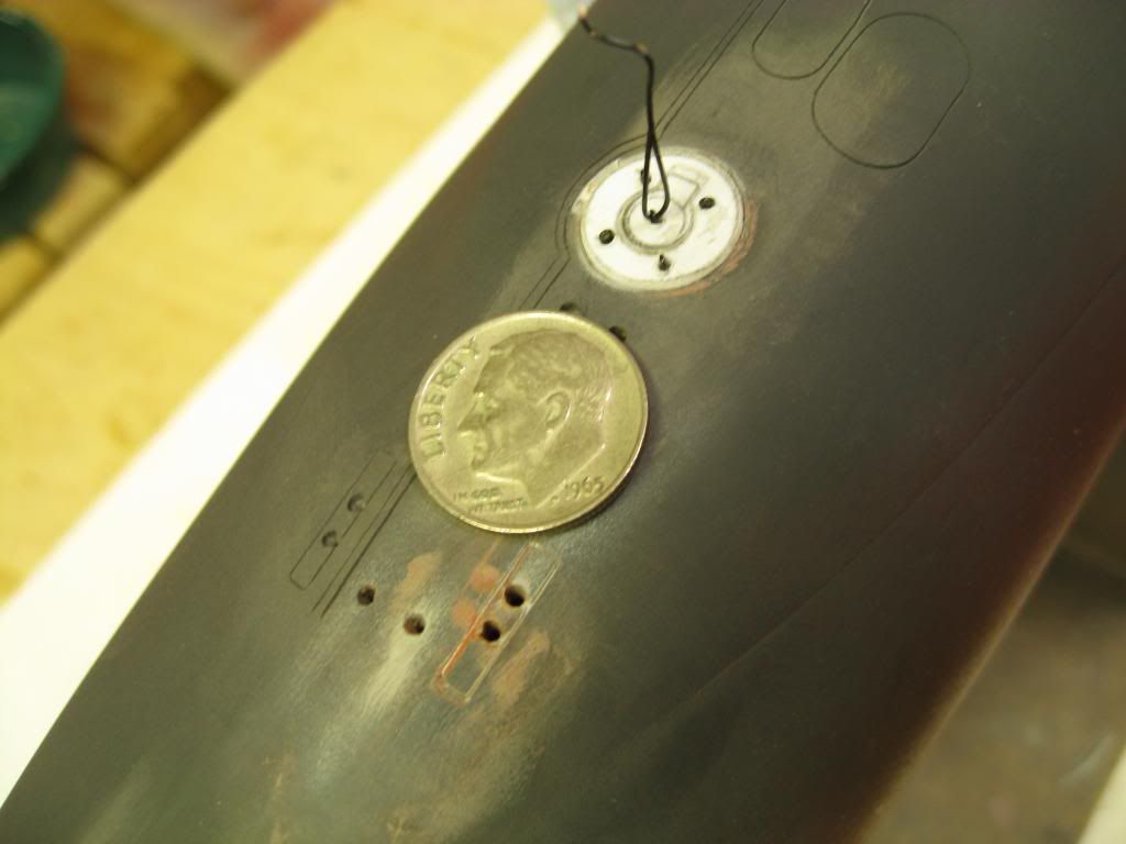
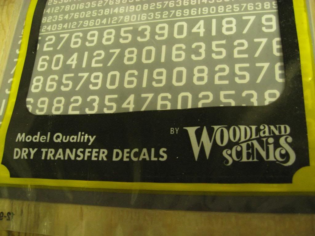
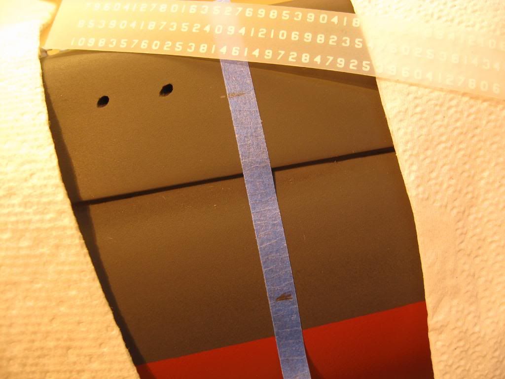
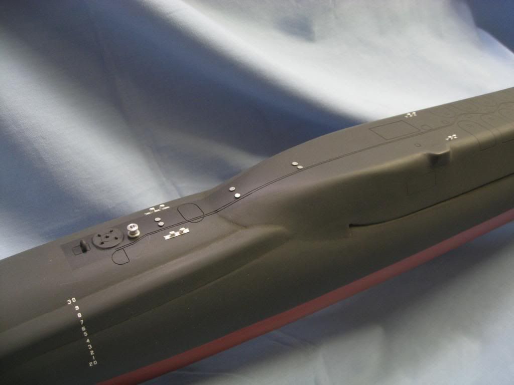
For draft marks and hull number I use Gothic style dry transfer decals by Woodland Scenics from my local hobby shop. Unfortunately my local hobby shop closed about 3 years ago so these decals are very old. Fortunately they still worked just fine.
One issue I had before starting was what size numbers to use for the draft marks. Full size draft numbers are 6� high with 6� spacing between the numbers. At a scale of 1:120 the closest I could come to scale was transfers that were 1/16� high. And this would require spacing less than 1/16� between them. Oh well, it sure beats trying to paint them by hand.
The next step was to layout in pencil on blue tape marks for the bottom of the lowest number and the top of the highest number. The tape also served as a guide to align the numbers vertically. Then to keep from leaving marks on the hull I laid down paper towels where my hands would rest.
Once the number strip was aligned I rubbed a pencil over the decal and the number was transferred to the hull.
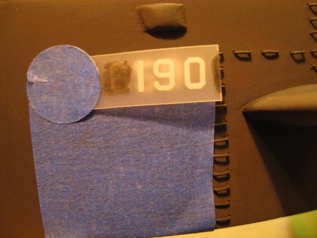
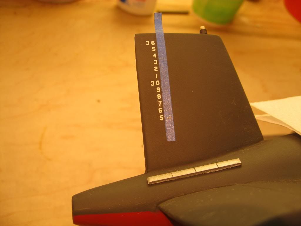
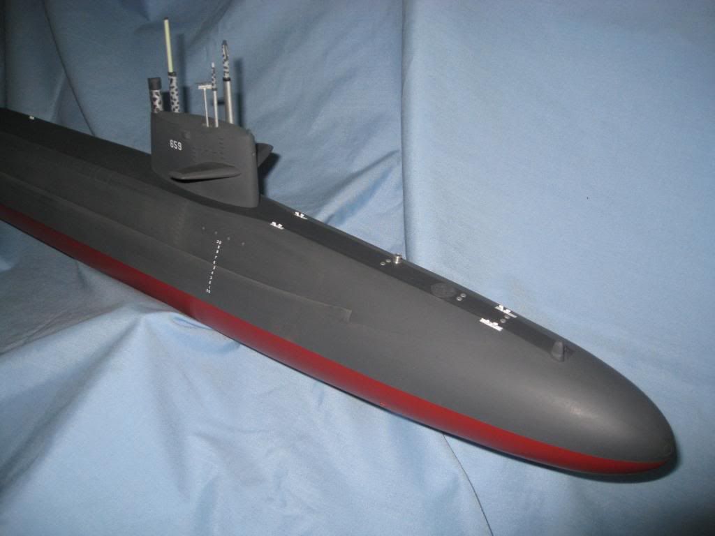
For the hull number on the sail I used �� transfers that would be 30� high in full scale.
I used blue tape again for horizontal alignment on the sail. Because the sail is small I also used a piece tape to hold one end of the decal strip in place before rubbing it with a pencil. Note how I had to cut off a small strip of transfers to fit the sail. I first transferred the 9 followed by the 5 and finally the 6 to avoid touching previously laid numbers. I reversed the sequence on the other side of the sail. Until the decals dry and are sprayed with a clear coat it is easy to smudge them.
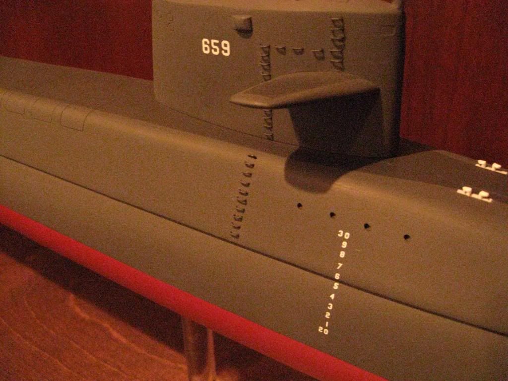
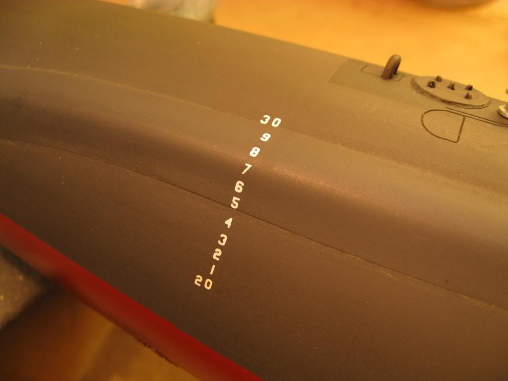
Here are shots of the hull number and forward draft marks and the after draft marks with a coat of clear coat for protection.
The draft marks on the rudder were laid out the same way.
Unfortunately there is a problem. Someone who worked on these boats in drydock noted my zincs looked too large for this scale. He referred back to the picture of the Daniel Boone in an earlier post to show my error. Good catch! Anyhow, I did some research on zinc anodes and I�m making new ones closer to scale. The ones you see in this picture have already come off and I�m getting ready for another airbrushing to touch up the paint in that area.
Once that�s finished I�ll do another coat of clear coat and get on to installing the masts.
�Will� Rogers
SSBN659Comment
-
When I started construction of this model in April 2009 I knew it would take over a year to complete it. So I took hundreds of pictures along the way to document what I did in case I wanted to do another model. I�m not sure what that model will be but this one is now finished except for the display case that is being fabricated as I write this.
For those who have not read the entire thread or who may not remember what it looked like at the start, here is what the beginning looked like.
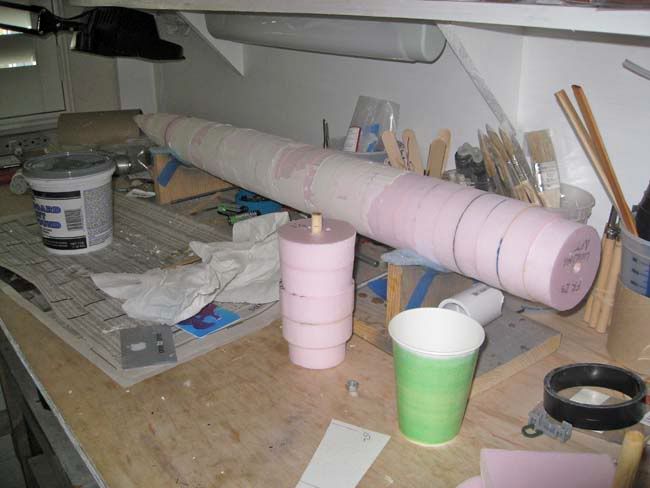
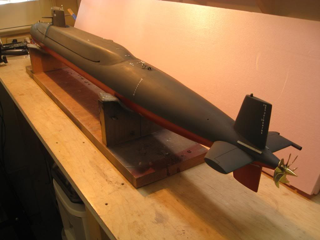
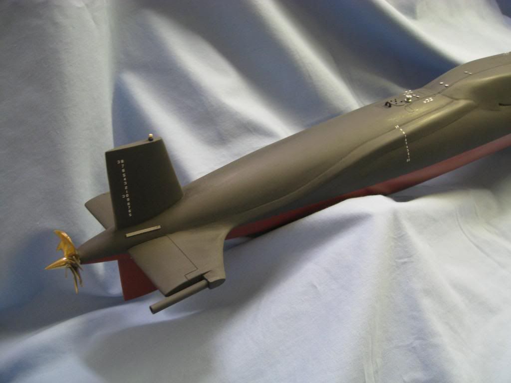
It�s been a long haul, but here is USS Will Rogers (SSBN-659) as she is today in my office at home waiting for the display case. The base is a piece of � inch birch with poplar panel molding side rails and stained in cherry. The supports are 5/8 inch clear acrylic rods.
I�ve also included a shot of the bottom showing the main ballast tank flood holes, missile tube compensating system ball-valve openings, main condenser seawater intakes and discharges, auxiliary seawater intakes and discharges, secondary propulsion motor, and a host of other hull openings including the trash disposal unit discharge.
Recall in my previous post I had been informed that my zinc anodes were too large for 1:120 scale. With some research I came up with an anode size of about 8 feet long by 6 inches wide and made the corrections. Cutting off the original anodes meant re-sanding and painting around the rudder. The work also required redoing the rudder draft marks. Since the prop had already been installed and the bottom hull painted I masked as shown below to protect around the work for painting.
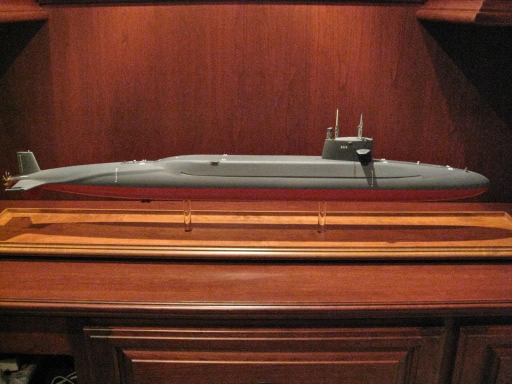
Once that work was finished, I installed the masts. Each one was hand made using a variety of different materials and hand painted as shown. I don�t know how often, if ever, all the masts I�ve modeled would have been deployed at the same time. I used a picture of USS Will Rogers departing Holy Loch as my guide for the masts but it didn�t show the snorkel intake/exhaust nor the surface search radar deployed. I added them for effect.
The next three photos show the details on the main deck and sail working forward from the propeller to the bow.
The display would not be complete without the �builder�s plaque� so I�m having one laser engraved in black background with gold lettering at a local trophy shop.
It will look like this:
USS Will Rogers (SSBN-659)
Benjamin Franklin Class Ballistic Missile Submarine
�Last of the Forty-One for Freedom�
Built by Electric Boat Division of General Dynamics Corp., Groton, CT
Laid down 20 Mar 1965 Launched 21 Jul 1966
Commissioned 1 Apr 1967 Decommissioned 12 Apr 1993
Model by William C. Rogers, Sr. Scale 1:120
At this point I thank, again, all of you who offered help in the way of information, tips and suggestions in completing this project.
FWE
�Will� Rogers
SSBN659Comment


Comment