Modeling the last of the forty-one for freedom

Collapse
X
 
  • Time
  • Show
Clear All
new posts
  • SSBN659
    Commander
    • Feb 2009
    • 405

    Modeling the last of the forty-one for freedom

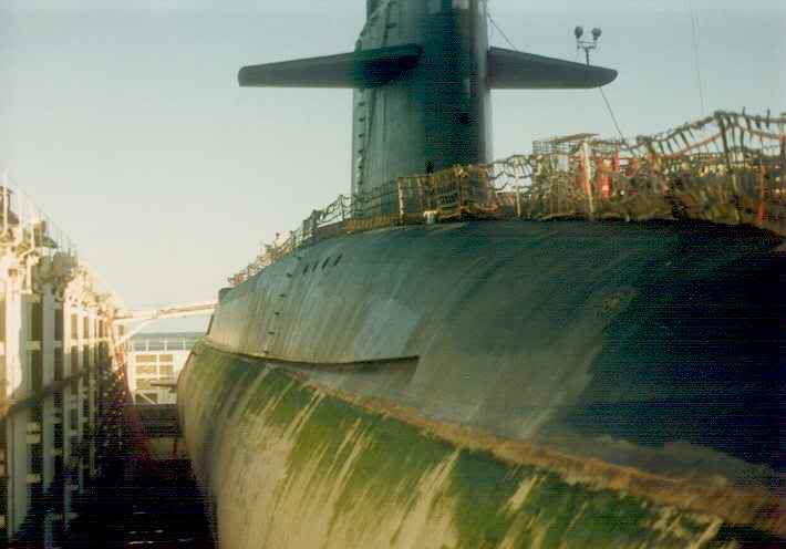
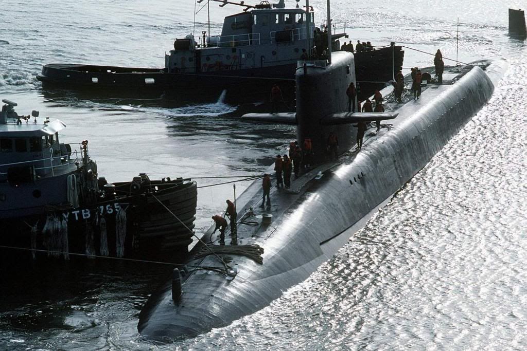
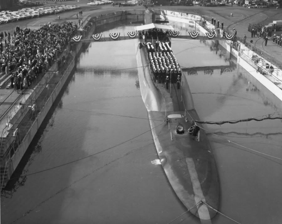
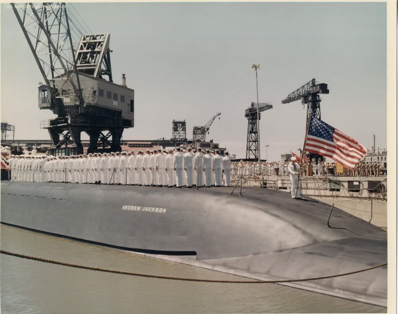
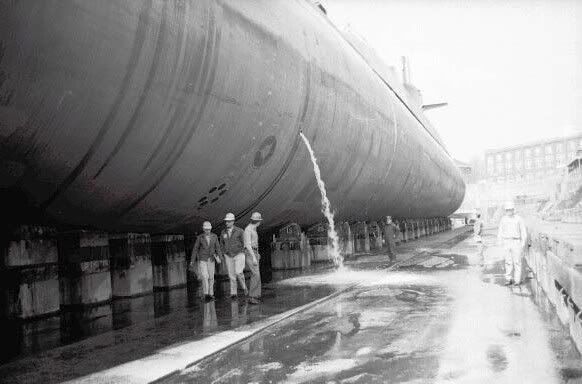
    "Forty-one For Freedom" was the name of the US Navy project that commissioned and deployed 41 ballistic missile submarines during the cold war. These nuclear submarines were designed to deliver the first generation of submarine-launched Polaris missiles to enemy targets in the event of a nuclear war. The Forty-One For Freedom program ran from the deployment of the USS George Washington in 1960 until the deployment of the USS Will Rogers, the last of the Forty-one For Freedom in 1967.

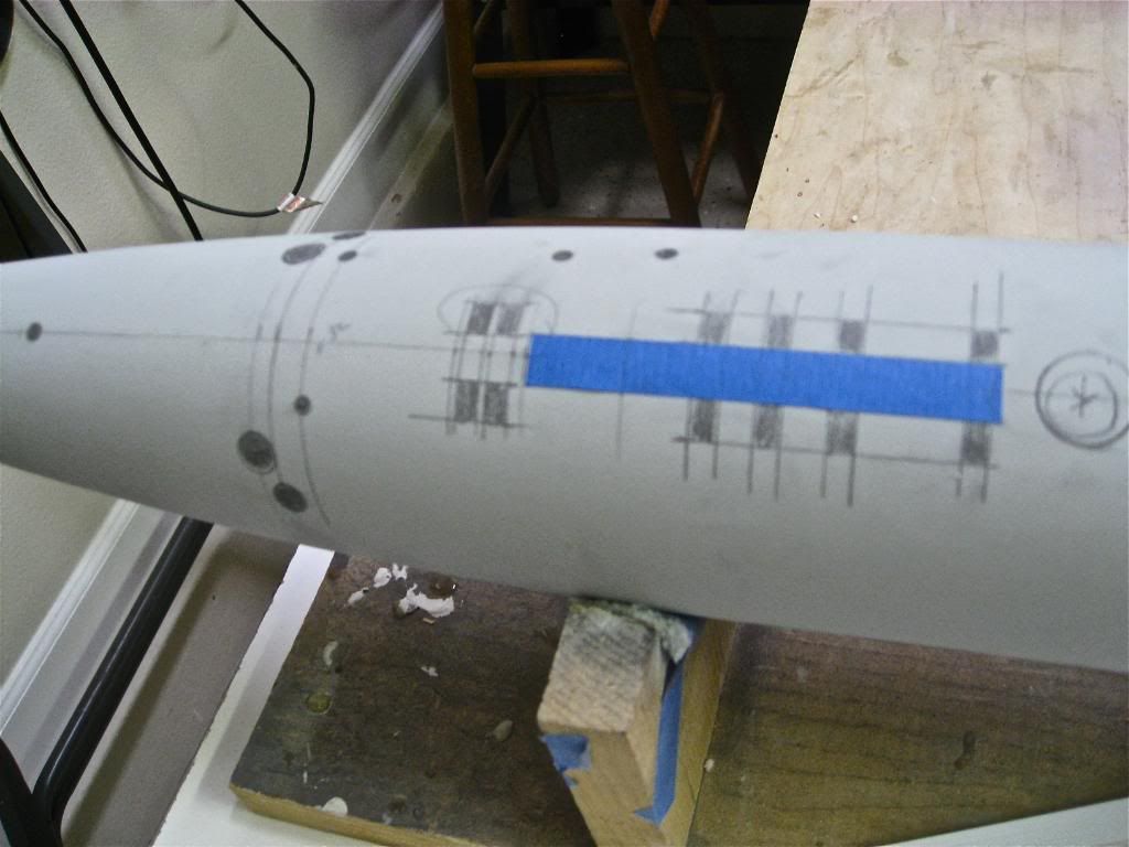
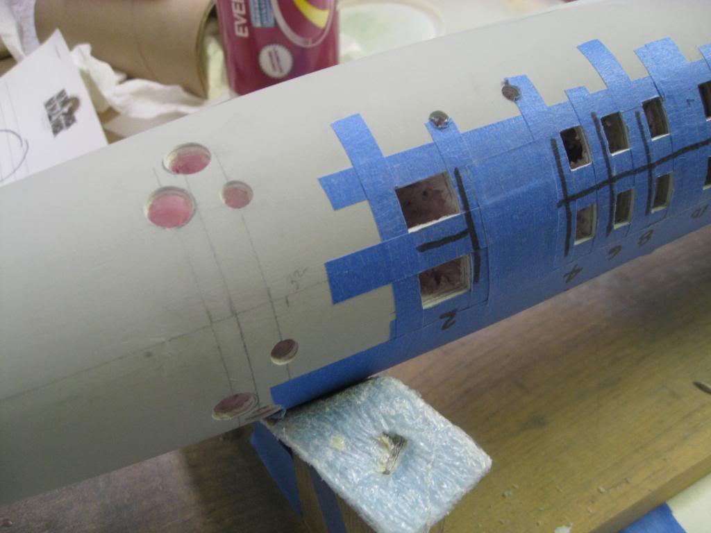
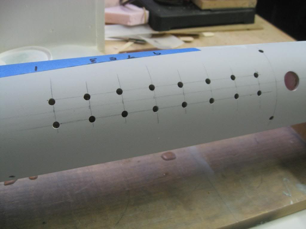
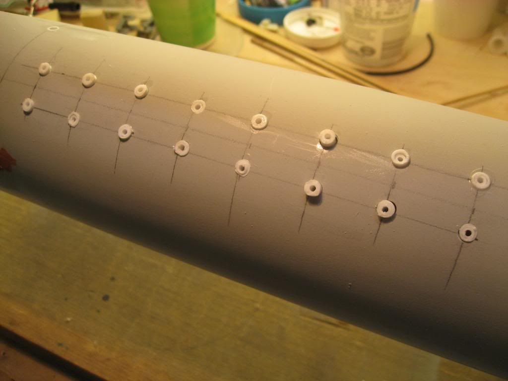
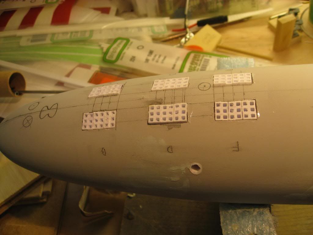
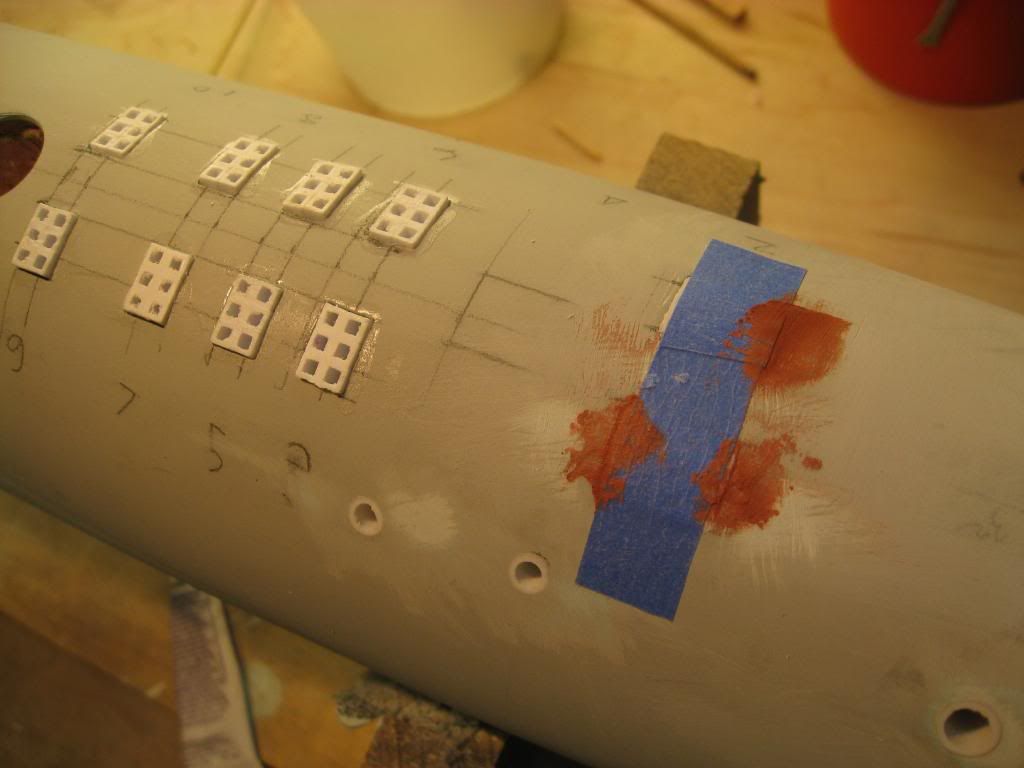
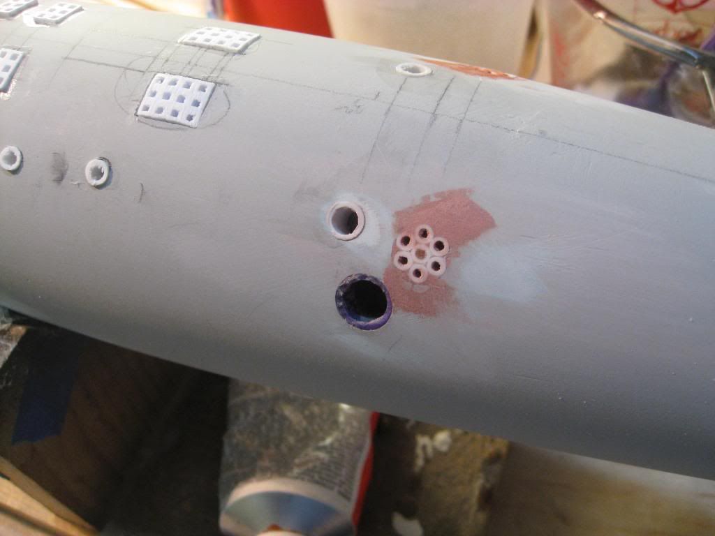
    For several years I've been researching this boat to build a display model. Why this boat? Well, my name is William Rogers and I live in San Ramon, CA. I graduated in 1966 from the US Merchant Marine Academy where my knick name was "Will" Rogers. I worked a few years at sea as a marine engineer and then in a shipyard but after visiting the USS Redfin in Baltimore many years ago, I was hooked on subs. Since then I’ve built several RC and display models but my goal has long been to model the "Willy R" as she was known to many. The plan is to build in 1:120 scale and represent as accurately as possible the detail I've researched. This will include such things as main ballast tank flood holes, main and aux seawater suctions and discharges, secondary propulsion motor and a host of other goodies.

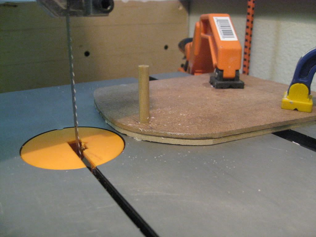
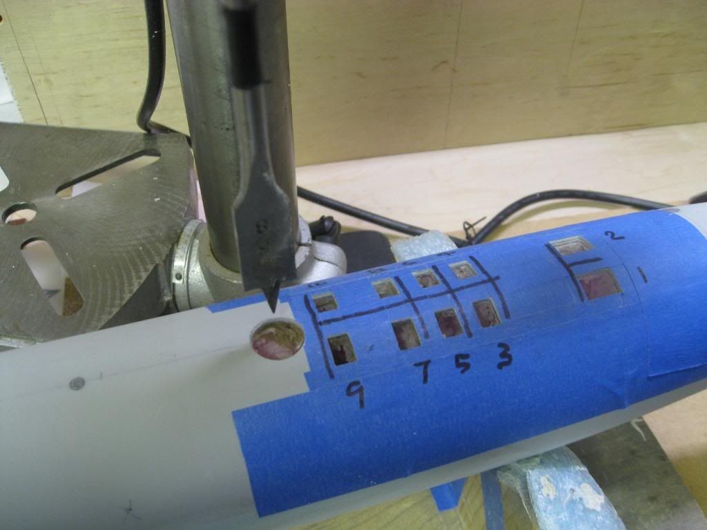
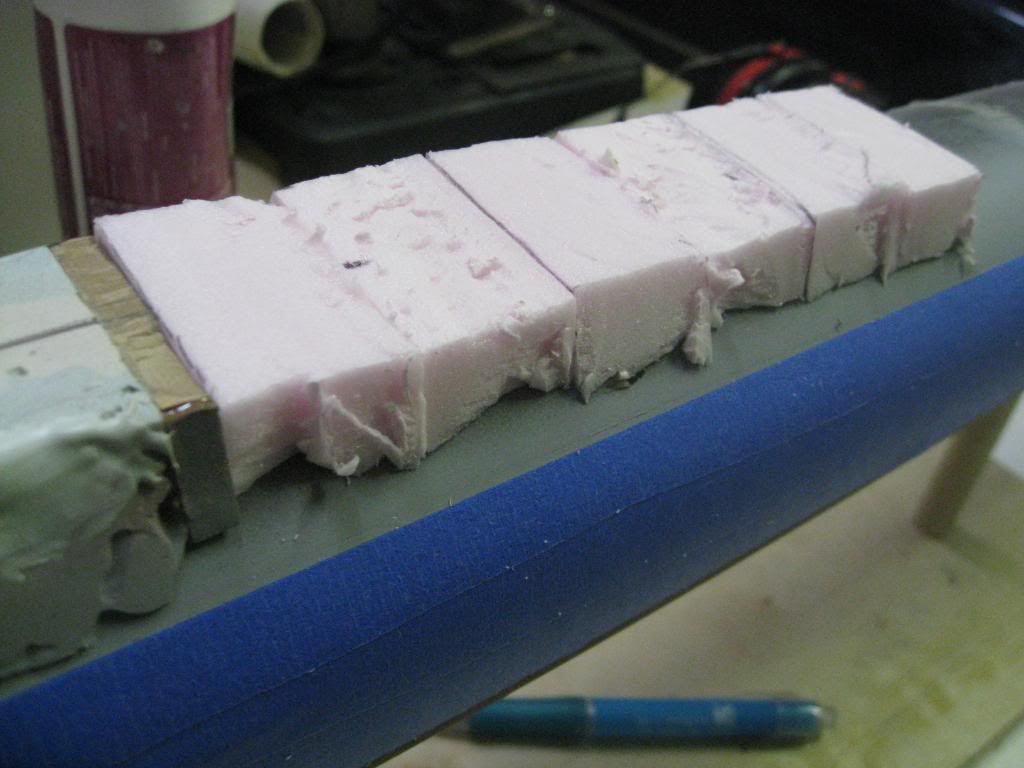
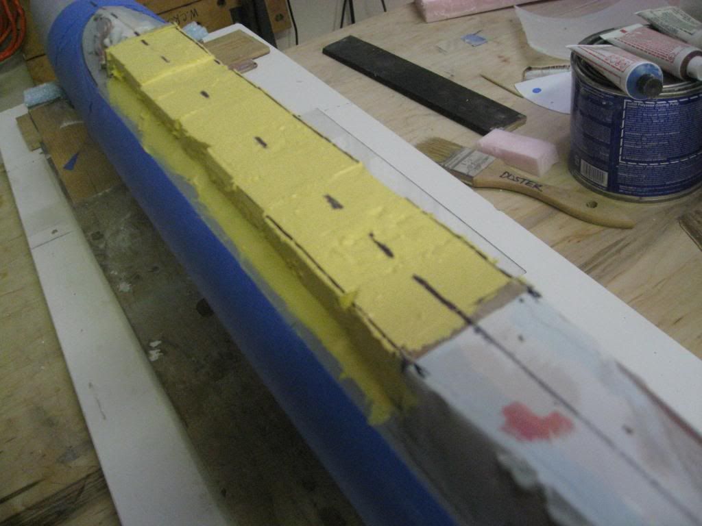
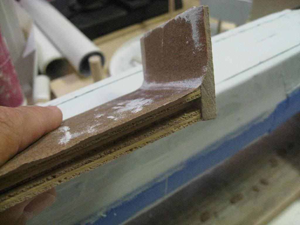
    Since I don't have a lathe, I decided to use pink foam as the hull reinforced by 1/4" all thread stock as the centerline axis. I'm using a drill press, bandsaw, sander, dremel, and several other hand tools. So, here we go.

    The first picture is my dust collector box set up at the drill press and connected to my shop vac.


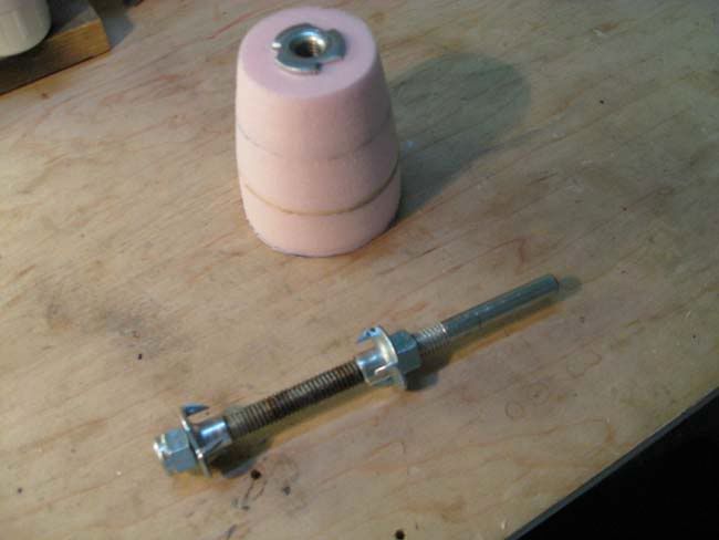
    Three rough circles of foam were glued together and mounted on the mandel for "turning" on the drill press using various grades of sandpaper glued to tongue depressors as the cutting tool.


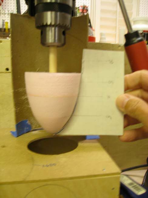
    This was the first attempt at shaping the bow. Note that I used a wooden dowel instead on the mandrel. After a few failed attempts to shape the bow in foam I switched to balsa for the final. The pink foam didn't hold up that well at the bow.


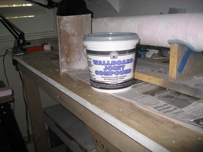
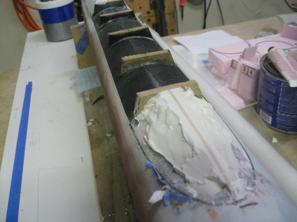
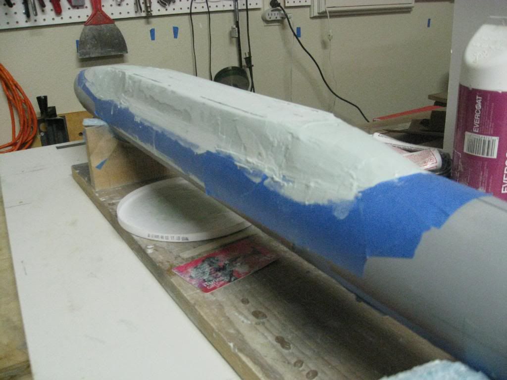
    For smoothing the hull I cut a mailing tube in half, glued sandpaper to the inside and used it to sand the wallboard joint compound after it dried.


    This is the hull nearing completion of the first step. Later I fiberglassed over the hull to add strength.
    [IMG]http://i345.photobucket.com/albums/p...nkFoamHull.jpg[/IMG]

    Since I'm also posting my build on the Subcommittee website, bear with me as I bring this thread current. At that point I'll post my progress simultaneously on both sites.

    "Will" Rogers
    SSBN659
    Last edited by SSBN659; 04-29-2010, 02:54 PM.
  • SSBN659
    Commander
    • Feb 2009
    • 405

    #2
    I should have mentioned earlier that I used the jig below to cut my pink foam circles on the bandsaw to form the hull.


    I thought this would work just fine but after fiberglassing the hull and checking for true I discovered my tapered stern was out of alignment. I tried correcting it by cutting out a wedge shaped section but that didn’t work at all.


    This was so frustrating that I threw out the whole thing and started over. This time I used a heavy duty mailing tube for the parallel midsection of the hull and cut most of the fore and aft tapers on the bandsaw tilting the table to the angle that gave the closest fit. This still required some wallboard joint compound for shaping. The 1/4” all thread and circular pink foam sections run through the mailing tube. After fiberglassing again the alignment checked out fine.


    Once the hull was where I wanted it, I started concentrating on all the underwater hull penetrations. I started on the underside because the finished model will be supported by two 1” diameter clear plastic rods and I had to layout the underside to see where to drill for the plastic rods.

    I’ve had in mind for some time that I want to model the Secondary Propulsion Motor in the deployed position but at a scale of 1:120 I wasn’t sure how it would work out. Here are some shots of the SPM, the work in progress and the final. I thought if it didn’t turn out well I would not do the SPM and just scribe in the cover door instead. I was happy with the way it turned out so the SPM will be shown deployed.


    "Will" Rogers
    SSBN659

    Comment

    • SSBN659
      Commander
      • Feb 2009
      • 405

      #3
      I mentioned previously that I wanted to layout the bottom details so I knew where to locate the clear plastic rods for supporting the model. Laying out the openings in pencil over the primed hull and the confirming their accuracy is necessary to avoid mistakes before cutting into the hull. The picture below shows the main seawater suctions and discharges port and starboard as well as number 4, 5 and 6 main ballast tank inlets port and starboard. The circle on the far right is where the after support will be located just forward of MBT #4.


      The forward MBT inlets as well as the anchor and other details are shown in the next picture. The forward support rod will be located just aft MBT #3 inlets. It’s important to remember the docking plan shows the hull as if you were inside the hull looking down. When laying out the details the hull is upside down so port and starboard orientation can be confusing. Note my crossed out marking forward of the anchor.


      Blue painters tape can be used for several different tasks. Here the tape is used to mark locations that were cut out for MBT inlet grates that will be installed later. A hole was drilled in the hull between the taped boundaries and the opening enlarged by filing up to the edge of the tape. The tape also protects the hull for those times when I might have otherwise scratched the hull by accident.


      Finally, here is where the hole for the forward support rod was drilled just aft MBT #3.


      "Will" Rogers
      SSBN659
      Last edited by SSBN659; 04-28-2010, 09:13 PM.

      Comment

      • redboat219
        Admiral
        • Dec 2008
        • 2735

        #4
        Would be nice if you can make an RCable kit of this.
        Make it simple, make strong, make it work!

        Comment

        • SSBN659
          Commander
          • Feb 2009
          • 405

          #5
          I thought about that briefly but with Engle's Lafayette and Lee Upshaw's Benjamin Franklin class models out there I don't see a need. Building this as a one of a kind display model for my office has been my goal for many years.

          "Will" Rogers
          SSBN659

          Comment

          • He Who Shall Not Be Named
            Moderator
            • Aug 2008
            • 12256

            #6
            Originally posted by SSBN659
            I thought about that briefly but with Engle's Lafayette and Lee Upshaw's Benjamin Franklin class models out there I don't see a need. Building this as a one of a kind display model for my office has been my goal for many years.

            "Will" Rogers
            SSBN659
            And an excellent effort so far. I like how you jumped back onto the saddle when the first hull attempt went bust.

            Ride 'em, Cowboy!

            David,
            Who is John Galt?

            Comment

            • SSBN659
              Commander
              • Feb 2009
              • 405

              #7
              We’re making progress on the under side hull openings. There are 16 openings in way of the missile tubes. At this point I want to publically thank the SC members who have been giving me help with information on this model. I especially thank Bob Harris, SC member and former crewmember on SSBN659 for telling me what these openings are. According to Bob these are for the tube breather valves that “…are part of the missile tube compensating and hovering/depth control system. During a ripple fire launch the birds are leaving to fast for pumping to compensate for the water weight gain so the muzzle door closes and the system blows the tube down to a predetermined level at which time the depth control system takes over for fine control.”

              So, having identified what they are, here’s how they are represented using styrene tubing.


              The holes were laid out and drilled. Then I CA’d short lengths of tubing in each opening. After looking at my documentation I decided the tube diameter was too large. I then glued smaller diameter tubing inside the larger tubes. At this point the tubing was ready to sand flush with the hull.


              Some touch up and fill in using a Bondo glazing putty was necessary. Note the tooth picks used to keep the Bondo out of the tube. After a final sanding with the tooth picks removed the hull was ready for red primer. But, there was more to do using the styrene before the red primer.


              The next step on the underside was to represent the Main Ballast Tank (MBT) grates. On a previous model I had used square brass tubing but found grinding down the brass left too many gouges in the hull that had to be filled and sanded. This time I went for 1/8”square styrene tubing which was easier to work with. First I taped around the opening to be drilled and filed to shape. There are 16 of these so it took some time to complete the openings. Several pieces of square styrene cut to about ¾” long were glued together to form the MBT grate as shown in the following picture. Also, this time I used more blue tape to protect the hull. In this picture you see the after MBT openings, some drilled, some filed, and one test grate to see how it would look.


              Satisfied with the look, I went on to complete the openings and assemble and install the remaining grates. They would still have to be filed flush with the hull and each tube had to be chased with a small tool to remove the burrs from sanding. What you see in the next two pictures are the fwd and aft MBT grates glued in place before sanding. Each opening was hand fitted to its particular grate.


              After sanding the grate the open gaps around the perimeter had to be filled and sanded. For this operation I used the blue tape to protect the grate openings and filled the gaps with red glazing putty. The same process was used to fill any gaps around styrene tubing used to represent the various circular water suctions and discharges.


              Finally, a rectangular space between MBT’s 5 & 6 was opened for eventual mounting of the Secondary Propulsion Motor (SPM). Although the SPM is complete, it won’t be installed until the model is just about complete.

              "Will" Rogers
              SSBN659

              Comment

              • SSBN659
                Commander
                • Feb 2009
                • 405

                #8
                Work on the topside has taken much longer than I thought it would. It would have been easier had I been working from a detailed set of cross sections for the superstructure but I’ve not been able to find any. So, with several pictures of SSBN’s of this class and Outboard Profile and Main Deck drawings I set out to shape the superstructure as best I could.

                My plan was to cut pieces of 3/16” scrap MDF to shape, glue them to the hull along the centerline and use Plaster of Paris to rough in the shape. BIG MISTAKE! Yes, the material was cheap but not easy to shape when wet and a bear to sand not to mention the mess. So the solution was to start over using a polyester glazing putty called “ Easy Sand” by Evercoat.

                This shot shows the aft end of the superstructure as I began to chip away the Plaster of Paris.


                After roughing in the aft end I glued some pink foam filler pieces in place to start shaping the missile deck. The foam was painted with some left over latex paint to prevent the polyester putty from attacking it.


                Here you see the beginnings of my “Yellow Submarine”. You can also see the roughed in fore and aft ends of the superstructure with the centerline and main deck tangent lines layed out with a black “Sharpie”. Finally, you can see how I’ve used blue painter’s tape to mark the intersection of the superstructure with the hull.


                At this point the rough in is covered with Evercoat “Easy Sand” and the superstructure is ready for sanding and shaping. But how to get the correct shapes?


                In my research I was able to find several pictures on the web to help me with the shapes. Following are some of them. The first is the Casimir Pulaski on drydock followed by the Francis Scott Key, both showing the forward end of the superstructure.


                Next are after end shots of Kamehameha and Andrew Jackson.


                Using the shot of Casimir Pulaski I estimated the angle between the side of the superstructure and the vertical somewhere between 15 to 20 degrees. I split the difference and made a tool for sanding the curve at the main deck tangent line as well as the side.


                If anyone out there knows for sure what the angle really is, I’d like to know just for the heck of it. Meanwhile, back to the workbench for some more sanding and shaping.

                “Will Rogers”
                SSBN659

                Comment

                • SSBN659
                  Commander
                  • Feb 2009
                  • 405

                  #9
                  In my attempt to bring this post current with what I've posted on the SC website I realized I forgot one very important step on the underside of the hull. Sorry about that. Here's what I left out before going topside.

                  Now to some really interesting stuff. In my research I found the following picture showing one of the Forty-One For Freedom on drydock. Having worked in a shipyard I immediately recognized the main condenser cooling water suction and overboard discharge because of their large diameter openings. The intake has a grate to prevent large objects from being pulled into the main condenser cooling water pump suction. What I didn’t understand was the discharge that had 6 smaller diameter openings.


                  Here’s what I found out from David Meriman (thanks Dave, you’ve always been very helpful).

                  “The MSW condenser discharge disgorges relatively 'hot' (thermally, not nuclear) water -- stuff that leaves a significant IR signature. Soviet satellites are one means of scanning our patrol areas looking for IR 'anomalies'. Bad Ju-Ju!

                  The many holes at the single MSW discharge (there are two, one each side) are intended to get the hot water mixed in with the ambient 'cold' water as quickly as possible to negate the sharp IR image that would result if the water was discharged in one big stream -- pretty much like how the F-117 exhaust is quickly mixed with the ambient air to attenuate its IR signature.”


                  So, with that information I represented the discharge using my styrene tubing as shown below. I’ve also included the auxiliary cooling water suction and other openings.


                  This was my attempt using plastic screening for the grate on the cooling water suction. I wasn’t happy with the way it looked and scrapped that idea. I found some brass material in a train hobby shop that I think will work out much better and I’ll work on that later.


                  The next three shots show the primed bottom side opening starting aft and moving forward. I’ll scribe in the anchor outline and a couple other manhole covers before going to work on the topside.


                  That's it, you're now current.

                  "Will" Rogers
                  SSBN659

                  Comment

                  • He Who Shall Not Be Named
                    Moderator
                    • Aug 2008
                    • 12256

                    #10
                    No. The breather-valves hung off the sides of the mount tubes, mid-level Missile Compartment. These were internal, but still an element of the complex and massive, 'missile compensation system'. I was a Launcher Tech aboard the DANIEL WEBSTER (SSBN 626) for nine patrols. Trust me on this.

                    The sixteen big holes, one under each tube, are the missile compensating ball-valves. A ball-valve rolled open and then shut in a precisely timed fashion shortly after a launch. The ball-valve worked, in conjunction with the breather-valve (three or four solenoid types, depending on the particular boat ... God! I still remember that ****!?), to quickly blow overboard a specific fraction of the back-flooding water that filled a tube soon after 'missile-away' was indicated at the LCP. One job of the missile compensation system was to manage the amount of back-flood water in a fired tube in order to maintain some semblance of trim during a missile launching event.

                    So, what you're representing on the bottom of your models hull are missile compensating system missile tube ball-valve openings. Nothing to do with breather-valves.

                    I had to grease those damn balls periodically. That necessitated first having to get access to the ejection chambers of all the tubes from lower-level Missile Compartment, below the deck plates. Hello, two-man rule! Then, to install blanking plates atop the valve bodies (just feet below the first-stage nozzles of the A-3's we carried, a tight fit for two idiots with wrenches and a flashlight) in the chamber. Only after the blanking plates were in place were the Divers turned loose to smear handfuls of grease onto a ball valve, scooting back, and waiting for the weapons guys to roll the ball, and eye-balling its operation. Timing was everything or they would wind up calling you 'stumpy'.

                    I was one of the two boat Diver's attached to the Webster's Blue-crew. And unlike other Boomer's, our Weapons and Engineering divisions made good use of us.

                    David,
                    Who is John Galt?

                    Comment

                    • Kazzer
                      *********
                      • Aug 2008
                      • 2848

                      #11
                      Originally posted by Merriman
                      I was a Launcher Tech aboard the DANIEL WEBSTER (SSBN 626) for nine patrols. Trust me on this.

                      I had to grease those damn balls periodically.

                      David,
                      Any photos of this event?
                      Stop messing about - just get a Sub-driver!

                      Comment

                      • He Who Shall Not Be Named
                        Moderator
                        • Aug 2008
                        • 12256

                        #12
                        Nobody likes a smart-ass!

                        David,
                        Who is John Galt?

                        Comment

                        • Kazzer
                          *********
                          • Aug 2008
                          • 2848

                          #13
                          Originally posted by Merriman
                          Nobody likes a smart-ass!

                          David,
                          Moi? Oh! My sides hurt - again!
                          Stop messing about - just get a Sub-driver!

                          Comment

                          • SSBN659
                            Commander
                            • Feb 2009
                            • 405

                            #14
                            David, Thanks for the correction, interesting stuff. With your information and a bit more research I understand what you said about the ball valves. Greasing them underwater by hand took a lot of "brass".


                            "Will" Rogers
                            SSBN659

                            Comment

                            • SSBN659
                              Commander
                              • Feb 2009
                              • 405

                              #15
                              I posted the Hovering & Depth Control diagram thinking it was part of the missile compensating system David told us about earlier. Now, after reviewing it again, I don't think so. So back to the work bench.

                              "Will" Rogers
                              SSBN659

                              Comment

                              Working...