
David,
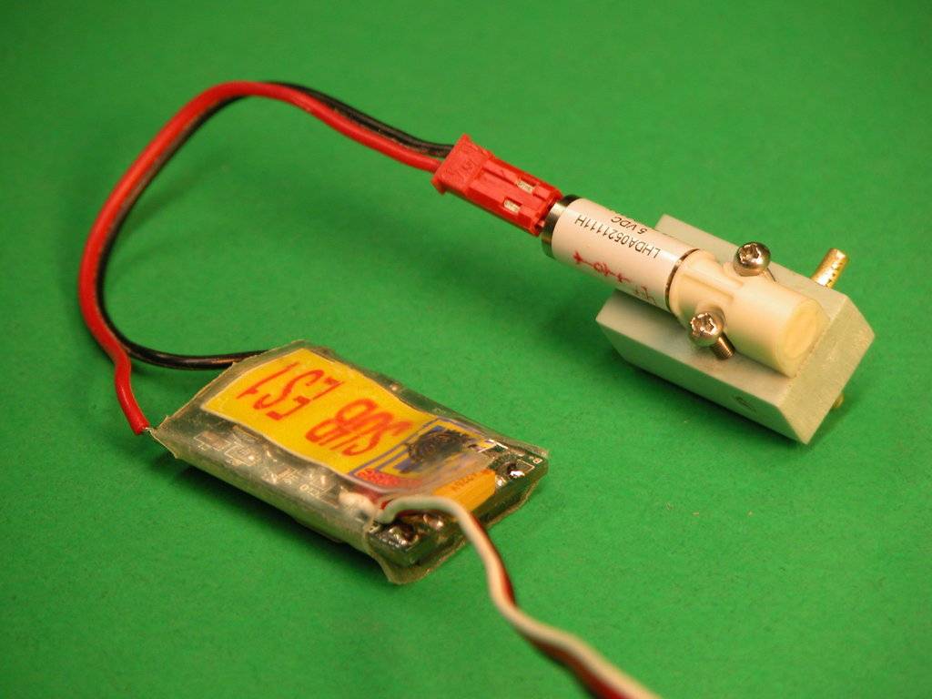
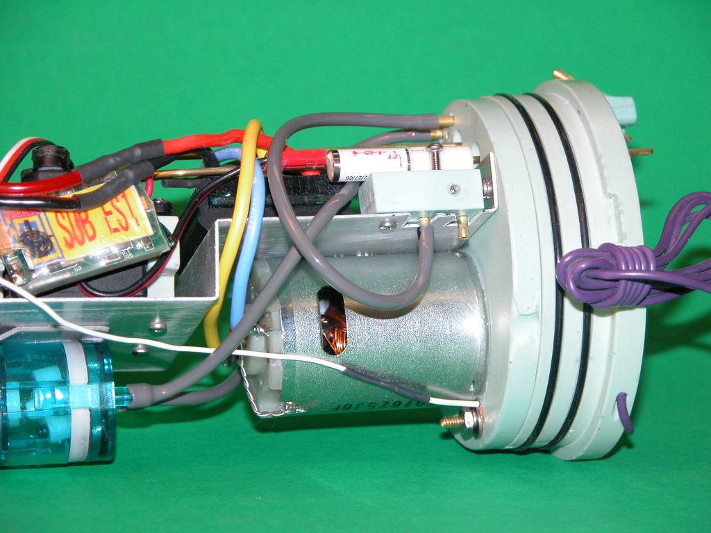
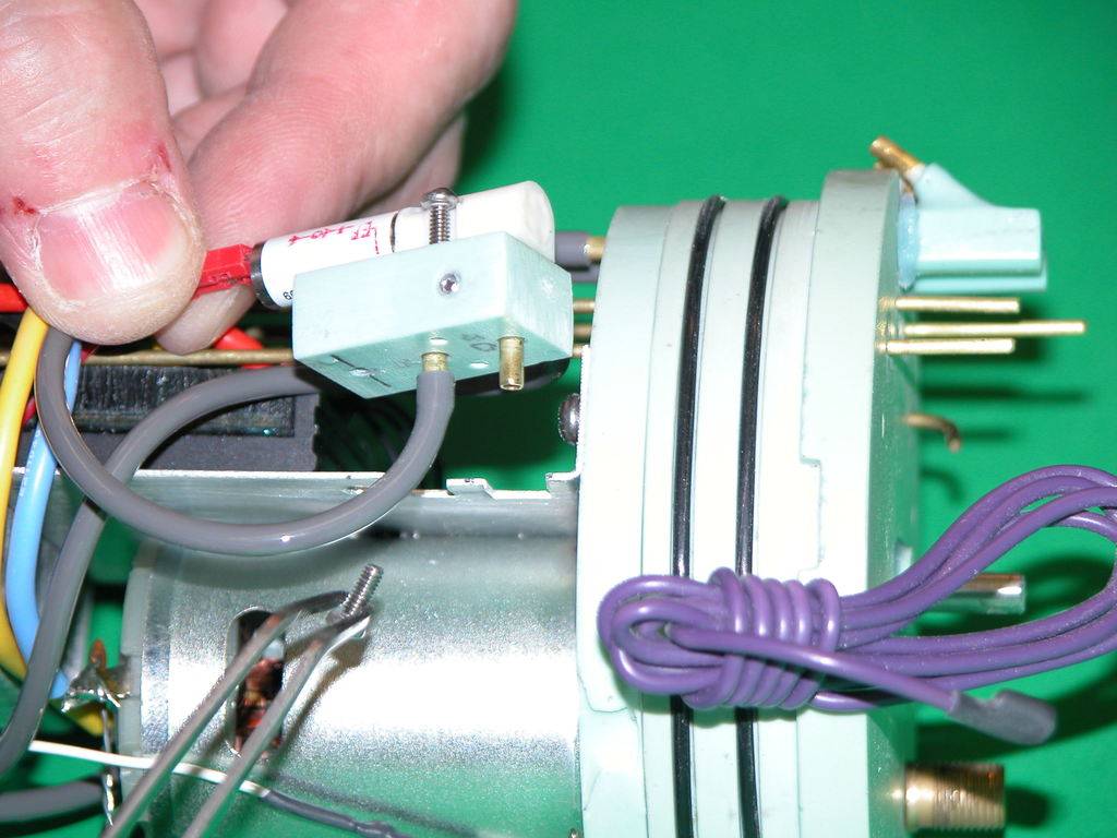
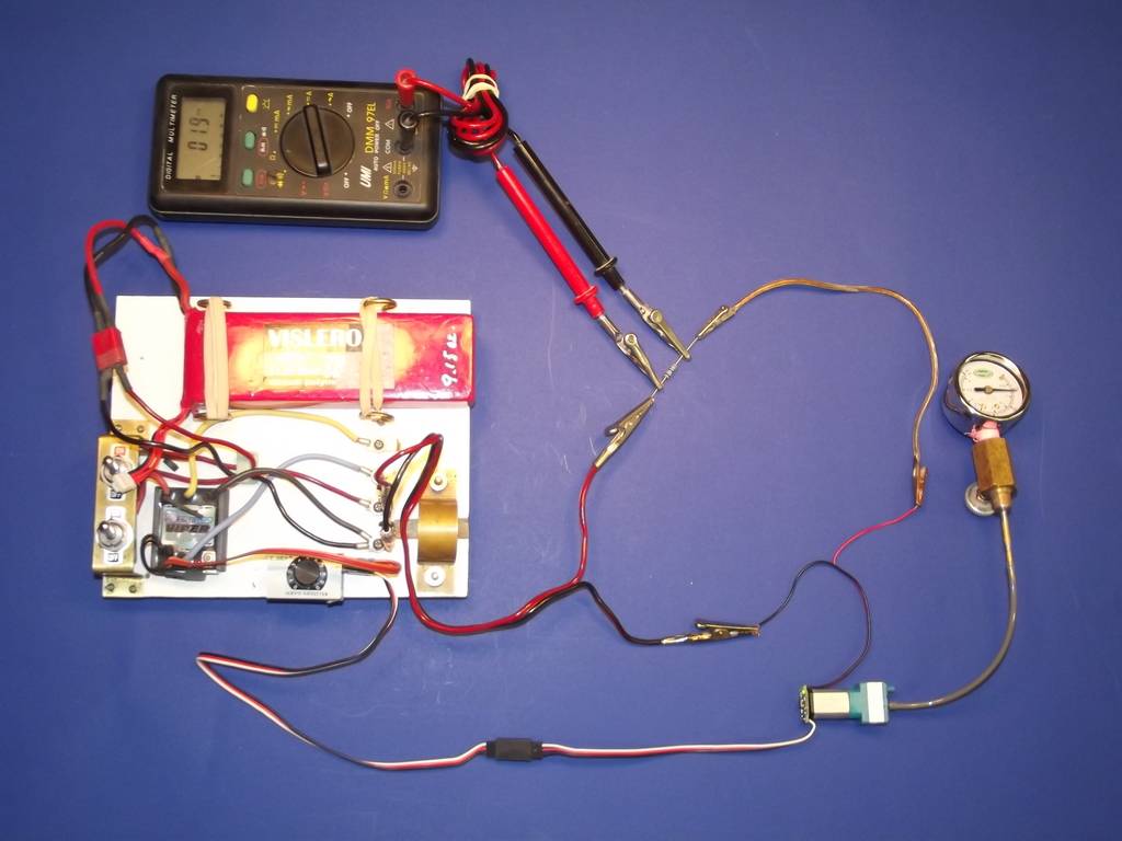
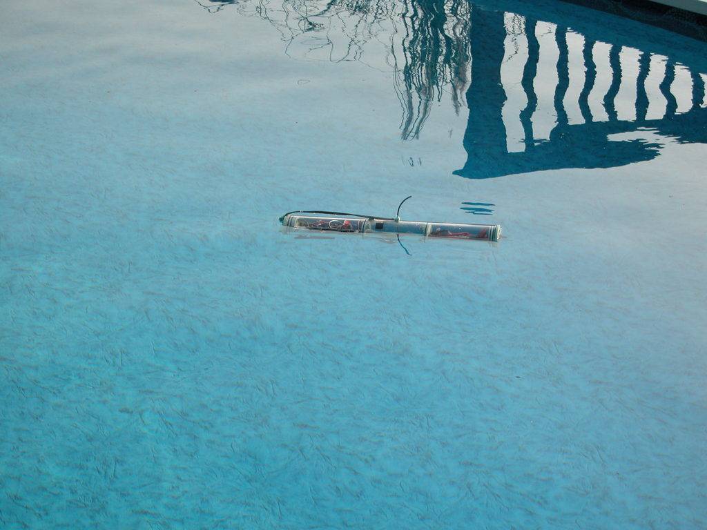
do you still have a copy of the article or photos of your initial semi-aspirated system, the one were you used those mini pneumatic valves?
do you still have a copy of the article or photos of your initial semi-aspirated system, the one were you used those mini pneumatic valves?


Comment