-
Would be possible to get the following Type IX fittings; Resin fore and aft diveplanes, rudder mechanism, drive shafts, bearing mounts, dogbones, props and magnetic hold downs?Last edited by redboat219; 03-03-2024, 09:05 PM.Leave a comment:
-
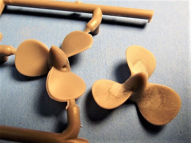
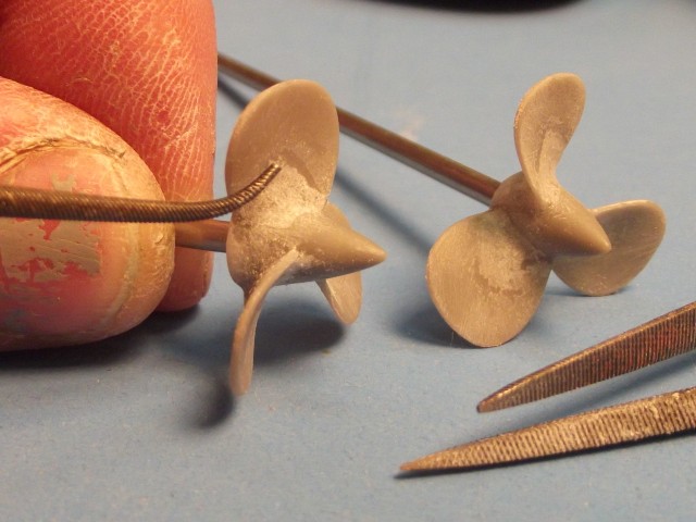
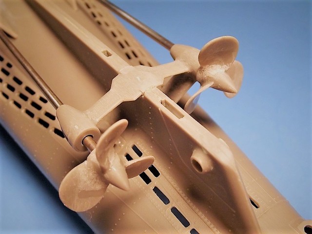
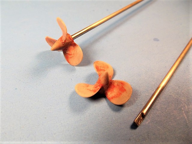
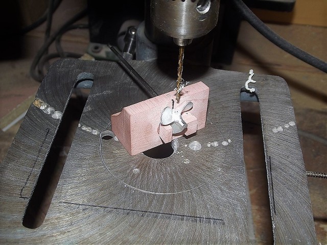
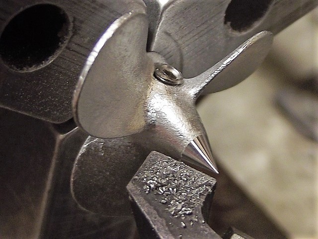
Same diameter as the kit wheels. I extensively re-worked the kit propellers to eleminate the injection process artifacts that spoiled the taper of the edges and the blade-to-hub fillets on one face of the blades. I used the corrected wheels to make a rubber tool from which I produced white-metal castings that became an element of our fittings kit.
DavidLeave a comment:
-
-
-
To be statically stable (tits down, not tits up) on and beneath the surface a vehicle must be dense down low, and less dense high. We pack dense material into the hollow keel area, lead is a reasonably dense material that is (relatively) cheap and workable. We pack high-volume, low weight (read: un-dense) material up high, but no higher than the designed waterline.
Center of gravity low; center of buoyancy high.
Ten-ounces of lead fixed ballast weight in the keel trough, and an approximate amount of foam up high hanging off the sides of the superstructure to displace at least ten-ounces of water. This is the initial load-out of fixed ballast weight and foam -- things will get fine-tuned later.
Always do the hard stuff first. In this arena the hard stuff is cramming foam between the installed SD and inside vertical surfaces of the superstructure. But, here's where the foam installation can help you: if you find that the port and starboard sides of the superstructure are bowed in too much, you can work the fit of the foam to push against the SD and push the superstructure out to where they should be. This can be a big deal as you will later install deck railing that could be damages by the deck pieces when they pop out of a badly sprung superstructure. Work the foam job right and those deck pieces will match the opening in the superstructure.
Here you see some of the tools and consumables used to work the foam blanks: round and flat sanding blocks, knife, Sharpie pen, and Permatex Gasket-Maker (the blue RTV adhesive).
You start with foam blanks. Pink or blue insulation foam. It's polystyrene, but the big deal is this: it's of a closed-cell structure .... it won't water-log on you! Don't use the white stuff -- it's open-cell and will take on water like a sponge over time, ruining your initial trim.
Start out with a half-inch thick sheet of the stuff, then strip it into a few two-inch strips, and cut those strips into three-inch long blanks.
All blanks are roughed out on the inboard side to a concave semi-circle with a one-and-a-quarter-inch radius (2.5" diameter cylinder ... duh!). Start at the center of the SD. Sand in a cursory convex curve where the foam meets the superstructure-hull. Each set of foam blocks is unique, owing to the tapper of the hull. As you work them to a tight fit make sure that each foam block is oriented so that the top face of each is even or no more than 1/16" lower than the bottom of the big limber holes running along the sides of the superstructure. This puts the buoyant foam just below the designed surfaced water line.
Periodically, as you complete the rough sanding of a foam block set, install it, and test fit the deck pieces to the superstructure. Keep shaving the outboard faces of the foam pieces till the deck sits properly on the superstructure flanges. Repeat for the rest of the foam blanks.
Work out how you're going to get the fixed ballast lead into that keel. You want ten-ounces of lead in there. Work it out! Insure none of the fixed ballast weight does not make contact with the bottom of the SD. It matters not a bit if the led is sheet, like what I'm showing; bar-stock; bird-shot; inlay strip; car tire balancing slugs; cast to suit; gravity model car weights; stained-glass lead wire; or transmuted waste from the Hanford B-reactor ... I don't care! Ten-ounces of lead.
You're going to give up a whole day to it, but when you're done, the foam pieces girdling the SD will push the superstructure out just enough to make installation of the deck pieces an easy operation.
Once you have them sanded to fit properly, mark the location of each foam piece onto the superstructure, and pull them out. Remove the SD. Finally, using Permatex RTV adhesive, bond the floatation foam within the superstructure.
Note that installation of the lead fixed ballast was deferred until all the foam work had been done -- as the foam fitting is a very labor-intensive process, necessitating extensive handling of the model hull, why burden yourself by making the model unnecessarily heavy with installed lead? So, with the foam pieces in place, your next step is to install the lead. More Permatex RTV adhesive.
MAttached FilesLeave a comment:
-
-
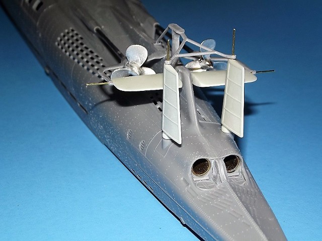
The Caswell-Merriman SAS Sub-driver (SD) -- the system that propels, controls, and manages ballast water --- makes use of a Semi-ASpirated ballast sub-system which requires a float operated induction valve (head valve) mounted within the model submarines sail. Here you see the snorkel mechanism (of the horizontal type) next to the 1/72 Type-9's sail. It's the job of the snorkel head-valve to open up to atmosphere only when the valve is above the water's surface. When underwater, the valve is closed, preventing a potential flooding path into the SD's interior.
The horizontal type snorkel mechanism has to fit within the sail, with care being taken to insure that the float and attached float-arm are not obstructed by any of the SD items projecting slightly into the sail. For that reason it's vital that you place the SD within the hull as I've outlined! Note that the inlet nipple on the SD's four-point manifold is well forward, clear of the snorkel mechanism. This is where the snorkel induction hose hooks up to the sub-systems induction line.
The horizontal type snorkel is used on low, wide and/or long sails -- as a general rule, submarine model depicting subjects built before the cold-war era. The vertical type snorkel is used on tall, narrow and/or short sails. Both the horizontal and vertical type snorkel mechanisms serve the same function: to isolate the induction line against water entry once the sail goes underwater. With the snorkel head-valve closed (underwater) the SAS ballast sub-system will draw blow air from the Sub-driver dry spaces until the model either surfaces (where the snorkel head valve opens, admitting air to the SD), or the pump stalls due to the high vacuum created.
This shot will help you understand how the snorkel mechanism fits within the sail . Also note that I've taken the added step here to provide optional snorkel mechanism mounts -- these permit me to quickly install and remove the mechanism should the need arise. Normally, you're fine tack-gluing the three legs of the mechanisms foundation to the underside of the gun-platform deck. Note that in this arrangement I've run the snorkel induction hose around the float and float arm with a fairing tube -- this insures the hose will not jam the mechanism by getting under foot, which would preclude the SD getting surface air when the sail broaches the surface, failing to break the vacuum within.
The sail connects, system wise, to the SD through the induction hose that runs between the snorkel head-valve and SD four-point manifold -- it's at this manifold that air is either taken to blow the ballast tank from atmosphere (through the snorkel) or from the dry spaces of the SD itself (through the safety float-valve, explained later).
Note that the stock foam float has been trimmed a bit with sandpaper to conform to the tight confines under the sails bridge deck. Also note that a short length of 3/32" o.d. brass tube is used as a connection point between sail and the rest of the model.
This is how things should look as you set the sail down onto the deck: the snorkel induction hose well forward and, as you lower the sail down upon the deck, the slack in that hose tucked within the annular space between the SD and deck.
Unless you are running coaxial cable up the periscope to feed a 2.4gHz r/c systems antenna, the induction hose is the only system related connection between sail and SD.
This SAS ballast sub-system mock-up will give you an idea of how the snorkel relates to the rest of the SAS type ballast sub-system (this particular snorkel mechanism is of the vertical type): air to blow the ballast water out of the ballast tank comes either from atmosphere -- through the open snorkel head-valve; or the air is scavenged out of the dry spaces within the SD through the safety float-valve).
That brass bottle is the safety float-valve -- its job is to prevent water within the flooded induction line (an abnormal condition, and real bad Ju-Ju) from getting into the SD's dry spaces.
The safety float-valve and snorkel head valve constitute the 'two-valve protection' I learned to embrace as a qualified submariner. Two-valve protection... don't leave home without it!
And here is a practical example of the relationship of the snorkel mechanism (in this case a vertical type, not the horizontal type used with the Type-9 model) to the other elements of a typical SAS equipped SD.
If you are interested in a detailed presentation of the SAS type ballast sub-system now employed by many of our Sub-driver's, I invite you to down-load and study the document found here:

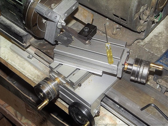
With the SD secured within the hull you need to make the external pushrods (that make up magnetically to the SD's internal pushrods) that actuate the rudders, stern planes, and bow planes. Study the above photo. As you can see, all you need are lengths of 1/16" diameter brass rod, and our magnetic couplers. All points of contact to the pushrods (with the exception of the rudder bell-crank) were secured with the magnetic couplers. The pushrod-to-rudder bell-crank connection was made through the more traditional Z-bend union. But, there is no good reason why that connection could not also have been achieved through the use of a magnetic coupler.
With the SD firmly indexed to the model there is no possibility of a shift of SD position, which would throw all linkages out of alignment. For the sake of simplicity, elimination of linkage back-lash, and ease of installation/removal, almost all unions between pushrods and SD and bell-cranks is done with magnetic couplers. We all have Brian Stark to thank for this innovation.
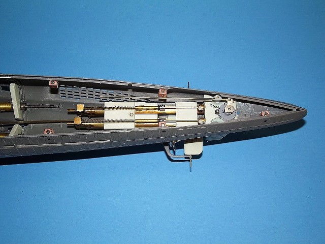
And here is an example of what the more traditional form of pushrod-to-bell-crank connection looks like. I employed the classic Z-bend to the after end of the rudder pushrod. The pushrod directly making contact with the bell-crank. I will later change this out by installing an iron machine screw into the hole of the bell-crank and outfit the after end of the rudder pushrod with a magnetic coupler -- which will make it look very much like what you see now in the lower stern plane coupling of magnet-to-iron bearing machine screw of the stern plane bell-crank.
Pushrod shape and length is driven by distance-to-SD coupler, and relative height of control surface bell-crank to SD magnetic coupler position, i.e. the pushrod for the rudder is a short, straight shot between SD magnetic coupler and rudder mechanism bell-crank; the stern plane pushrod, on the other hand, couples to the SD high, but must meet the very low mounted stern plane bell-crank. Hence the radical bends along the length of the stern plane pushrod.
The bow plane linkage, as you would expect is simple: the pushrod pushing and pulling on the bow plane operating shaft bell-crank. There is enough magnetic force to assure a non-break union between magnet and iron screw under normal conditions. However, it's a union that will part when pulled by hand or if the planes are subjected to a shock-force, such as would be encountered in a collision or rough handling. Such 'shock-absorbing' unions in the control surface linkages work to isolate the SD servos from gear-stripping loads.
MLeave a comment:
-
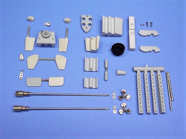
An SD securing foundation with attached Velcro strap. Next to it are the parts as they arrive with the 1/72 Type-9 fittings kit. You'll have to come up with the indexing pin round stock.
Grind away the right-angle portions of the keel well to fair the Velcro strap around the SD at the base. And while you're at it, grind away, at their bases, the radial indexing flanges molded within the hull that would have embraced the un-used hull bulkhead pieces -- these would otherwise keep the SD from getting as low into the hull as possible.
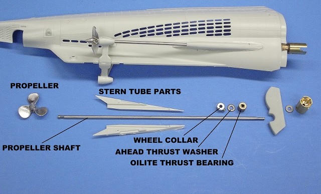
You will index the SD to the hull using the Dumas dog-bones as a guide: you drop the SD into the hull, slide it fore and aft as you engage the two dog-bones into the propeller shaft couplers and SD drive shaft couplers. Once the dog-bones are engaged and hard up against the propeller and SD shafts, move the SD forward 1/16" to give a little clearance. Hold it there and mark the hull where the 1/8" SD indexing hole is (at the bottom of the SD's ballast tank). Glue the SD foundation within the keel well so that it's indexing pin is in alignment with that mark. The indexing pin secures the SD from longitudinal and rolling movement. The Velcro strap keeps the SD from moving vertically.
Before gluing the magnet foundation to the superstructure you first round-file an indentation in the rail-like superstructure flange. This half-circle indentation affording clearance for the outboard portions of the deck magnet.
You want to provide three pairs of latching magnets to the forward deck piece; two pairs of latching magnets to the after deck piece; and four or five pairs of latching magnets to the center deck piece. At the two breaks between the three deck pieces place two sets of latching magnets no further than 3/4" from the break. Mark with pen or pencil on the outside of the superstructure where you intend to position the foundations -- consider what, if anything, will get in the way later and adjust accordingly.
.... I failed to do this with the after deck piece, finding later that the aft set of magnet foundations interfered with operation of the rudders. So, those had to be busted loose and repositioned. Check twice, glue once!
As the angle of the superstructure sides vary over the length of the hull you will select a foundation that suits that angle. If you find that none of the supplied foundation blanks account for a particular angle, then take the blank with the most extreme angle to its face, cut out the foundations you need, and grind its face to match the station on the superstructure it will be glued to.
You'll use thick formula CA to adhere the magnet foundations to the inside of the superstructure. This glue cures slowly -- giving you time to move the foundation up and down until the attached deck magnets upper face is about .010" above the superstructures deck mounting flange.
Leaving the deck magnet still atop the superstructure magnet you lay down the deck piece and push down on it till the bottom of the deck makes contact with the superstructures flange. While you did that the friction-fit magnet in its foundation bore slid down the required amount, placing the upper face of the deck magnet exactly in the same plane as that of the flanges upper face. In this condition the deck sits on the superstructure flanges and the latching magnets are as close together as you possibly could get them.
You then drop a 'finder' magnet atop the hull. This finder magnet permits you to identify the position where the deck magnet will be glued to the bottom of the deck piece later. As best you can, use pen or pencil to circle the finder magnet.
This is rather sloppily done by tracing with pencil or pen around the 'finder' magnet -- all that good high-relief detailing atop the deck makes marking-out a chore. Now you see why I don't advocate simply punching holes into the deck to inlay the deck magnets -- doing so would ruin all that fine looking detail on the deck pieces.
Once you've seated a superstructure magnet, you remove the deck, pull the deck magnet off the superstructure magnet and set it aside for later cleaning and abrasion -- steps that prepare it for gluing to the bottom of the deck piece.
A neater alternative to the pen or pencil marking is to punch out holes in pieces of masking tape and to place the tape around the 'finder' magnets. The holes in the tape, stuck to the top of the deck piece, indicate where to put the 'finder' magnets when it comes time to glue the deck magnets to the underside of the deck piece.
And here is a properly seated superstructure magnet -- the distance between its face and the top of the superstructure flange about equal to the thickness of the disc-type magnet. Exactly the distance below the bottom face of the deck piece the mating face of the matching deck magnet will be with the deck sitting on the superstructure flanges.
Temporarily pull the deck magnet away from the superstructure magnet. Soak in lacquer thinner, wipe clean then sand, with #400 sandpaper the edge and face of the magnet that will present to the underside of the deck. Reinstall the deck magnet to the superstructure magnet.
The cleaning and abrasion will facilitate a tight glue bond between deck magnet and deck.
A finder magnet, through magnetic attraction, holding a deck magnet in correct position preparatory to gluing the deck magnet permanently in place.
On the bottom face of the deck piece, where deck magnets will go, rough up the surface with #240 sandpaper. With a deck magnet properly positioned with the aid of a 'finder' magnet, lay down some thin formula CA adhesive and run the glue around the perimeter of the disc-shaped magnet. But, minimize glue build-up to the outboard edge area of the deck as it would interfere with a proper fit between deck and superstructure. Once you have a healthy puddle of glue down, hit the mess with a sprits of accelerator. Wait a few seconds and build up more glue to the inboard areas of the magnet to achieve a fillet between magnet and deck.
Don't forget to dab a small amount of thin formula CA around the superstructure magnet. This easily done by laying a drop of the glue to one of the channels previously cut into the upward face of the foundation, leaving it to capillary action to get the glue to every contact point between magnet and foundation.
The three-piece deck, through fortunate accident, works out for us: The forward section can be separetly opened up to gain access to the SD mission switch. This means you don't have to pop the entire deck to perform the simple function of turning the system on and off. It also gives complete access to the removable bow torpedo tube nest should you incorporate that feature. Through this opening you also get access to the bow plane linkage.
The removable stern section presents the rudder mechanism, stern plane linkage, and after torpedo tube nest should you install the weapon system.
The after set of magnet foundations you see here was a wrong move on my part, as they interfere with the later installation of the rudder mechanism. Fortunately, a quick twist on the foundation with a pair of pliers (what do you call two Filipino Aviators?... never mind) easily breaks the weak-in-shear-and shock cyanoacrylate adhesive used to bond the foundations to the superstructure. The foundations moved aft a bit, which worked to clear the rudder mechanism.
The end-game is a sail, three deck pieces and superstructure that attach to one another exclusively through magnetic force -- no other fasteners are required nor employed. This makes for an r/c submarine that is easily accessed, but whose access points are securely held together without need of unsightly screw heads.
Leave a comment:

Leave a comment: