
Thats the one. I'm pretty sure it's a polyester base too. It is a tiny bit grainy but one of the best advantages over most other bogs & fillers is you can vary the dry time by adding more or less hardner. Generally in a teaspoon size lump I will only mix in between 1 - 2 match head size drops of hardener to get a light salmon colour mix which gives me a bit of work time with the stuff so I can gently sand it or use a hobby knife to shave & shape it. Like most two part stuff it gets warm when curering but so far it hasn't shown me any ill effects on any models or plasticard I use and it seems to work well on fibre glass too.
-
Cheers,
Alec.
Reality is but a dream...
But to dream is a reality
-
A cylindrical template blank is made by laying up two laminates of 10-ounce fiberglass cloth over a waxed section of cylinder and saturating the weave with epoxy resin, as illustrated below.
I employ this GRP, tube shaped templates to guide me as I lay-out the hole pattern unique to the specific type Sub-driver Lexan cylinder undergoing manufacture.
First, a mock-up of the internals of the ballast tank -- the area of the cylinder that receives the most attention as to screw-fastener and other type holes -- is assembled, then used as the pattern off of which I loft the locations of the holes onto the template, then drill out the holes. The template is then ready for lay-out work in support of series production of Sub-driver cylinders, such as this 3" SD intended for use aboard the 1/60 ALBACORE model kit.
Who is John Galt?Comment
-
John Slater
Sydney Australia
You would not steal a wallet so don't steal people's livelihood.
Think of that before your buy "cheap" pirated goods or download others work protected by copyright. Theft is theft.
sigpicComment
-
Remember what polyester resin does to expanded polystyrene foam? Automotive fillers are mainly polyester resin and talc. It should key in well to styrene hulls, although it probably has very different expansion rates, and very little flexibility. You can purchase special polyester putties that the car trade use for filling imperfections in car bumpers, which are all plastic these days. These fillers are extra flexible, and I think they put some extra chemicals in to give the filler some extra bite on the plastic.
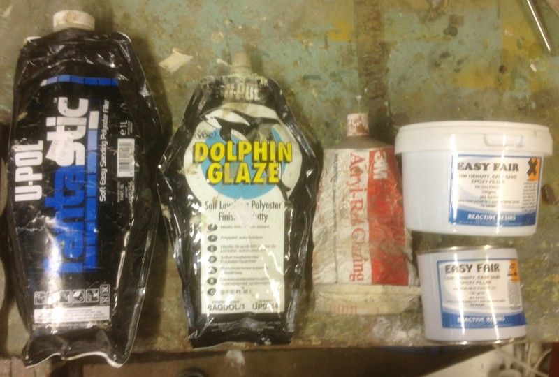
As per usual I can only recommend the trade names that are available here in the Uk. Can't go wrong with Upol. http://www.u-pol.com/product-cat/167...r-plastics.htm
I personally work with GRP hulls, and have now standadized on three fillers- Upol Fantastic, Upol Dolphin Glaze and Reactive resins Easy fair. The latter is a epoxy filler than behaves very similar to polyester putty, but is totally waterproof and very strong when cured. It doesn't spread quite as well as polyester filler, but comes close, and it takes much longer to try, so not so good for touch work.
The Upol fillers I use come in foil lined plastic bags, a bit like big toothpaste tubes. This makes dispensing the product much easier than the big tins this stuff normally arrives in, and helps keep the filler fresh.
Comment
-
David's excellent thread "a day in the cave" has answered a lot of questions,
David as you have kindly completed my order and have parts in the mail, I'll be starting Albacore soon.
Was wondering if you could tell me at what points along the hull you glued into the lower and upper hull halves the bulkheads / WTC saddles that come with the kit. My instructions that came with it make no mention of the proper position of these.
These pieces are shown below:
i.e. e.g - from David's thread "A day in the cave" (page 4)
Also what are the tab pieces along the lower sides of the upper hull?
Thanks
JohnJohn Slater
Sydney Australia
You would not steal a wallet so don't steal people's livelihood.
Think of that before your buy "cheap" pirated goods or download others work protected by copyright. Theft is theft.
sigpicComment
-
Bulkhead position was established simply by moving a bulkhead within the hull till it fit. It was then glued in place with a solvent type cement. Simple as that. After the glue set I placed the SD so the center of the ballast tank was at the center of the hull and cut back on portions of the bulkheads that got in the way.
The rounded edges of the upper and lower hull were roughed up with #100 sandpaper then coated with Bondo and brought to a knife-edge with sanding blocks and lots of bad words. The Bondo (actually Evercoat automotive body filler ... you know what I mean!) was then coated with thin CA that permeates the porous material and both hardens it and firmly bonds it to the underlying plastic hull.
MWho is John Galt?Comment
-
Thanks David
One thing I need assistance on with this build is the position of those side limber vents (square holes) and the bow planes. The plan I received with the hull is around 4" too big for the model, and the limber holes as shown on the plan are a tad confusing. Can I ask..
If you took a flexible ruler (curved to match the hull contours) and measured up at right angles from the bottom of the upper hull half;
how high up the hull half would the bow planes be located vertically?
how high up the hull half would the mid point of the section of square holes be adjacent the sail?
how high up the hull half would the mid point of the section of square holes be above the bow planes?
how high up the hull half would the last (most rearward) square hole be?
Only other question I have is - is the dorsal rudder that you have the latter larger one, or the early one which was 1/12th the chord of the sail?
Thanks
JohnJohn Slater
Sydney Australia
You would not steal a wallet so don't steal people's livelihood.
Think of that before your buy "cheap" pirated goods or download others work protected by copyright. Theft is theft.
sigpicComment
-
John Slater
Sydney Australia
You would not steal a wallet so don't steal people's livelihood.
Think of that before your buy "cheap" pirated goods or download others work protected by copyright. Theft is theft.
sigpicComment
-
I take it a true phase 2 boat would have carried the original dorsal rudder (albeit deactivated)?
Thanks
JohnJohn Slater
Sydney Australia
You would not steal a wallet so don't steal people's livelihood.
Think of that before your buy "cheap" pirated goods or download others work protected by copyright. Theft is theft.
sigpicComment
-
Wow - thanks David
I have started on the hull on via trimming / sanding upper hull and connecting the bow to the upper hull and - these limber holes are next.
How did you get on over the weekend on those cylinders?
Best
JohnJohn Slater
Sydney Australia
You would not steal a wallet so don't steal people's livelihood.
Think of that before your buy "cheap" pirated goods or download others work protected by copyright. Theft is theft.
sigpicComment


Comment