Internal Workings of an R/C Submarine

Collapse
X
 
  • Time
  • Show
Clear All
new posts
  • Anuci
    Banned
    • Aug 2008
    • 165

    Internal Workings of an R/C Submarine

    Hello All,

    Thanks Caswell, for introducing this new catagory into the Sub-Driver Forum. Hopefully some may find the info. posted here useful, providing if nothing more, food for thought, this while setting up their own R/C submarine application.
    Obviously, the more folks who share their personal experiences, relating to their set-up, and particular type of electronics they have used in the past, or have presently installed within their model, the more comprehensive and informative the subject matter in this forum catagory will become. The success of this catagory is up to you the membership, as well as with the many readers out there who have been there, done that, and have found solutions to electronics issues respective to model submarines by which they woud like to share with others in the R/C submarine community who may have exhaustively been looking for help.

    Positive results, and a well running sub should be at the fore-front of the information provided.
    Having said that, it is well known that issues occur from time to to time which may affect radio reception and such, particularly while running submerged in various pools and ponds, by which the water quality may become a major factor in this regard. These projects have long been said to be, " A work in progress".

    Allow me to start the ball rolling here by first saying, with each and every application comes a different set of circumstances.
    However, given an opportunity to simply reference the various applications as posted, we may hopefully increase the probablity of success when mixing and matching the various components within the confines of your model submarines motor compartment.
    I have personally found good success with the following basic set-up of electronics, by that I mean( No Glitching ) etc. when bench testing, and out on the water.
    IMO, and as previously mentioned, the boat runs reasonably well out on the pond, as I'm hoping continued success with the latest instalation of a stand alone BEC , which has recently been incorporated into the electronics and suggested by (Subculture)-Andy Lawrnce, Dave Meriman, and others on this site, this to further avert the posibility of electrical issues relating to the draw of power off the various electronic devises within the model itself, and rather than depending on a bec which simply may have a low Amp output. Some ESC's on the market today do not specify the output amperage of the BEC incorporated within or made to handle multiple devises operating at the same time, rudder, stern planes, dive planes, and possibly a pump or ballast servo.


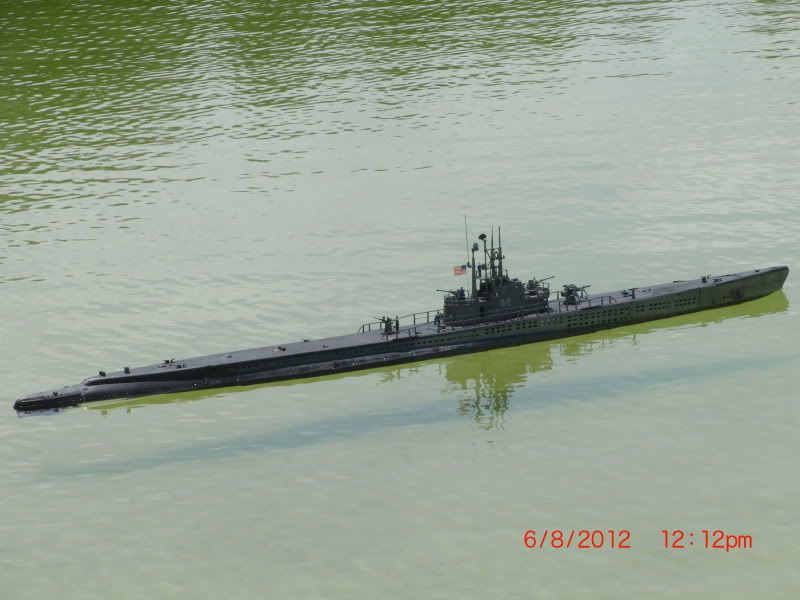
    Model Description: 1:48 scale WWII Gato class Submarine
    Sub-Driver: Meriman/Caswell 3.5 Mod. 2 = (Twin Drive motor)
    Basic ( Gas ) Ballast System

    Motors: Twin- Traxxas- Titan Marine-550 air-cooled 14.4V
    ESC: Mitronics- Viper Marine-40
    Receiver: Sombra Labs 8 - 8 channel RX ( no longer available)
    Pitch Controll: Mike's Sub Work's - UPC-1 controller
    Servos: Caswell- BT100 (Standard servos)
    Battery: Venom- 5000Mah Lipo
    UBEC: RCTimer- Output 5V- 3A continuous
    Failsafe: Mitronics- Micro failsafe
    Transmitter: Polk's- Tracker- lll (8) channel transmitter- This radio is no longer available


    Attached Files
    Last edited by Anuci; 01-31-2014, 08:08 PM.
  • He Who Shall Not Be Named
    Moderator
    • Aug 2008
    • 12255

    #2
    Andy has long advocated the stand-alone, high current BEC. I, only recently, came to appreciate the utility of the device -- it solving many of my randum 'glitching' problems. A device we now advocate being used within all 2.5 and 3.5 SD's (and our soon to be released 3" SD).

    David
    Who is John Galt?

    Comment

    • greenman407
      Admiral
      • Feb 2009
      • 7530

      #3
      Welcome back Al! Good to hear from you. You owe me a phone call.
      IT TAKES GREAT INTELLIGENCE TO FAKE SUCH STUPIDITY!

      Comment

      • Subculture
        Admiral
        • Feb 2009
        • 2119

        #4
        Originally posted by He Who Shall Not Be Named
        Andy has long advocated the stand-alone, high current BEC.
        It would be helpful if some manufacturers of ESC's were a little more forthcoming about the current capacity of the built in regulators used for the BEC's. Some will give out an arbitary figure like 5 volt 1A BEC. But 1A at what main voltage? The regulator might supply 1A of current from say a 6 or 7 volt system, but what if you hook it upto 12 volts. Then the regulator is working much harder.

        Unfortunately I see a lot of devices used which are barely capable of supplying a single servo, let along two or three. Some ESC's are equipped with pretty good regulators. The Mtroniks 'sub' range of ESC's have a decent linear regulator mounted externally to the main case. This should be enough to supply a reliable feed for about three normal analogue servos, provided you don't go too high on the voltage (no more than 12 volts and preferably lower).

        Switchmode BEC's are capable of supply large amounts of current fairly efficiently. They are electronically 'dirtier' than linear BEC's, but I know of a few people using them with no problems to report.

        Comment

        • Anuci
          Banned
          • Aug 2008
          • 165

          #5
          Thank you again for your input, Subculture. Although I've read some of your comments and input on a variety of subject matter, I don't believe I've actually seen any postings relating to the models you may presently own or have owned in the past. Then again, I may have simply missed that information. I'm sure we would all enjoy learning of some of your past projects, or at least one by which you may have regarded as your favorite R/C model submarine. The rc equipment you had personally found most functionable and reliable enough to have installed within your own submarine would certainly be interesting reading, and obviously useful to many of us in the hobby, for certain.

          Regards,
          Al

          Comment

          • Slats
            Vice Admiral
            • Aug 2008
            • 1776

            #6
            Originally posted by Subculture
            It would be helpful if some manufacturers of ESC's were a little more forthcoming about the current capacity of the built in regulators used for the BEC's. Some will give out an arbitary figure like 5 volt 1A BEC. But 1A at what main voltage? The regulator might supply 1A of current from say a 6 or 7 volt system, but what if you hook it upto 12 volts. Then the regulator is working much harder.

            Unfortunately I see a lot of devices used which are barely capable of supplying a single servo, let along two or three. Some ESC's are equipped with pretty good regulators. The Mtroniks 'sub' range of ESC's have a decent linear regulator mounted externally to the main case. This should be enough to supply a reliable feed for about three normal analogue servos, provided you don't go too high on the voltage (no more than 12 volts and preferably lower).

            Switchmode BEC's are capable of supply large amounts of current fairly efficiently. They are electronically 'dirtier' than linear BEC's, but I know of a few people using them with no problems to report.
            The BEC issue is something that I have been banging on about for years.
            Since I have been running Switchmode BECs I have had zero glitches on the water.
            I totally agree with Andy on this - whom has been instrumental in providing generous and always on the mark information.

            A rule of thumb I use for those wanting to know the limits of the on-board or linear type BECs of ESCs is that whatever the manufacturer states the amperage to be - accept that amperage is only ever available at the lowest input voltage and more to the point, accept that the figure stated is a peak rather than continuous amperage available. If the ESC with the BEC has an input voltage of 6 to 12 volts, and you running 12 volts - halve the available amperage. That is set up a linear equation - starting from the lower input voltage and incrementally and proportionately reduce the the stated amp peak on the ESC for every additional volt you are inputting above the minimum input voltage. But with the widespread low cost switchmode BECs now available far better rule of thumb is to simply buy a 3amp or higher unit and neutralise the on board BEC of the ESC but removing the red wire going between the ESC and the RX.

            The only thing I'd disagree with is my experience of using the Mtroniks ESC's BEC is I have had a string of BEC failures. And this was running 7.2v input. It might be the fact I prefer fullsize servos, but even with just three in operation + the small servo for the SD vent / blow operation I have had more glitches than any other ESC. Neutralising the BEC from the ESC and running the switchmode type separate unit has been the key to rectification and success. Mtroniks make a fine ESC. I use them, but its SOP for me to fit the separate BEC.


            J
            Last edited by Slats; 12-20-2012, 08:42 PM.
            John Slater

            Sydney Australia

            You would not steal a wallet so don't steal people's livelihood.
            Think of that before your buy "cheap" pirated goods or download others work protected by copyright. Theft is theft.


            sigpic

            Comment

            • He Who Shall Not Be Named
              Moderator
              • Aug 2008
              • 12255

              #7
              An excellent observation as to the receiver bus needs of our submarines, John. Clearly the stock ESC's (specifically, they're BEC circuit) are not up to the task of supplying device current load at the 5-volt needed off the receiver bus. Other than 'robots' I can't think of any other r/c vehicle out there that presents a higher current draw off the bus than r/c submarines. It has been through Andy's and your prodding that finally convinced Mike and me to secure, offer, and promote use of a dedicated BEC within our SD's. Thanks, guys.

              David
              Who is John Galt?

              Comment

              • Slats
                Vice Admiral
                • Aug 2008
                • 1776

                #8
                Originally posted by He Who Shall Not Be Named
                An excellent observation as to the receiver bus needs of our submarines, John. Clearly the stock ESC's (specifically, they're BEC circuit) are not up to the task of supplying device current load at the 5-volt needed off the receiver bus. Other than 'robots' I can't think of any other r/c vehicle out there that presents a higher current draw off the bus than r/c submarines. It has been through Andy's and your prodding that finally convinced Mike and me to secure, offer, and promote use of a dedicated BEC within our SD's. Thanks, guys.

                David
                Great - so we can buy these from Caswell? Any specs on these please?

                These are the one's I use:
                Hobbyking - the world's No1 Online Hobby Store. We stock a huge selection of RC products from Planes right through to Drones and all accessories. Visit Us Today.


                J
                Last edited by Slats; 12-20-2012, 11:11 PM.
                John Slater

                Sydney Australia

                You would not steal a wallet so don't steal people's livelihood.
                Think of that before your buy "cheap" pirated goods or download others work protected by copyright. Theft is theft.


                sigpic

                Comment

                • Kazzer
                  *********
                  • Aug 2008
                  • 2848

                  #9
                  Originally posted by Slats
                  Great - so we can buy these from Caswell? Any specs on these please?

                  J
                  Stop messing about - just get a Sub-driver!

                  Comment

                  • Anuci
                    Banned
                    • Aug 2008
                    • 165

                    #10
                    Hello all,

                    I'm revising an earlier posting here regarding my latest addition of electronics to my Gato boat.
                    Well it has been a while since I've installed the stand alone BEC ( battery eliminator circuit ) to the mix of other electronics within the motor compartment. This is the unit used here: http://www.activepowersports.com/cas...ing-regulator/
                    While initial testing of the various on board equipment after the instalation of the BEC appeared to all perform satisfactorily, later testing resulted in glitching of other various devices with either negative or pulsating power surging of the motors, this both while running in forward and reverse, At first, I thought this issue was the result of low battery voltage as it appeared to temporarly correct itself later when a fresh battery pack was used. However, when at long last I had found some time to take the sub to the pond, and while making preparations to do just that I discovered this problem resurfaced, showing its ugly face once more. Oh brother!, needless to say the mission was cancelled. Long story short, I disconnected the bec and found all ran well once again. Yea, I don't have a clue. Having said that, I do remember there being a difference between the various bec devices, eg switching vs. linear. Along those lines, I'm not quite sure if there is in fact any direct relationship with the type of bec used and the issues which developed after installing the Castle Creation BEC mentioned here. As an alternative, and when in doubt, I generally try something else. In this case I've ordered a battery eliminator circuit as advertised here on the Caswell forum and will give it a shot. I'm of the understanding it is of the linear type and I'm hoping to get around this issue with this particular type of BEC. Stay tuned!
                    In the mean time I've removed the previously posted info. regarding the Castle Creation 10A switching regulator, simply to play it safe, as this particular device may not, and I repeat may not be best suited in with the mix of other various electronic components crammed into the confines of your subs motor compartment, this due possibly to excessive noise output within the unit itself.
                    Last edited by Anuci; 02-13-2013, 11:59 PM.

                    Comment

                    • Anuci
                      Banned
                      • Aug 2008
                      • 165

                      #11
                      Subculture has graciously provided an explaination between the two types of battery eliminator circuits ( BEC's ) in these following comments, and further pointed out that the BEC presently stocked by Caswell is of the switchmode style of voltage regulator. Thanks for this easy to read explaination, Andy.

                      A switched mode supply basically works by switching an inductor coil in
                      and out very quickly (usually about 400 times a second). They can be
                      configured to drop or increase voltage, called buck and boost respectively.

                      A magnetic field is induced in the inductor when it is doing this, and
                      it is that which makes them electrically 'dirty'.

                      Best quality units will have a grounded metal shield around them, steel
                      being best, but aluminium works and is lighter. That deals with the
                      inductor on the unit. Also a ferrite is usually wound around the output
                      lead to nix any nasty frequencies induced into the wiring by the conversion.

                      A simple analogy would be to imagine you're watering the lawn with a
                      hosepipe. The water pressure is too high, and you can't adjust with the
                      tap, so what could you do? Well you could add a bypass, and shunt a bit
                      of the water off down the drain, that's your linear BEC. Or you could
                      get some one to squeeze the hose on and off with their foot, that's the
                      switched mode. The latter mode doesn't waste any water, although energy
                      is expended by the person doing the squeezing- hence switched mode
                      supplies are never 100% efficient.

                      Linear converters don't create any dirty fields, but they generate a lot
                      of heat when the voltage differential is high and the current demands
                      are great.

                      For example. Lets say we have a model submarine operating off 12 volts,
                      and we want our usual 5 volt feed to the radio kit. Let's also assume
                      the current required is 1A, which is adequate for two or three servos if
                      they're not stalling, or thirsty models.

                      To see how much power is wasted in heat, we subtract 5 volts from 12
                      volts, which is 7 volts, and multiply that with the current, which gives
                      us 7 watts of power wasted in heat. That's 140% greater than the power
                      being delivered. Can you say inefficient? Plus you'll need a sizeable
                      heatsink to get rid of the heat if the regulator is to survive.

                      If the model was operating on a lower voltage, say 7.2 volts, then
                      things become much more benign. 7.2-5= 2.2, times that by the current
                      equals 2.2watts, under a third of the power wasted. Hence why linear
                      regulators work best in low voltage boats.

                      An equivalent switch mode supply will only use about half a watt.
                      Last edited by Anuci; 02-02-2013, 10:48 PM.

                      Comment

                      • Anuci
                        Banned
                        • Aug 2008
                        • 165

                        #12
                        In a follow-up to my earlier posting, this regarding my decision to install a stand alone BEC.
                        Let me begin by saying all is fine and running well for the most part at this point. This as result of changing out one bec for another which Caswell was stocking. However, as I'm sure the instalation of a stand alone BEC will ultimately be for the better, I'm not exactly sure of a couple things which I found as result of this instalation.
                        First off, although all of the electronics appear stable and glitch free, I am now finding some variation in motor speed at pre-set speeds. The RPM of the motors appear to increase and decrease slightly when running at these pre-set speeds in a pulsating manner, as this was not realized when previously using the bec which was built into the speed controller.
                        Second, upon initial power-up of the motors there is a slight hesitation both in forward and reverse , and the speed of the motors are less controlable at low end, accelerating quickly at the slightest throttle-up. I may look to re-program the speed controller to determine if there is any substantial change to any of these conditions.
                        Let me first point out that my decision to use a stand alone BEC rather than the bec unit incorporated within my ESC was more of a precautionary measure, and not because of any direct or indirect issue I had been experiencing with any of the electronics within the motor compartment, this and as a direct result of the number of on board devices drawing power off the low amperage output of the BEC built into the speed controller I had been using .
                        To finalize, at this point I fully intend to continue with the set-up as is, looking to further evaluate the operation of the boat when out on the pond. If I feel the need, I may decide to simply return to the previous set-up, using the ESC's battery eliminator circuit.
                        The BEC unit was by far one of the least expensive devices purchased thus far, so, no harm no foul were my thoughts.

                        Until next time,
                        Keep a steady bubble!
                        Last edited by Anuci; 02-14-2013, 02:03 AM.

                        Comment

                        • Anuci
                          Banned
                          • Aug 2008
                          • 165

                          #13
                          I'm beginning to think I should start off these posts with " Once upon a time", but I simply thought I'd pass this info on as a pretext to how electrical connections and the water they are subjected to can be at the route of much of the evil we experience from time to time in this particular hobby.
                          I had recently found that while all the accessories intalled within the motor compartment of my sub-driver were working fine, the motors themselves would not respond to command of the TX. While I continued to throtle up power on my transmitter I further discovered the servo's would begin to glitch. While in the process of diagnosis, I not only made a preliminary visual inspection of the boats wiring, but also conducted a test with my voltmeter to determine if electricity was making its way to the various electrical bus terminals as well as the electronics within the motor compartment. I found that upon using another externally connected battery, and one which was connected directly to the motor bulkhead power bus, this revealed positive results, and all worked fine.
                          I was prompted to then pull the 11.1V lipo battery from within the battery compartment of the boat, and conduct a direct connection of that battery to the motor bulkhead power bus, as I did earlier with a 7.2V Nimh battery pack. I was happy to see everything then working as it should.

                          With this new info. and eliminating suspected possible issues with the battery or maybe even the ESC as the source of the problem, I then went on to re-examine all the remaining electrical wiring connectors within the boat much more closely, rather than depending entirely upon the readings from my voltmeter to determine how much power was being provided to the various bus terminals. This closer inspection revealed two of the battery connectors while visibly appearing OK, internally they were most likely compromised by broken wire strands, obviously not permitting the full power from the battery to pass on as it should.

                          What I learned from this examination process was that although the voltmeter had indicated sufficient voltage passing through the wiring from point (A) to point (B),
                          ultimately there was insufficient voltage to power the motors while under load. As result, I then replaced the connectors on the battery compartment bus. and proceeded to conduct further testing of the main power to the motor compartment and various electronics which only then revealed positive results.

                          Hopefully this info. will be of use to someone with a similiar concern, and help with diagnosing such issues. If I have learned anything in these diagnostics steps is that you be well served to look at the simple cause rather than jumping to conclussions. Replacing or addressing items which are least costly first, and then moving on to the next possible culprit in the series of offenders should help keep repair costs down.

                          Until next time, "Keep a steady bubble".
                          Al,
                          Last edited by Anuci; 03-05-2013, 11:45 PM.

                          Comment

                          • Subculture
                            Admiral
                            • Feb 2009
                            • 2119

                            #14
                            I've never experienced many problems with cabling over the years- perhaps I've been lucky. Do you pull the wires about a bit?

                            Comment

                            • Anuci
                              Banned
                              • Aug 2008
                              • 165

                              #15
                              Hello Andy,
                              That's a good question, and I'm glad to hear you haven't experienced any such issues with your set-up, and maybe this incident is isolated to me.
                              First let me say because of the arragement of the various cylinders within the hull of this particular boat of mine, it may be a bit unique, in that there are three (3) separate wtc's within the hull. There is a cylinder which is used to house the Bowplane Retract Mechanism, another for the Main Battery Compartment, and then there is the actual Sub-Driver (WTC) itself. The wiring is externally located and interconnected between these various components for purpose of utility. Each unit at times may require servicing and removal from within the hull eg. to access the battery, etc, thus the elecrical wiring and connectors are removed from there respective electrical bus. to permit such removal. Over time water corrosion, and general wear encountered in the removal and re-attachment of these particular wiring connectors, they will then become brittle and the inner wire strands subjected to fraying.
                              The end result is what has been described in my previous post. I'm sure there may be another way of skinning this cat, such as maintaining the connection to the external power bus. and using a different type of intermediary connector such as a deans or the like to connect and disconnect, and I may look to do just that in the future, as this may prove to limit the wear and tear to the actual connectors POS/NEG mounting to the outer face of the cylinders end cap.

                              Hope I'm being clear with this explanation.

                              Regards,
                              Al
                              Last edited by Anuci; 03-06-2013, 02:10 PM.

                              Comment

                              Working...