-
If you end up doing a late-model Permit class version, here's a render from my extensive CAD library of US boats:
-
I'm doing a more detailed analysis of the photo's of the PUFFS arrays, with better correction of perspective effects. I'll report back with an update in a couple of days.Leave a comment:
-
-
Thanks for the information on the sonar array configurations. Indeed I had assumed that the PUFFS end plates would have only been used on some Permit class submarines in the early-mid 1960's, with only the photo's of Thresher and Barb confirming that they were fitted to those boats.
I found a photo of the later deployable towed array installation on Plunger taken in the late 1980's, which nicely shows the support structure and modification of the rear plane;
https://www.reddit.com/r/submarines/...dock_note_the/
Would it be correct to assume that for the earlier generation of towed arrays (attached and removed at sea), were connected to a baseplate on the end of the starboard plane similar to that on photo's I've seen of the Skipjack & some SSBN's?
Incidently, I have started constructing a CAD model of the Thresher / Permit using Greg Sharpe's plan as the starting point & progressively integrating data from other drawings and photo's. For the Thresher/Barb PUFFS end plates I made a preliminary estimate of the dimensions from photo's and incorporated this into a layer in the model as follows;
- Length 9.82'
- Height 8.6'
- Maximum thickness: approx 1.6' to 1.73' giving a chord/thickness ratio of 16% to 17.5%
-Plate Position: End 2.32' forward of rear tip edge of dive plan
- Section: Used a NACA0016.5 section, but need to check again whether the max thickness might be further back along the chord.
If anybody has an actual dimensions this would be useful for confirming these values. I believe USS SS-581 Blueback has a similar arrangement fitted to the rear planes.
Also, the plan and construction photo's give a diameter for the rudder/plane bearing blocks of around 22" which confirms that these can be enclosed within the control surface.
Attached is a screenshot screen shots of the model so far, very much a work in progress. The basic hull shape is fairly easy to model, being axisymmetric (I got quite a good fit to the shape using a Myring hull equation) & the basic hull shape is also shared with the Sturgeon class. Of course adding the details takes a bit more time...
Attached FilesLeave a comment:
-
-
It really comes down to which generation of fast boat you want to build. A lot of experimentation occurred in the 60's with older sonars adapted to the new hull forms, so accurate class info is difficult to come by,
The long baseline array for the PUFFS and it's progeny were made redundant by the towed arrays that were back-fitted in the 70's when the Q-5 was retrofitted to the older SSNs and standardized on the 688s. Whereas PUFFS measured the arc of the sound wave as it was detected by each phone in the array to determine range, this calculation was made more accurate by using a similar algorithm to measure the arrival time to to determine the arc via the sphere and the towed array, yielding much greater accuracy. The Q-6 installed on Tridents incorporated a Line array in the ballast tanks angled in such a way to maximize bottom bounce returns and a wide aperture, due to the length made for a good array, though not as sensitive as the towed array (TB-16 / TB-23 / TB-29.)
As a 21-year sonar tech for both the Navy and DoD, I only encountered PUFFS twice - on the Tang class and Dolphin, where it was more of a curiosity than a necessity. It was long gone on the Permit and Skipjacks in the 70's.Leave a comment:
-
Thresher / Permit control surface bearing blocks & Hydrophone end plates
I've started researching a bit the different configurations of the Thresher / Permit class & have a couple of questions on the rudder and rear dive plane arrangements.
Most plans & scale models of the Thresher / Permit class submarines show the rudders and rear planes rotate around a fixed bearing block with a cutout in the control surface. However, launching / construction photos of the Thresher, Plunger as well as one Barb in drydock appear to have the rotation fully enclosed in the control surface. Therefore, is it possible that the bearing block was a later modification or incorporated only specific boats? Unfortunately, I've only found a few photo's of the rear control surfaces.
Here are links to the specific photos ;
SSN-593 Thresher launch photo, showing upper Rudder
SSN-594 Permit Stern section showing dive plane and rudder axes
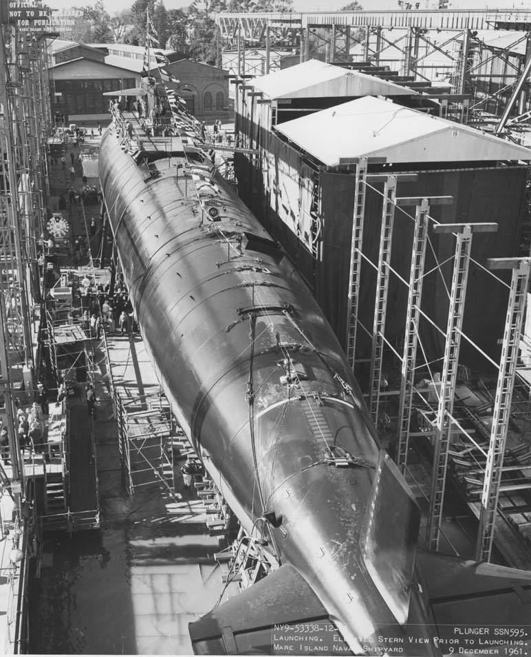
SSN-595 Plunger construction photos, showing upper Rudder and Rear Dive Planes
SSN-596 Barb Drydock photo showing Rudder
Interestingly the photo of Barb shows the installation of an element of the BQG-2 Hydrophone array in an end plate on the rear dive planes. A similar arrangement appears to have been fitted to the Thresher at the time of her loss as it is visible in a couple of photo's taken by the Trieste during survey of the wreck in 1963-1964;
Does anyone know if hydrophone endplates were also fitted to other boats in the class?


Leave a comment: