upgrading the SSY 1/96 ALFA kit

Collapse
X
 
  • Time
  • Show
Clear All
new posts
  • He Who Shall Not Be Named
    Moderator
    • Aug 2008
    • 12255

    #76

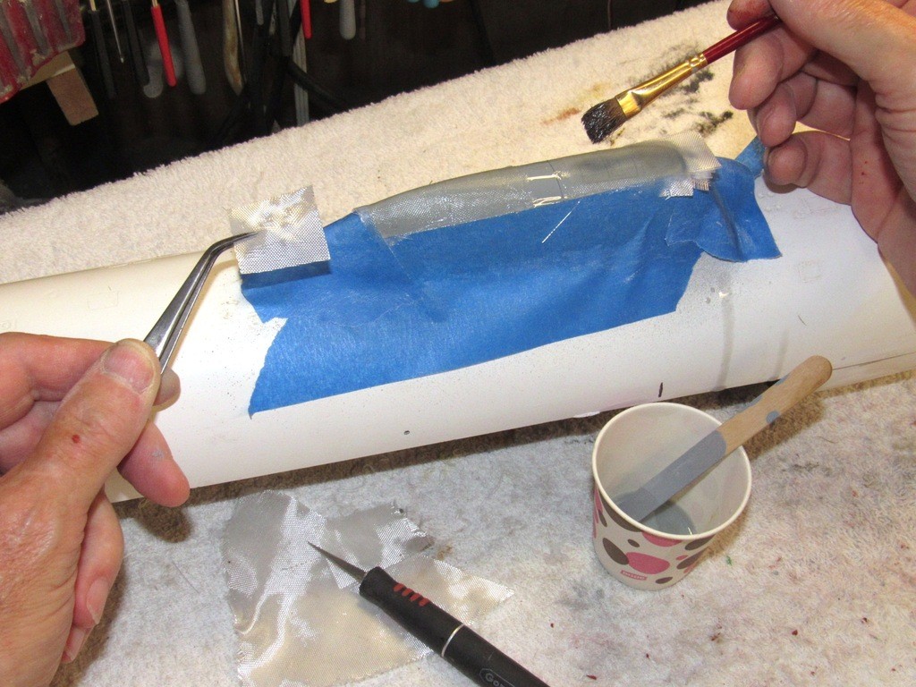
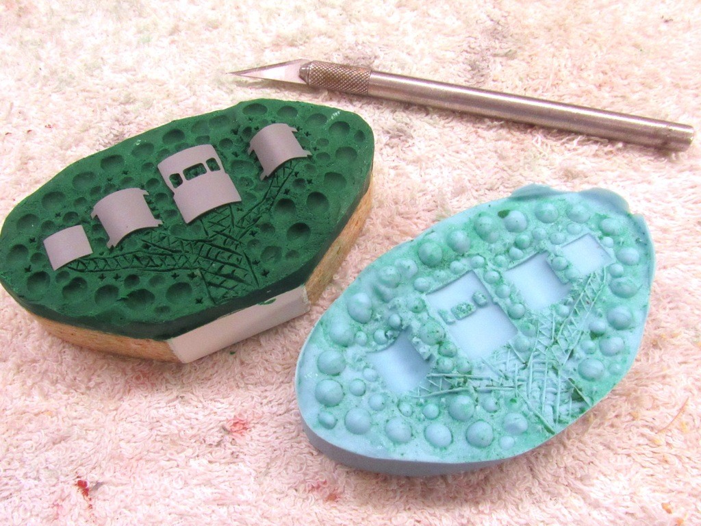
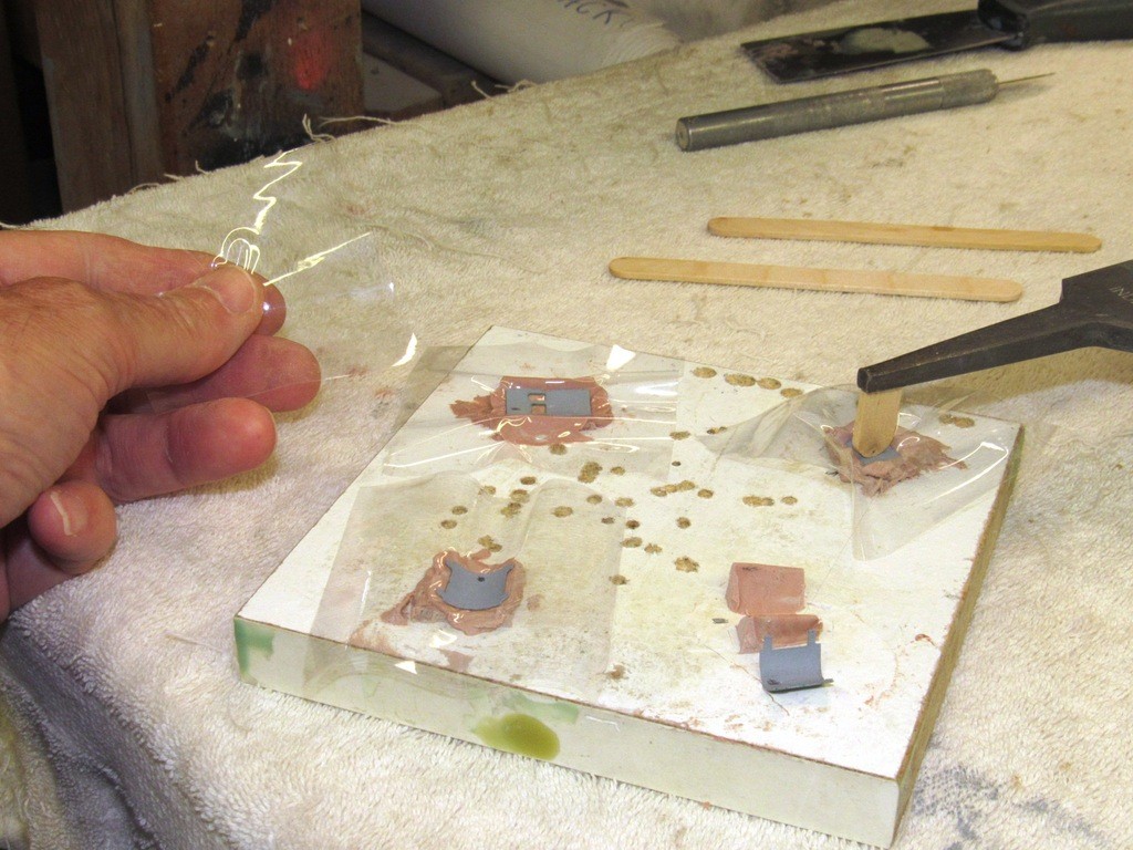
    The never-fail West System epoxy laminating resin was mixed up, and I laminated four layers of one-ounce glass cloth over the three mast hatches and bridge enclosures.

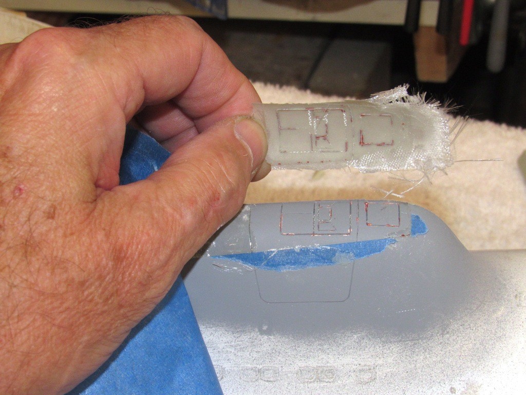
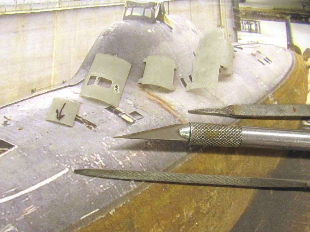
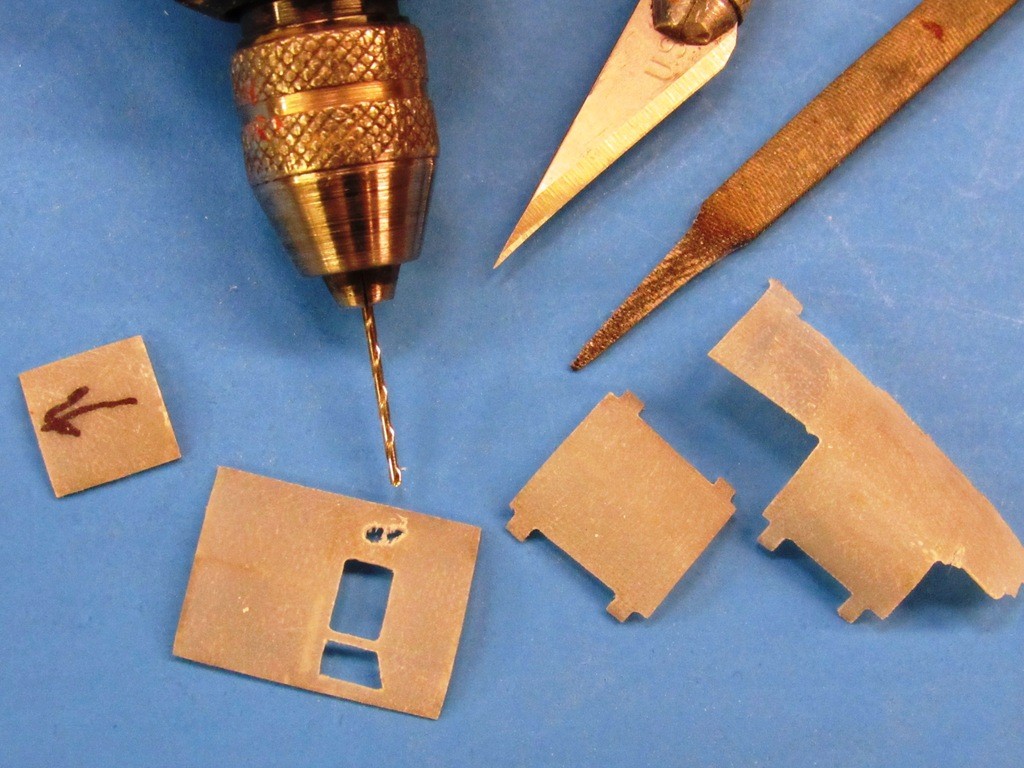
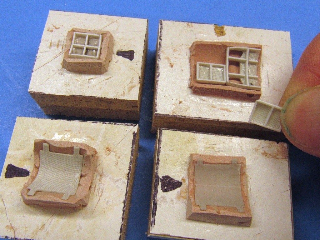
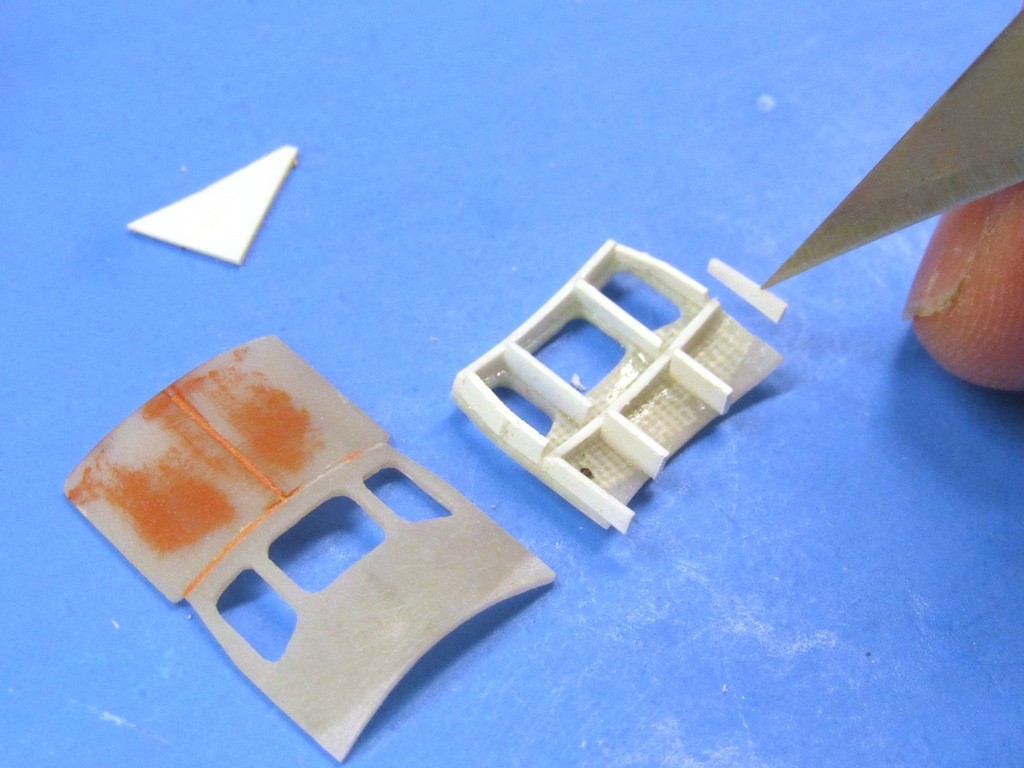
    I did manage to damage some of the engraved work when I pulled the cured GRP blanks off the sail. But, it was all quickly fixed with putty and the finishing scribe, followed by a careful wet sanding. You can see here how the engraved lines of the sail, now relatively high-relief positive lines on the underside of the blank, capture perfectly the outlines of the hatches. I followed those lines as I cut each hatch intermediate master to shape.

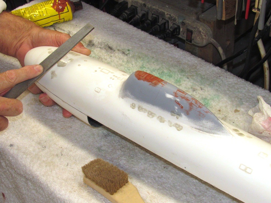
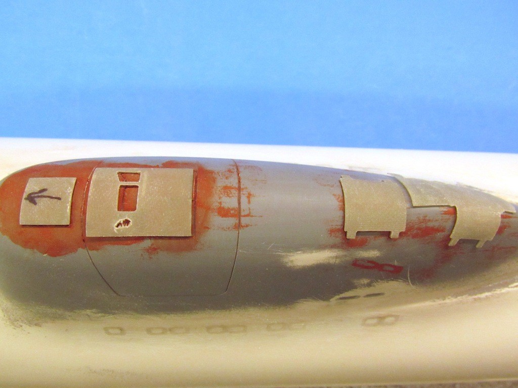
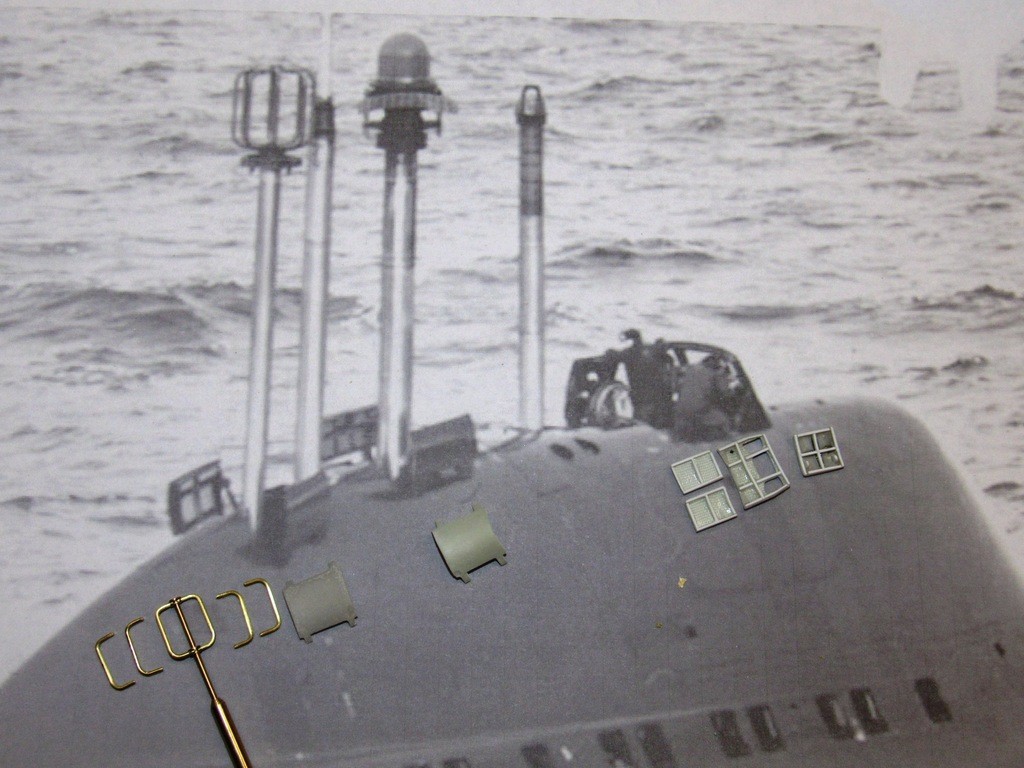
    After the lay-up atop the sail, and before the epoxy mix changed state, I thickened it with some talc, scrubbed the entire upper hull with a lacquer thinner drenched 3M abrasive pad, and dabbed the goo over all of the model hulls original engravings (except the torpedo tube shutter doors). After the epoxy had cured hard I filed and sanded the work down flush with the surface of the hull. From this point I could re-scribe the hull with a more accurate representation of access hatches, doors, salvage fittings, and the like.


    Who is John Galt?

    Comment

    • trout
      Admiral
      • Jul 2011
      • 3545

      #77
      I am really enjoying the information you have been sharing. I appreciate that you have always shared your information and knowledge. It takes time to document ones work and to publish it in such a way as to give enough information to educate a student wanting to follow. Thank you!
      If you can cut, drill, saw, hit things and swear a lot, you're well on the way to building a working model sub.

      Comment

      • He Who Shall Not Be Named
        Moderator
        • Aug 2008
        • 12255

        #78
        Originally posted by trout
        I am really enjoying the information you have been sharing. I appreciate that you have always shared your information and knowledge. It takes time to document ones work and to publish it in such a way as to give enough information to educate a student wanting to follow. Thank you!
        Thank you, Tom. Means something coming from an accomplished Craftsman such as yourself. Just passing the torch (unfortunately, there are so few outstretched hands to take it these days -- I fear you and I are among the last of the breed ……….... the robots win...... …… let us hope the electricity and those who write code never fail us).

        David
        Who is John Galt?

        Comment

        • Scott T
          Commander
          • May 2009
          • 378

          #79
          ? Why not build a form around sail and make rtv mold. Then pour a rtv part in that mold and remove rtv material around doors at scribed lines to create a master for doors? Like cutting a linoleum printing block. Like cutting air channels in your molds.
          Last edited by Scott T; 08-26-2019, 12:24 AM.

          Comment

          • He Who Shall Not Be Named
            Moderator
            • Aug 2008
            • 12255

            #80
            Originally posted by Scott T
            ? Why not build a form around sail and make rtv mold. Then pour a rtv part in that mold and remove rtv material around doors at scribed lines to create a master for doors? Like cutting a linoleum printing block. Like cutting air channels in your molds.
            I'm not clear on this, Scott. Pull an RTV tool directly off the top of the sail, then cast an RTV item within the face of that tool? Can you please re-phrase so I can understand your scheme here?

            David
            Who is John Galt?

            Comment

            • Scott T
              Commander
              • May 2009
              • 378

              #81
              Yes make a cast like you are doing your face then pour a bust of the original.
              Then carve away everything that is not doors down a depth 1/16 or 1/8in.
              Then use that to make molds for your doors.
              Cutting the RTV seems easier than cutting the fiberglass.
              You could also do the door openings by digging them out of the RTV on a separate RTV cast.
              Hope it makes sense and works.


              Click image for larger version

Name:	carve.jpg
Views:	220
Size:	62.9 KB
ID:	133919
              Last edited by Scott T; 08-26-2019, 01:04 PM.

              Comment

              • He Who Shall Not Be Named
                Moderator
                • Aug 2008
                • 12255

                #82
                Originally posted by Scott T
                Yes make a cast like you are doing your face then pour a bust of the original.
                Then carve away everything that is not doors down a depth 1/16 or 1/8in.
                Then use that to make molds for your doors.
                Cutting the RTV seems easier than cutting the fiberglass.
                You could also do the door openings by digging them out of the RTV on a separate RTV cast.
                Hope it makes sense and works.


                Click image for larger version  Name:	carve.jpg Views:	1 Size:	62.9 KB ID:	133919
                I think I'm following you, Scott. By the way, I appreciate you taking the time and effort to illustrate with scrap drawing and photo -- very useful. However, once I present the hatch work from start to finish we can discuss wither or not my or your process is the superior methodology for the task. Regardless, you're presentation has given me considerable food for thought. I'm learning something new.

                It's been my experience that machining cured GRP is much easier than cutting, sawing, grinding, or abrading the ever elusive flexible RTV rubber.

                David
                Last edited by He Who Shall Not Be Named; 08-26-2019, 01:22 PM.
                Who is John Galt?

                Comment

                • He Who Shall Not Be Named
                  Moderator
                  • Aug 2008
                  • 12255

                  #83


                  After popping off the GRP sail hatch blank from atop the sail I inverted it and followed the raised hatch outlines to cut each hatch assembly away from the surrounding GRP material. This shot of that nearly completed task shows the intermediate master hatches laid over a good shot of a prototypes sail.

                  I’m well underway here with punching out the openings for the bridge windscreen deadlights.


                  What will become the hatch intermediate masters are test-fit atop the sail to insure I have their orientation correct as I carefully match their outlines to those of the engraved lines atop the sail.

                  Check twice cut once, as they say.

                  (I assume that the forward hatch fairs over the boats snorkel induction mast – the one with the arrow on it. I can’t find any documents stating its function. Is there anyone in the audience who can give me a definitive answer to that question??).


                  GRP, once cured hard, is a total ***** to cut and saw. The best tool for parting this material is a carbide cut-off wheel. For small, fiddly work like this I use the thinnest, unreinforced carbide wheel available, spun at high RPM’s. (Don’t forget the eye-protection as these things WILL shatter, spewing shrapnel everywhere when they explode in your face). Final shaping is done with diamond files and stiff sanding sticks.

                  I’ve found the best tool for roughing out holes in the center of GRP laminates is an old drill bit pressed into service as a poor man’s router bit. High speed, carefully applied lateral pressure, and luck produce a hole of approximate size and shape. The work is finished with knife, carefully selected and skillfully used jeweler’s files (sometimes modified as you see here), and purpose built stiff sanding sticks.


                  Once these intermediate hatch masters were cut to outline, they were given a final coat of primer and lightly abraded with #600 sandpaper used wet. They were then set into masking clay and the first half of a two-part rubber tool was poured. We’ve all seen that movie … moving on.


                  The initial plan was to use this intermediate tool to produce cast white-metal production master.

                  ‘Best laid plans of mice and men OFTEN go astray!’

                  Sure, these .025” deep cavities would present a lot of back-pressure to any filling medium, but I figured a tall sprue pipe – gravity producing a significant pressure-head that would force the liquid metal into these tight cavities – would get the job done. But, after many shots, ever increasing the height of the sprue pipe, and much foul language I could not get complete fills of the cavities. Round one to Murphy!

                  So, I switched gears and elected to cast GRP reinforced polyurethane and epoxy laminates in this tool. To insure a complete evacuation of all air within the cavities I employed the vacuum casting technique (yes, I’ve written about that, check past WIP’s). I got quick turn-around with the polyurethane resin glass reinforced pieces, but they (even with the encapsulated glass cloth) were soft and easily distorted by handling. Fortunately the epoxy units were found to have the properties I wanted: chemically stable, strong, and shape retention no matter how roughly I handled them.

                  Now, with several sets of suitable production masters in hand, I could proceed with one set to close open wills, and the other set to represent the hatches in the open position.


                  At my core I’m still a navy trained, ham-fisted, I-can’t-spell-it-but-I-can-lift-it Torpedoman. So, I did not trust myself to hand-hold this fiddly work. Here I’m producing conformal holding fixtures out of Bondo.

                  The process was easy: A catalyzed goop of Bondo was dumped on a scrap piece of shelving board; a piece of clear packaging wrap placed atop the goo to isolate the masters from the Bondo; and an intermediate master pushed into the muck and held down tightly (note the big file tang with a glued on popsicle stick ‘finger’ pushing a master down into the Bondo) as the filler changed state from stinky goo to solid.


                  And here are the holding fixtures in use. I’ve shaved away excess Bondo and have separated each holding fixture to make handling of the separate production master hatches an easier task.


                  To the left is the ‘closed’ production master for the three-piece bridge well closure; to the right I’m working the ‘opened’ windshield portion of the bridge well. These will join the other hatch production masters when it comes time to fabricate the disc-shaped spin-casting production tool used to make the small, detailed, white-metal fittings that go with the 1/96 ALFA fittings kit.

                  Though this shot gives some appreciation at how small the work is here, it’s not completely accurate. In practice I secure the hatch half atop the sickly side of a piece of double-stick tape (in some circles, sold as ‘servo tape’). That double-sided sticky tape secured to a piece of scrap shelf-board much like I did with the above holding fixtures. I handle the piece of shelving board in my massive rat-like paws rather than the tiny work itself. I’m old and shaky. Sue me!

                  Yes, the stringers and frames look to be much too big – and they are. These .020” thick pieces are best handled when over-size in height. Later, after all the pieces have been CA’ed within the production master they will be ground down with moto-tool sanding drum and cylindrical sanding ‘blocks’. Their heights reduced to a mean .020” which then gives them the appropriate ‘square’ section you see on prototype.


                  A sneak-peak at the eventual end-game to this madness: the creation of two sets of sail hatches. One set to cover the wells under an opening; and another set – each hatch split into two pieces – representing opened hatches. I’ve already done that work with the bridge windscreen and clamshell hatch halves, as well as outfitting these with .020” square stringers and ribs. The DF and radar-ECM well hatches are aft and are yet to be split and detailed with framing and actuator clevises.

                  I previously neglected to mention the extreme forward square hatch, which does not split like the others but swings up and is hinged on the starboard side – its practical function to fair over the well from which the snorkel (pending clarification) induction mast resides. At this point that hatch has been outfitted with framing as well as two clevises which make up to the hydraulic actuators that open and close the hatch.
                  Note that at the extreme left is a start of the DF antenna production master.


                  A quick look at the work done so far on the DF antenna: This particular one – seen on every ALFA I’ve found a picture of – has the atypical six part antenna rather than the simpler four part DF antennas seen on most other Soviet … err …. Russian submarines. The guys at the Malachite Design Bureau did this just to **** with me! How did they know?

                  Some minor-league machining involved with this unit. I’ll go into detail on that later.

                  God!! Will this job never end???????????


                  David


                  Who is John Galt?

                  Comment

                  • trout
                    Admiral
                    • Jul 2011
                    • 3545

                    #84
                    Please explain how you drilled those tiny holes on the brass rod or disk (the holes that will receive the antenna loops). This is amazing stuff you are sharing. I truly hope those reading this will understand the knowledge and experience being shared here by a master.
                    If you can cut, drill, saw, hit things and swear a lot, you're well on the way to building a working model sub.

                    Comment

                    • He Who Shall Not Be Named
                      Moderator
                      • Aug 2008
                      • 12255

                      #85
                      Originally posted by trout
                      Please explain how you drilled those tiny holes on the brass rod or disk (the holes that will receive the antenna loops). This is amazing stuff you are sharing. I truly hope those reading this will understand the knowledge and experience being shared here by a master.
                      Next installment (or the one after that) in this WIP epic will deal with lathe work and the use of a home-made indexing plate to establish hole spacing symmetry on a cylinder. (God I love big, important looking wourdes).

                      David
                      Handy but Math Dumb!
                      Who is John Galt?

                      Comment

                      • HardRock
                        Vice Admiral
                        • Mar 2013
                        • 1609

                        #86
                        A couple of photographs that might help.

                        Click image for larger version

Name:	6b1be95e6585732b.jpg
Views:	200
Size:	239.5 KB
ID:	133973

                        Click image for larger version

Name:	alfa3k.jpg
Views:	197
Size:	253.1 KB
ID:	133974

                        Comment

                        • He Who Shall Not Be Named
                          Moderator
                          • Aug 2008
                          • 12255

                          #87
                          Originally posted by HardRock
                          A couple of photographs that might help.

                          Click image for larger version

Name:	6b1be95e6585732b.jpg
Views:	200
Size:	239.5 KB
ID:	133973

                          Click image for larger version

Name:	alfa3k.jpg
Views:	197
Size:	253.1 KB
ID:	133974
                          OH, WOW!!!!! Never seen those before. Wonderful stuff, Scott. The scope head is no longer a mystery. Rock solid stuff!

                          And what appears to be the snorkel head-valve is indeed starting to look just like the design favored by the Malachite Design Bureau on their other boats. However, a mast -- its cylinder concentric with that of the (supposed) snorkel inductions -- projects up from the center of that valve. If it is indeed a snorkel induction mast, the centrally running mast (HF and/or VHF maybe) leaves little annular space for air to pass down to the diesel generator. I wonder if the lower picture isn't 'flopped', as all pictures I've seen to date show the single hatch for that well hinged on the starboard side -- your picture has it on the port side. But, great detail on the hatch actuator and bell-crank.

                          Great stuff there, Scott. Much appreciated, my friend.

                          David
                          Who is John Galt?

                          Comment

                          • HardRock
                            Vice Admiral
                            • Mar 2013
                            • 1609

                            #88
                            I think you are right. The top photograph is the right way around; I know that because the flag is not reversed. I'm sure that the bottom one is reversed now. I made three ot four different induction heads before I found this photograph and finally got a look at that real shape of the thing. Carry on. I love your work.

                            Comment

                            • He Who Shall Not Be Named
                              Moderator
                              • Aug 2008
                              • 12255

                              #89
                              Originally posted by HardRock
                              I think you are right. The top photograph is the right way around; I know that because the flag is not reversed. I'm sure that the bottom one is reversed now. I made three ot four different induction heads before I found this photograph and finally got a look at that real shape of the thing. Carry on. I love your work.
                              Yeah. Further evidenced of the flopped photo is the forward door and safety track are on the 'wrong' sides. Good stuff. And I love your work -- your magnificent NOVEMBER is in the queue, pal. We'll do that one right too.

                              That thing HAS to be a combined snorkel induction-antenna mast affair. And the first photo is so informative as to the scope head and ECM-radar antenna array. Good stuff, just in time as I'm turning brass today.

                              David
                              Who is John Galt?

                              Comment

                              • He Who Shall Not Be Named
                                Moderator
                                • Aug 2008
                                • 12255

                                #90
                                Confirmation! Thanks, Gantu.

                                David

                                Who is John Galt?

                                Comment

                                Working...