Welcome to our forums. For the best in R/C submarine kits, components and accessories, be sure to visit the Nautilus Drydocks
If this is your first visit, be sure to
check out the FAQ by clicking the
link above. You may have to register
before you can post: click the register link above to proceed. To start viewing messages,
select the forum that you want to visit from the selection below.
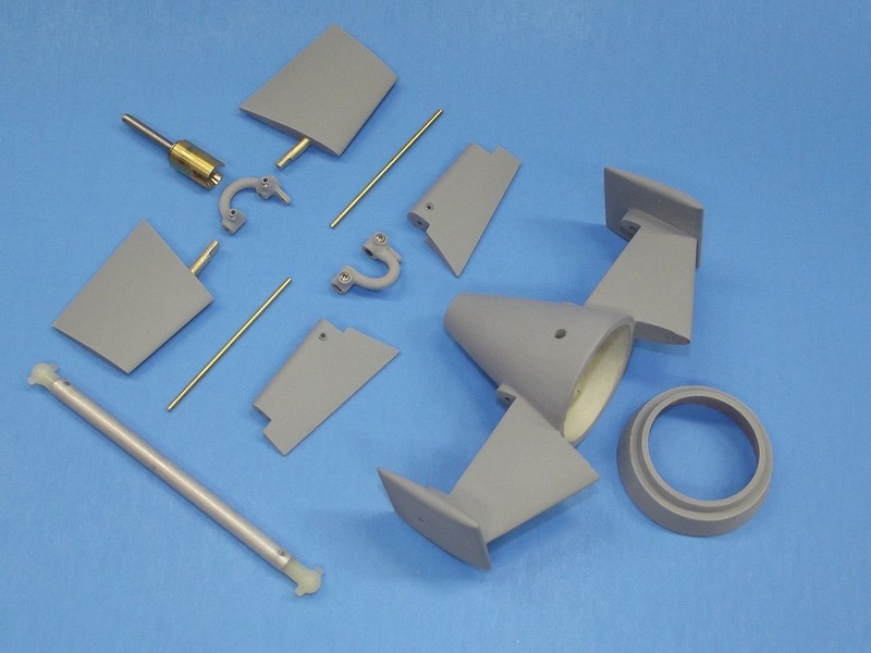
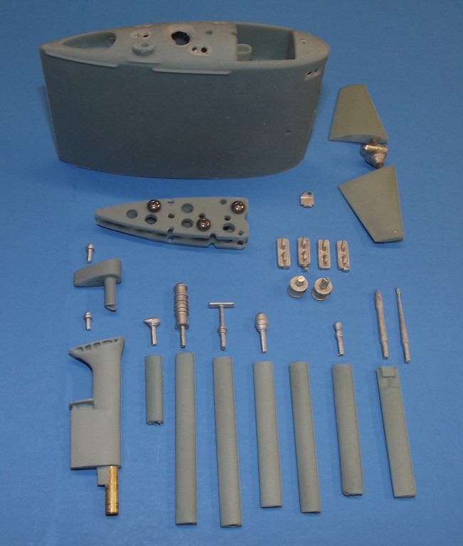
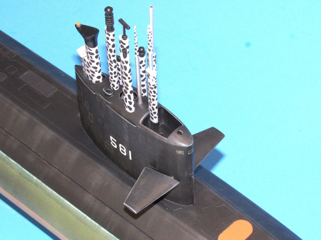
Remember, I'm an idiot with these things. But, the aft diving planes have a fixed brass rod imbedded in them. So, I was under the impression that the brass rod is inserted through the side plate and through the diving plane. I was trying to figure out how to put it together without breaking anything. It appears I'll have to cut off some of the brass rod to get it to fit......Attached is a photo
OK. This is not the way I engineered the stern planes. The problem is another contractor is producing the kit parts from Dave Manley's and my work.
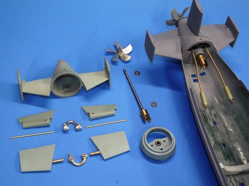
Grab the brass rod, rotate it to break the weak bond between it and the resin stern plane, and pull that sucker our. Widen the bore with a .096" bit and it will provide a non-interference fit with a proper .092" brass operating shaft. Are you following my WIP on this kit? In that you'll see the use of a bottom mounted set-screw to hold the operating shaft fast during assembly to the tail-cone.
OK. This is not the way I engineered the stern planes. The problem is another contractor is producing the kit parts from Dave Manley's and my work.
Grab the brass rod, rotate it to break the weak bond between it and the resin stern plane, and pull that sucker our. Widen the bore with a .096" bit and it will provide a non-interference fit with a proper .092" brass operating shaft. Are you following my WIP on this kit? In that you'll see the use of a bottom mounted set-screw to hold the operating shaft fast during assembly to the tail-cone.
David
OK, I erred on the bore you need for the stern plane operating shaft -- use a .063" bit, not the .096" bitt recommended above.
New questions:
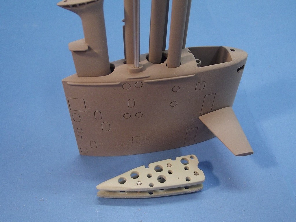
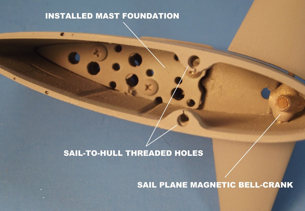
1. How is the support for the masts attached to the inside conning tower?
2. What size/vendor do you use for the shaft bearing?
Thank you
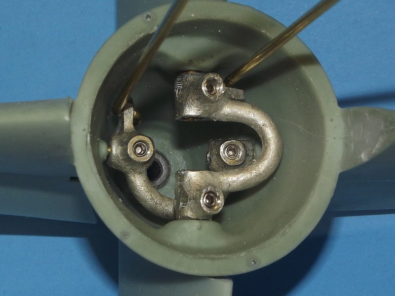
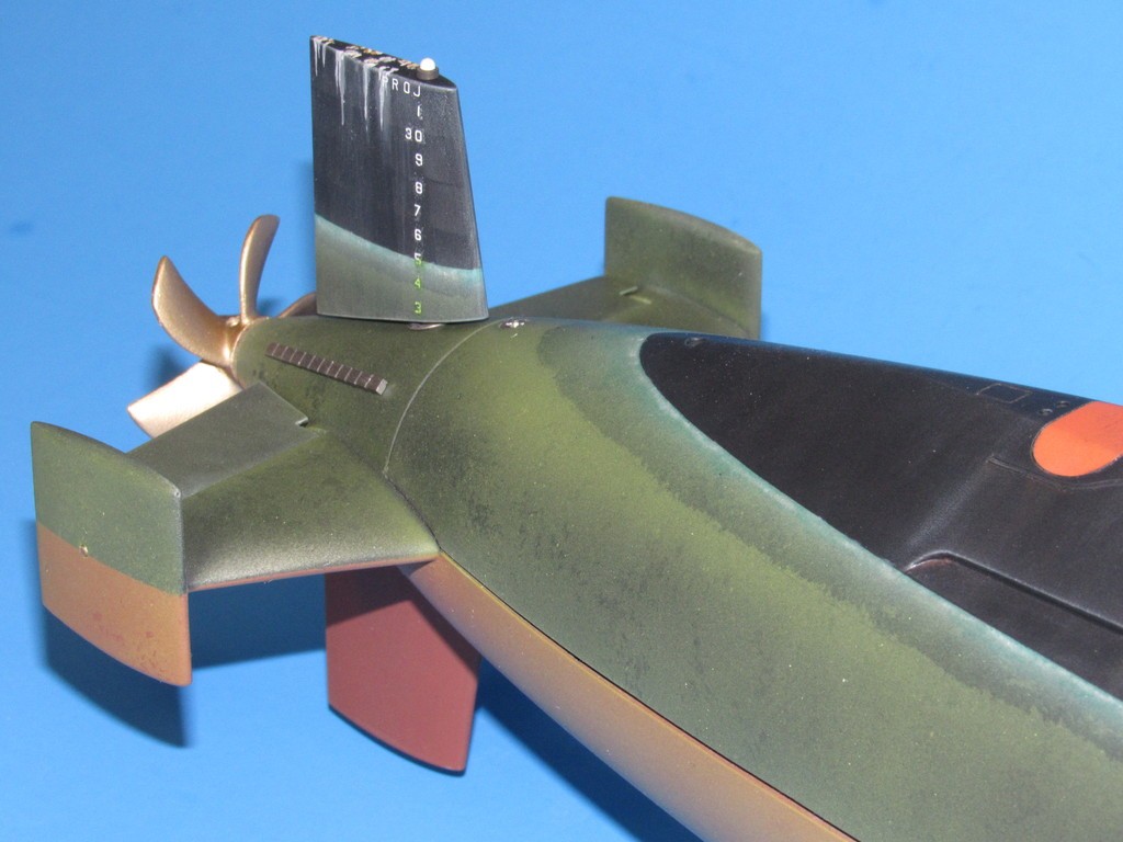
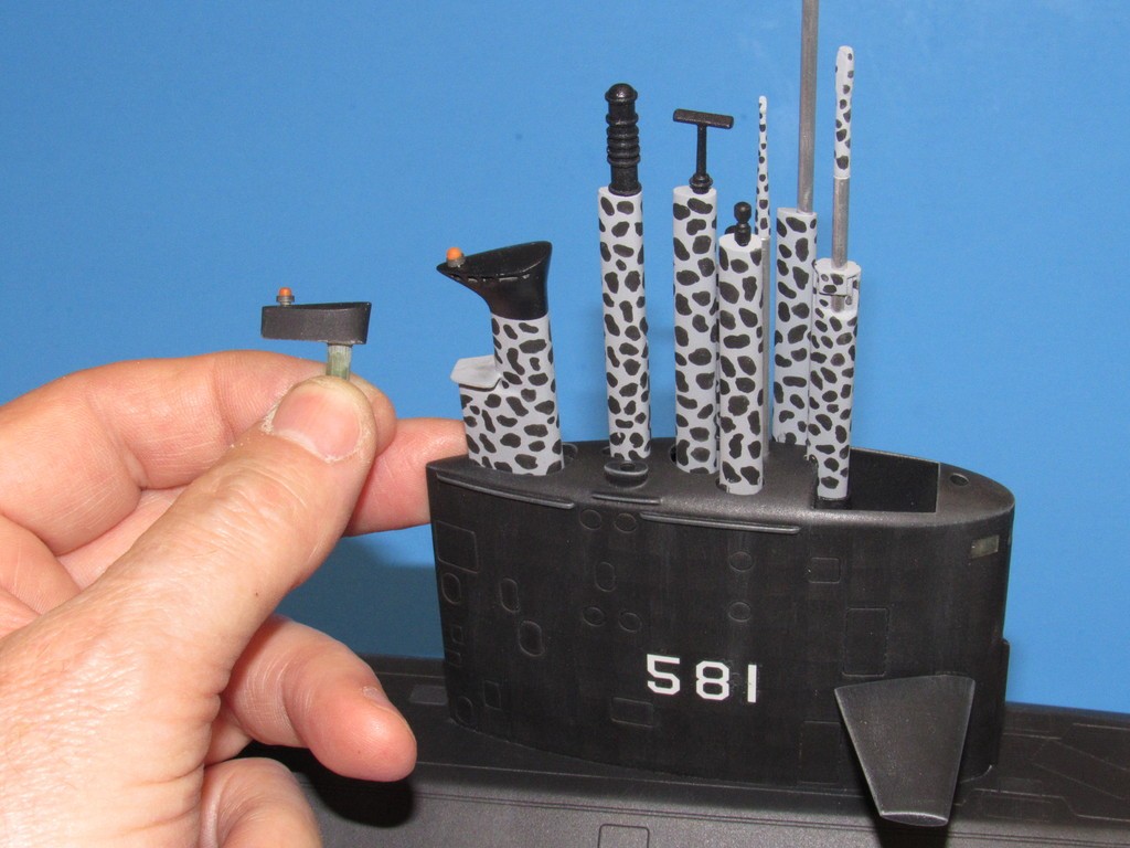
The mast foundation comprises two platforms that are bolted together -- this assembly is called (drum-roll, please!) the mast foundation. The foundation for the scopes and masts is attached permanently within the top of the sail with thin formula CA. BUT!!!!... only after repeated test trials and alterations to get all the masts and scopes to run parallel to one another and perpendicular to the top of the sail. The side-to-side orientation is in reference to the sides of the sail; the fore-aft orientation is in reference to the sails trailing edge.
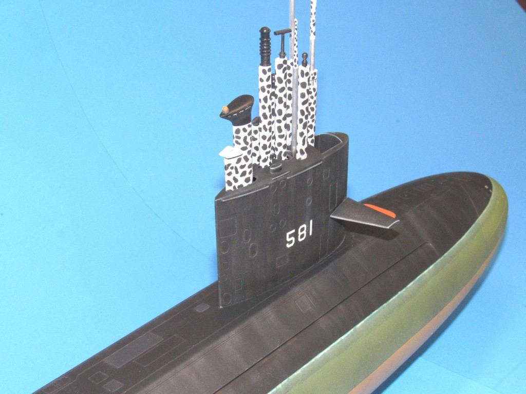
When done properly you wind up with this: an ability to remove the masts to suit your taste and what you would expect the real things to be doing while you blurt out chugging and alarm sounds as you fumble at the transmitter sticks.
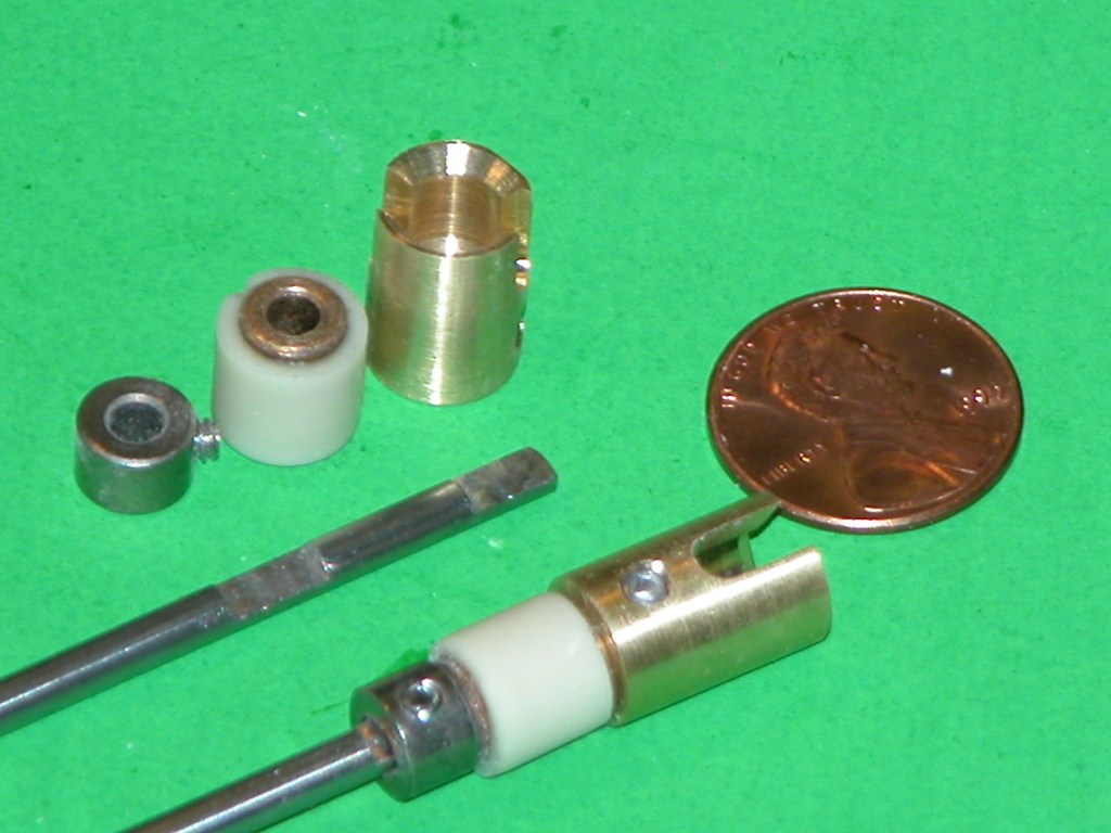
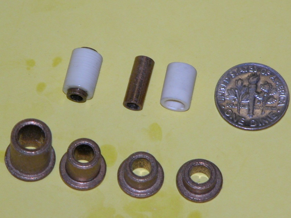
The shaft journal-thrust bearings are sized to run a 3/16" (.137") diameter shaft through a non-interference bore. They are flanged. Available from McMaster-Carr. Some examples
I noted on your WIP that the end of the upper hull is sanded/ground down to thin it out to match the tailcone. Wouldn't this weaken the area where the screw goes to attach the upper hull?


Comment