Revell Gato 1/72 - Newbie no more Part duex

Collapse
X
 
  • Time
  • Show
Clear All
new posts
  • trout
    Admiral
    • Jul 2011
    • 3545

    Revell Gato 1/72 - Newbie no more Part duex

    Part two of the build will be placed here. For the first part go to
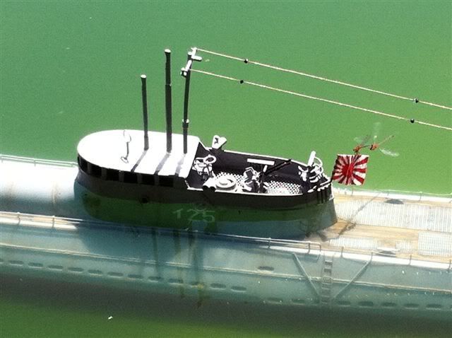
    https://forum.rc-sub.com/forum/build...vell-1-72-gato Waiting for some fun stuff to come in from Caswell inc. - Then I can document the electronics in the WTC. I will probably build up the deck/conning tower and misc. deck stuff while I wait. Having it painted - even quickly - makes it seem that much more exciting. This is really a beautiful submarine.
    Last edited by trout; 11-26-2018, 12:01 AM.
    If you can cut, drill, saw, hit things and swear a lot, you're well on the way to building a working model sub.
  • He Who Shall Not Be Named
    Moderator
    • Aug 2008
    • 12253

    #2
    I have over fifteen fully operational r/c submarines in my fleet and I regard the FOXTROT and the GATO as the most attractive of the bunch -- those two, at 1/72 scale are big enough to cut an imposing wake at the lake, but are suitable for most large swimming pools as well. And, boy, do they look neat cruising by at PD!

    I've had so much fun with the thing I have yet to give it a proper paint job and weathering.

    David

    Click image for larger version

Name:	030.jpg
Views:	1
Size:	83.8 KB
ID:	65874Click image for larger version

Name:	034.jpg
Views:	1
Size:	88.1 KB
ID:	65875Click image for larger version

Name:	038.jpg
Views:	1
Size:	84.8 KB
ID:	65876Click image for larger version

Name:	040.jpg
Views:	2
Size:	87.0 KB
ID:	65877Click image for larger version

Name:	036.jpg
Views:	2
Size:	81.4 KB
ID:	65878Click image for larger version

Name:	050.jpg
Views:	2
Size:	89.3 KB
ID:	65879Click image for larger version

Name:	041.jpg
Views:	3
Size:	80.9 KB
ID:	65880Click image for larger version

Name:	046.jpg
Views:	2
Size:	83.3 KB
ID:	65881Click image for larger version

Name:	047.jpg
Views:	2
Size:	82.4 KB
ID:	65882
    Who is John Galt?

    Comment

    • trout
      Admiral
      • Jul 2011
      • 3545

      #3
      David,
      Thank you for showing me your GATO! It helped me understand how you connected the retract to the torque tube.
      I do have a question on the push rod to the front plane, do you have any guides or is it one long rod? The same question for the torque tube, how is is connected front to back? I get the cast pieces. How is it quick disconnected. On your photos of your boat I do not see the cast pieces attached to the tube, so how do you guide your torque tube?
      On this photo, I know the name of the one piece, torque tube collar, where does it go?

      Click image for larger version

Name:	IMG_3315.jpg
Views:	1
Size:	100.8 KB
ID:	65908
      And what are these other two pieces? how and where are they used?
      Last edited by trout; 01-09-2012, 06:55 AM.
      If you can cut, drill, saw, hit things and swear a lot, you're well on the way to building a working model sub.

      Comment

      • oztruck
        Commander
        • May 2010
        • 317

        #4
        Trout, Happy new thread. The Gato is a fine looking boat, and 1/72 is THE scale for subs. Big enough to see on/in the pond but still easy to transport. IMO

        Comment

        • He Who Shall Not Be Named
          Moderator
          • Aug 2008
          • 12253

          #5
          Originally posted by trout
          David,
          Thank you for showing me your GATO! It helped me understand how you connected the retract to the torque tube.
          I do have a question on the push rod to the front plane, do you have any guides or is it one long rod? The same question for the torque tube, how is is connected front to back? I get the cast pieces. How is it quick disconnected. On your photos of your boat I do not see the cast pieces attached to the tube, so how do you guide your torque tube?
          On this photo, I know the name of the one piece, torque tube collar, where does it go? And what are these other two pieces? how and where are they used?
          Yeah, I thought those pictures might help you.

          No guides to the bow plane pushrod, it just sits there, suspended and held in place only by the magnets at each end.

          The illustrated SD did not have the required torque tube bearing foundations glued atop it. Sorry about the confusion. The torque tube is supported above the SD by those cast resin bearings, Item S in the below photo.

          Click image for larger version

Name:	041.jpg
Views:	1
Size:	89.6 KB
ID:	65910

          You can make the torque tube easily disconnected by opening up the top of each torque tube bearing, with just enough material left to make insertion of the torque tube a 'snap-fit' within the bearing holes; the elasticity of the plastic bearings permitting installation/removal of the torque tube without damage.

          The torque tube collar fits around the torque tube, against the forward face of the after torque tube bearing -- it prevents aft travel of the torque tube.

          The other two items are alternate swing-arm shaft retainers and are blued to the inboard sides of the after hull.

          David
          Attached Files
          Who is John Galt?

          Comment

          • trout
            Admiral
            • Jul 2011
            • 3545

            #6
            Thank you. That makes sense. I will hopefully have that done today and documented.
            If you can cut, drill, saw, hit things and swear a lot, you're well on the way to building a working model sub.

            Comment

            • beeryboats
              Lieutenant Commander
              • Jun 2011
              • 124

              #7
              Tom, I made the mistake of using the next larger sized aluminum for the torque tube. So as I was trying to drill out the resin support it shattered in my hand. That's when I first tried turning the drill backwards. I go almost all the way through then go at it from the other direction. It works fantastic. But I didn't throw the broken part away. I used the curved part that mounts to the tube as a base and used plastic sheet to make my own guide. I ran the torque tube and push rod for the bow planes through it. It's not all glued up yet as I'm still working on the electronics install. It looks like I have my radio noise settled and can procede with my build.
              Jay

              Comment

              • trout
                Admiral
                • Jul 2011
                • 3545

                #8
                Jay,
                I was unsure how to connect the Dumas coupler to the torque tube, but looking at David's pictures he uses the 1/8" to sleeve between the coupler and torque tube, then it is pinned like the drive shafts. So yesterday, I worked on several things. Worked on the conning tower and the wtc linkages. I wanted to extend the SNORT tube on my Gato (Yes Chris, I agree, 1/72 is the way to go. I have always liked that scale) and looking at the periscope, I thought why not use it for air intake? So let's chase that rabbit.
                I drilled out the molded in periscope shaft. Slowly and with a much smaller drill I worked it down the frame.
                Click image for larger version

Name:	Snort_001.jpg
Views:	1
Size:	89.0 KB
ID:	65934
                Then using an Xacto Blade, trimmed the edges and thinned walls.
                Click image for larger version

Name:	Snort_002.jpg
Views:	1
Size:	88.3 KB
ID:	65935
                Slid in the brass tube to see fit and what areas I need to clean up.
                Click image for larger version

Name:	Snort_003.jpg
Views:	1
Size:	82.8 KB
ID:	65936
                Click image for larger version

Name:	Snort_004.jpg
Views:	1
Size:	82.9 KB
ID:	65937
                Click image for larger version

Name:	Snort_005.jpg
Views:	1
Size:	85.6 KB
ID:	65938
                The tube coming down will be (yet to be put in stone) connected to the tubing from the pumps by way of a magnetic connector.
                All linkages to the planes, retract, and rudder are done. I will get pictures tonight. It was late (early) when I stopped working and in the moment of installing, I did not want to stop to take photos. The biggest pain was the retract rocker arm tube. There was another moment of shame, but fortunately there are no photos.
                If you can cut, drill, saw, hit things and swear a lot, you're well on the way to building a working model sub.

                Comment

                • He Who Shall Not Be Named
                  Moderator
                  • Aug 2008
                  • 12253

                  #9
                  Slick!

                  The Modeler whoes Name must not be Mentioned
                  Who is John Galt?

                  Comment

                  • oztruck
                    Commander
                    • May 2010
                    • 317

                    #10
                    Before it is set in stone, think on this. On the i25 I used an old ariel off a toy TX. What I did was find the size tube that looked rite and I used it and the tube that was still in it giving me 2 tubes in total. I then shaped the end of the inner part and filled the very top part with resin, not too much but just enough to block the hole. I then filed an opening into the front edge of the inner tube to let the air in for the snorkel. The outer part of the tube was fixed to the sail top and also where it went under the deck, there it is connected to the hose for the snorkel pump in the WTC. It worked out to be lighter then a brass tube and has the added benefit of being able to extend it an extra 2 1/2 inches. It worked for me.

                    Cheers Chris

                    Comment

                    • trout
                      Admiral
                      • Jul 2011
                      • 3545

                      #11
                      Thanks Chris. I will look into that. I do not have any antenna, but I will look for on and see how I might use that.

                      I purchased some ball joints at the beginning of this build and in the kit came brass threaded coupler. They weren’t being used. They sat there begging me to use them......I need more sleep. Anyways, I needed some magnetic connectors and I had rare earth magnets (We repair computers and Apple uses magnets in their laptop screen casings). So I tried a variety of ideas.... some I am not proud of, others kinda tickled my fancy (like using a straw, Sculpy clay, threaded coupler, and magnet. I thought the baking process would melt the straw (it did not) and it was really slick). Still most were larger than I wanted. I finally came up with this idea.
                      Using the good old fashion CA and Sodium Bicarbonate (baking soda) I attached magnet and threaded coupler together.
                      Click image for larger version  Name:	magnet_001.jpg Views:	1 Size:	102.3 KB ID:	65954
                      Then placed shrink tubing around them. heated one side ant left the other side open. In the open half I placed a couple of drops (or so) of CA and let it set (O.K. - I was not that patient, I found myself lightly dropping some baking soda particles in). Once that set I shrank the open end. It does not close all the way, but if you pinchi it while is is warm it closes in on itself.
                      Click image for larger version  Name:	magnet_002.jpg Views:	1 Size:	101.5 KB ID:	65955
                      Made the second one, making sure to observe north/south attraction.
                      Click image for larger version  Name:	magnet_003.jpg Views:	1 Size:	98.5 KB ID:	65956
                      And to be fun, I made the other blue.
                      Click image for larger version  Name:	magnet_004.jpg Views:	1 Size:	105.7 KB ID:	65957
                      I used these magnetic connectors for my bow plane linkage. I created two sets and on one, I put a ball joint on it. The steel male portion of the ball joint was attached to the bow plane bell-crank and the magnet with female nylon connector was then placed on the ball.
                      Moving on to the bow plane retract. I discovered a couple of things that anyone building this may hopefully avoid doing as I did. The bar that the rocker goes on, was installed too low, I am going to get more magnets and make up for the distance. And when you install it, make sure your WTC is installed because a slight off angle can make the riser portion interfere with another pushrod. And CERTAINLY do not finalize your gluing process until you checked out alignment. Fortunately, I have CA debonder, which after 1 1/2 hours was able to remove one end to re-align the bar. I do not know what I was thinking (I guess that was the problem, I wasn’t), I know it was early hours when I was working on this portion and I was just so desiring to get it done that there were costly mistakes made.
                      So much for the confession, The tube that goes across the top to the front bow plane had me stumped because it’s diameter is the same as the Dumas connector. Then David shared one of his pictures and it showed using 1/8” aluminum tube as a sleeve over the tube and Dumas connector. Brilliant and simple. It is similar to the way the propellor shafts were made.
                      Click image for larger version  Name:	WTC_Link_002.jpg Views:	1 Size:	96.7 KB ID:	65958
                      Then I asked David about quick disconnect and he shared about making it snap in. Again brilliant! Taking a round file I filed straight line from the hole to the edge. The file is a smaller diameter than the hole in the torque tube bearings. So once the initial line was ground out, it was a matter of slowly expanding the space wider and wider. Also add a little bump in the slot. Maybe this will help make it clearer: Click image for larger version  Name:	Torque Bearing Opening.jpg Views:	1 Size:	64.2 KB ID:	65959


                      And here are the ones I modified.
                      Click image for larger version  Name:	WTC_Link_001.jpg Views:	1 Size:	102.4 KB ID:	65960
                      Place sandpaper (rough side up) on the tube and slide the torque tube bearing back and forth to true up the curve of the bearing to match your tube diameter. Then find the locations of were the bearings go. With the torque tube installed to the plane retract in the bow, I began by placing the bearing closest to the aft end and then slid the other bearing until it made contact with the tube. I taped around the bearing to prepare for roughing up the location for affixing.
                      Click image for larger version  Name:	WTC_Link_005.jpg Views:	1 Size:	94.3 KB ID:	65961Click image for larger version  Name:	WTC_Link_006.jpg Views:	1 Size:	93.8 KB ID:	65962
                      Using 240 grit sandpaper rough up the area.
                      Click image for larger version  Name:	WTC_Link_007.jpg Views:	1 Size:	95.5 KB ID:	65963Click image for larger version  Name:	WTC_Link_008.jpg Views:	1 Size:	97.2 KB ID:	65964
                      Just to see what it looks like without tape.
                      Click image for larger version  Name:	WTC_Link_009.jpg Views:	1 Size:	93.4 KB ID:	65965
                      Apply a little RTV.
                      Click image for larger version  Name:	WTC_Link_011.jpg Views:	1 Size:	93.0 KB ID:	65966
                      Torque tube installed. Click image for larger version  Name:	WTC_Link_012.jpg Views:	1 Size:	87.9 KB ID:	65967


                      Once everything sets, I will shorten the torque tube and seal it.
                      (UPDATE: I scratched using this magnet setup before the end of build - do not use this design. Magnets slide apart too easily)
                      Last edited by trout; 02-02-2017, 07:29 PM.
                      If you can cut, drill, saw, hit things and swear a lot, you're well on the way to building a working model sub.

                      Comment

                      • trout
                        Admiral
                        • Jul 2011
                        • 3545

                        #12
                        Using the CA debonder did help in releasing the one side, but it took the paint off too!
                        Click image for larger version

Name:	WTC_Link_015.jpg
Views:	1
Size:	92.5 KB
ID:	66008
                        Earlier I posted about pulling the wire through the WTC and it is time to connect the battery to the wire. I drilled a hole in the Dean connector to wrap the wires around then slipped shrink tubing over each wire. Then I slipped on a larger diameter shrink tube to keep the two wires from moving much. Using a soldering tip at higher temperature (about 620 degrees Fahrenheit) soldered the wires to the deans connector and after it cooled, trimmed the ends, slid the red and white shrink tube up and used heat to tighten that. Finally slid the blue shrink tube up to keep the wires together.
                        Click image for larger version

Name:	WTC_Link_016.jpg
Views:	1
Size:	102.2 KB
ID:	66009
                        On the aft end of the WTC wire I matched the ESC end with a Tamiya connector. Put it all together with shrink tube and powered it on. Using a multimeter I wanted to check that all the connectors were good. They are (yeah). Oh wait.... Were am I going to tie in the SNORT (LPB) and the LiPo guard? I was in a hurry that I forgot those....GRRRRR.
                        I will tackle that later, I have a Sombra Labs receiver and a WFly transmitter to get set up.
                        Click image for larger version

Name:	WTC_Link_017.jpg
Views:	1
Size:	108.5 KB
ID:	66010
                        Plus this rats nest to get under control.
                        Click image for larger version

Name:	WTC_Link_018.jpg
Views:	1
Size:	98.7 KB
ID:	66011
                        I am very thankful to Mike for offering the variety and quality equipment that he does. It is a pleasure doing business with you.


                        p.s. I just fired up the engines briefly... WOW!!! I can’t wait to get this all packed and put in the sub to see the props spin. THIS IS SO COOOOL!
                        If you can cut, drill, saw, hit things and swear a lot, you're well on the way to building a working model sub.

                        Comment

                        • He Who Shall Not Be Named
                          Moderator
                          • Aug 2008
                          • 12253

                          #13
                          Excellent presentation. Thanks for enlarging the photos for these old eyes. You're suffering from 'GO fever'. Slow down, think your moves through and test before the next step. Looking good!

                          David,
                          Who is John Galt?

                          Comment

                          • trout
                            Admiral
                            • Jul 2011
                            • 3545

                            #14
                            Thank you David! Slow down or drink less coffee.....what am I saying, I’ll slow down.


                            I wanted to see how it worked with the connectors, so I put it all together (minus SNORT and LiPo) and I now see there are areas that need “refining”.
                            The first issue is the bow plane push rod or should I saw bow plane noodle.
                            Sorry for the blurry picture. The area in the circle will show the push rod bow.
                            Click image for larger version

Name:	Issue_001.jpg
Views:	1
Size:	86.6 KB
ID:	66017Click image for larger version

Name:	Issue_002.jpg
Views:	1
Size:	86.6 KB
ID:	66018
                            I can see a couple of things with the bow plane, I need to loosen up the travel and stiffen up the rod.
                            My sub will probably turn on a dime if turning starboard.
                            Click image for larger version

Name:	Issue_003.jpg
Views:	1
Size:	92.3 KB
ID:	66019
                            But going to the port not as much. Not because the bell crank is off center because the rudder is sliding in the bell crank.
                            Click image for larger version

Name:	Issue_004.jpg
Views:	1
Size:	93.3 KB
ID:	66020
                            Here I can push it or slide it to its full throw.
                            Click image for larger version

Name:	Issue_005.jpg
Views:	1
Size:	94.5 KB
ID:	66021
                            Then there are those front plane retracts. I will unfortunately cut out my current setup and redo it. It will need to be moved up and slightly aft me thinks..... Here is the issue. With the servo full pull,
                            Click image for larger version

Name:	Issue_006.jpg
Views:	1
Size:	91.7 KB
ID:	66022
                            the bow looks like this.
                            Click image for larger version

Name:	Issue_008.jpg
Views:	1
Size:	86.8 KB
ID:	66023
                            with the servo full push
                            Click image for larger version

Name:	Issue_007.jpg
Views:	1
Size:	92.8 KB
ID:	66024
                            this is the full extent of my retract.
                            Click image for larger version

Name:	Issue_009.jpg
Views:	1
Size:	84.8 KB
ID:	66025
                            I need to figure a way to temp setup to test the full movement.
                            If you can cut, drill, saw, hit things and swear a lot, you're well on the way to building a working model sub.

                            Comment

                            • beeryboats
                              Lieutenant Commander
                              • Jun 2011
                              • 124

                              #15
                              The fore planes are driving me nuts too. I was about to toss the whole project out the window and go back to airplanes. I think I've got the travel I need, but the magnets won't hold onto the bell crank. I can get it to work a couple times then one of the magnets will pop off. The retract mechanism works smooth with no binding, and I've lubed everything with a drop of TriFlow. I'm so close I can taste it, but it just won't work reliably. I need to take a break....

                              Jay

                              Comment

                              Working...