-
-
Steel Grab Irons
A length of brass rod is provided in the Nautilus model kit to use to create the grab irons for the wheelhouse. I thought it would be better to use stainless steel rather than brass because of its strength. I ended up using Singer Nickel Plated Steel Bridal and Lace pins, Size #16. I used a pair of Alligator pliers to bend the pins to the proper shape.
In order to line up the grab irons and make sure they were set at the same depth in the hull, I used a Plastruct Styrene Strip, 1.5 mm x 4.0 mm.
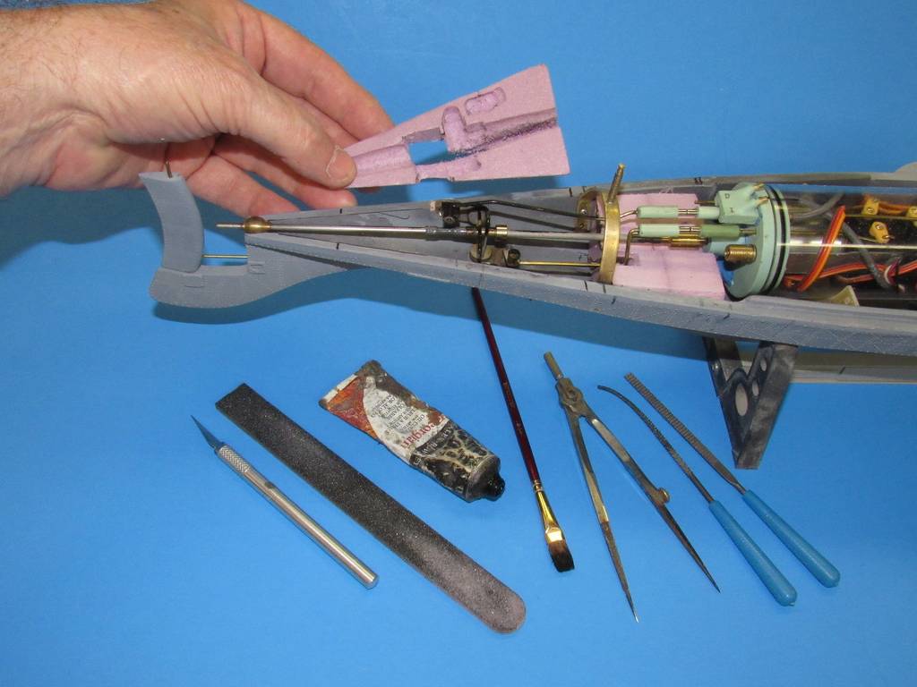
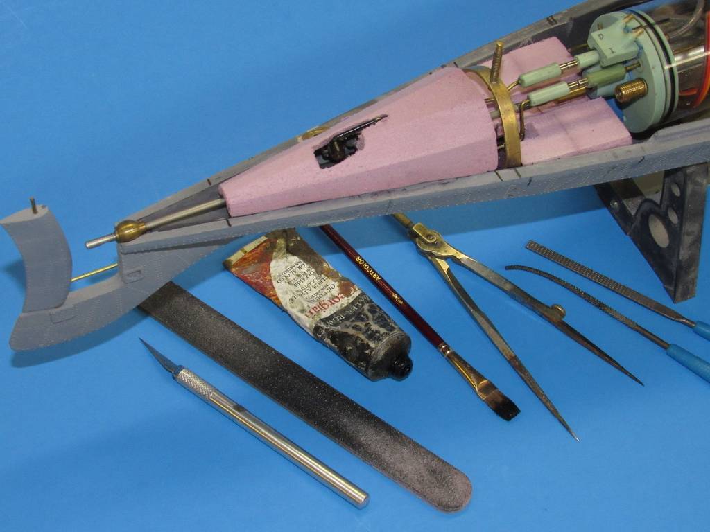
Prop Guard Struts
I wanted to use a set of Prop Guard Struts that were made of a strong material and were constructed to the specifications in the Nautilus Blueprints; specifically 2 mm thick, 4 mm wide with rounded edges. Bob Martin agreed to create the STL 3D Printer file for me as a special order and had Shapeways print 4 of them in bronze. They are very sturdy but they add a lot of weight to the aft section.
At this point I had no idea how to separate the upper and lower hulls. I just knew it had to be done.
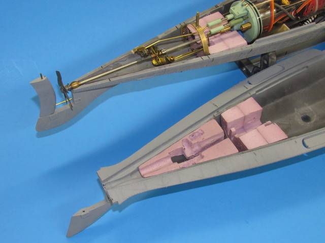
As I was aligning and attaching the Prop Guard Struts to the Prop Guard, I realized that I could cut the Prop Guard right where the Strut connects to it. So, using the Strut as a guide for the razor saw, I cut through the Prop Guard. This gives each section of Prop Guard two points of attachment and the cut isn't very noticeable at all.
-
Skiff
I wanted the Skiff to be removable. At first I used rare earth magnets but I didn't know what kind of stresses might be put on the skiff in water under speed. So I thought I would add a length of 20 test fishing monofilament. But then I realized that if the Skiff came off, the monofilament would foul the propeller, so I abandoned that approach entirely. I decided to hold down the skiff using a brass bolt. A 2-56 brass bolt, but it's only 5/8" long. The hull is pretty thick at that point.
Before the top of the Skiff is attached, I turned it upside down and drilled a hole through the keel at the midpoint into the Skiff's center bench using a drill bit that allows a free-fit for the 2-56 brass bolt.
Then I placed the skiff back into the Skiff Bay and drilled down through the upper hull using the same size drill bit as before.
Then using a drill bit with a diameter as large or a bit larger than the brass nut that fits the 2-56 bolt, you countersink the first hole you drilled about the height of the brass nut; maybe 1/16" to 1/8" inch.
Next, turn over the upper hull. Select a drill bit with a diameter just barely bigger than the head of the bolt. From the underside of the upper hull, carefully countersink the first hole you drilled just until your brass bolt, when dropped in the hole will stick out far enough to reach through the skiff bay and into the skiff and up through the hole in the center bench. Don't drill completely through the upper hull.
Back to the skiff sitting in the Skiff bay with the bolt sticking up. Thread a brass nut onto the bolt and secure the nut down with a little CA glue being careful not to glue the bolt and nut together.
Now you can glue the top to the Skiff and you can just unscrew the skiff if you want to remove it.
Comment
-
Surprised you didn't reinforce the rostrum to protect the wheelhouse or just in case you want to ram something...Last edited by redboat219; 01-08-2024, 11:14 PM.Make it simple, make strong, make it work!Comment
-
Custom Watertight Cylinder
First I tried using a conventional cylinder but I could not figure out how to get everything I wanted into it. I needed more room.
My WTC was constructed of nested polycarbonate tubes with 1/8" walls, purchased from McMaster-Carr.
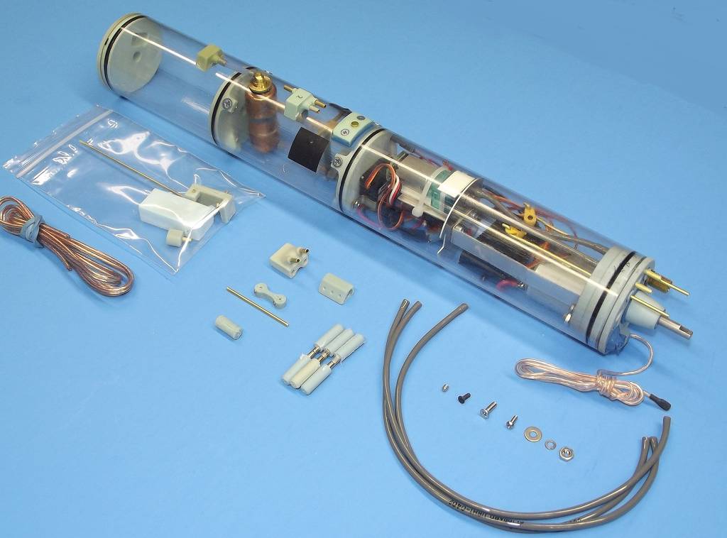
Below you see a picture of my first version of the WTC. When I tested it for trim, it was already right at the correct emerged level, but it rolled badly. I could not add more weight or the sub would never surface. So I had to redesign.
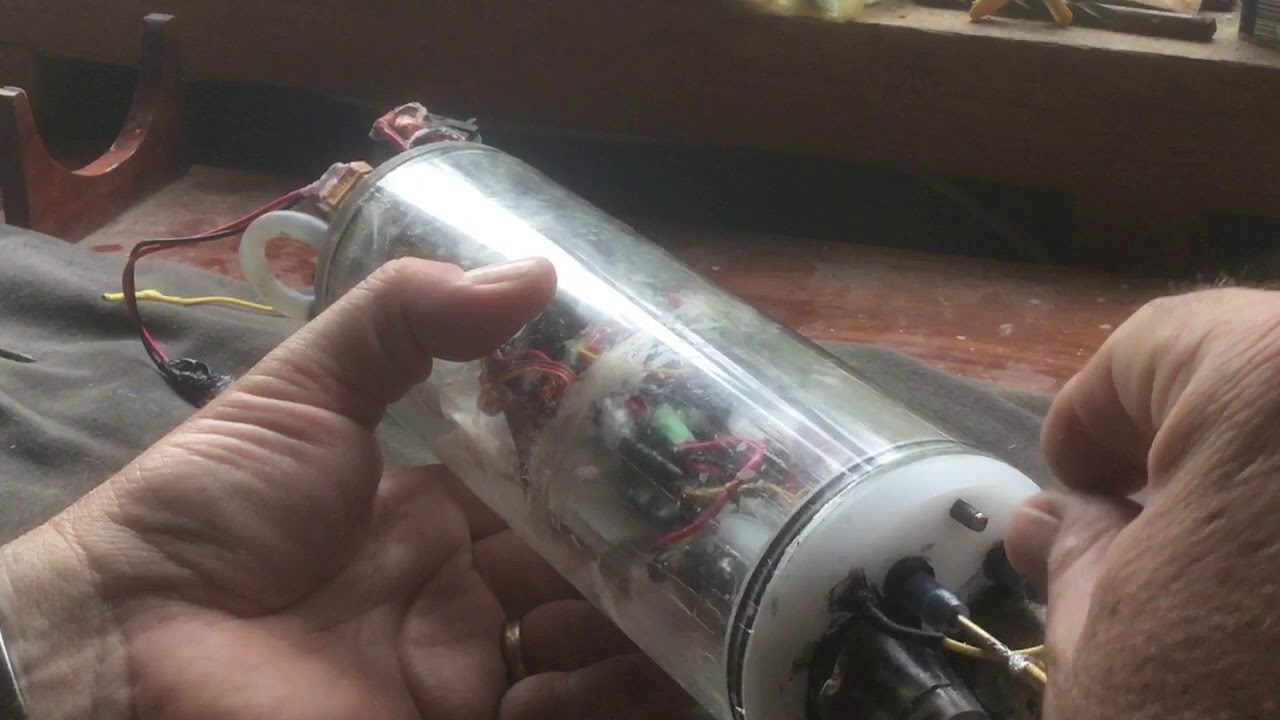
WTC - Current Version (as of Oct2023)
The current version of the WTC has 3 sections; Bow, Stern, and Main Body. The Bow and Stern sections are recessed into the Main Body. Because the tubes nest, water pressure will force the two end sections into the Main Body. The retaining ring prevents that. The retaining ring is about 3/16" long with an OD of 3" and an ID of 2 3/4".
The Bow section is 1 1/2" long with an OD of 2 3/4" with a retaining ring set at 3/4". It is capped with 3/16" thick circle of polycarbonate with a diameter of 2 3/4".
The Stern section is 2" long with an OD of 2 3/4" with a retaining ring set at 1/2". It is capped with 3/16" thick circle of polycarbonate with a diameter of 2 3/4", into which a smaller tube with a diameter of 5/8" and 1 1/4" long has been attached. More details on this later.
The Main Body is 8 7/8" long with an OD of 3".
The overall length of each section is governed by the interior dimensions of the hull. In other words, the Main Body plus the two retaining rings are as long as they can be and still fit in the hull with an OD of 3".
Stern Section
Note the retaining ring in the picture below.
The Stern Section houses the brushed motor, the ESC, and slack wire.
To save as much space in the WTC as possible, I decided to bolt the motor directly to the stern cap. In the photo below it's easier to see. To keep the weight of the motor as close to the keel as possible to help prevent a rolling problem I attached the motor at the bottom of the Stern Section. I used a 5/8" Forstner bit to drill a hole in the cap for the motor's neck and to fit the 5/8" OD polycarbonate tubing that would contain the motor shaft and shaft seal. But I quickly discovered that the neck of the motor would not allow the tube to seat itself down far enough in the cap. So I fabricated an acrylic collar with a laser cutter to help support the 5/8" tube. I also put two holes in the collar for the bolts that would hold down the motor.
But what would I do to waterproof the connection with the motor? I realized that I could use a flat-head bolt, the kind with the funnel shaped head. If I drilled a barely free-fit hole in the end cap for each motor mount, then when I bolted the motor into place the action of tightening the bolt would plug the hole and keep the water out.
Last edited by Johnny Depth; 01-10-2024, 04:29 PM.Comment
-
Go with a constant diameter 2" WTC with a 1/16" wall thickness. Enough volume to house all the goodies yet leaves enough annular space between the cylinder and the inside of the tapered hull. You'll need that space to cram fixed ballast low and buoyant foam high -- only way to significantly distance the vertical c.g. from the c.b. The greater the vertical distance the more powerful the righting forces at work to statically stabilize the boat -- that'll fix your rolling problem.


Who is John Galt?Comment
-
Ballast Tank and Water Pump
I decided to use a High-Pressure Ballast Tank System because the concept is very simple. You just need a Ballast Tank that will take the pressure and a Ballast Tank Water Pump that will provide that pressure.
For two reasons I decided not to use a Solenoid Valve to control the flow of water into and out of the ballast tank.
The first reason was a fail-safe for surfacing the sub if something went wrong. As long as I was actively operating the water pump to fill the ballast tank, the water would remain in the ballast tank. But as soon as I stopped actively operating the water pump, the built-up pressure in the tank would purge the water from the tank and the sub would surface.
The second reason was that I couldn't seem to find a solenoid valve small enough to fit in the WTC. If anyone knows of one, please let me know.
A peristaltic pump would solve the problem of finding a solenoid valve but their pumping rates are slower and their hoses have to be changed frequently to avoid catastrophic leaks.
Ballast Tank Water Pump
After trying several gear water pumps, this one was by far the best for size and strength.
The picture above shows the 12v Pump Dc 3-12v Mini Self Priming Gear Micro Gear Pump for Water with 360SH Motor with the original orientation of the barbed inlet and outlet tubes.
Also shown at the right side are one of the epoxy ballast tank walls and the wiring raceway tube.
There are many vendors selling these pumps and although they all look the same only one in every 6 pumps performed well. I tested one to see how powerful it was. I connected the outlet of one to a small empty plastic water bottle and I placed the inlet in a container of water and started it. I expected the pump to stall at some point but instead it blew the cap right off the bottle.
Reorienting the Inlet/Outlet Tubes of the Pump
It is difficult to see in the picture above but this particular gear pump has one barbed tube sticking straight out the top and one barbed tube sticking straight out one side. When trying to run tubing from the pump to the ballast tank and a tube from the pump to an outside port it can become quite difficult because it seems that there is always one tube that points in the wrong direction. But here's a way to change the orientation of the barbed tubes on the pump.
Pictured above is a Plastic Barbed Tube Fitting For Air And Water, Easy-View 90 Degree Elbow Connector with 5/32" ID or 1/8" ID tubes available at McMaster-Carr.
There are two ways you can modify the direction in which the pump's inlet and outlet tubes point.
One way is to saw off the barbed tube on the right angle connector just above the barb leaving a short length of straight tube. Then you remove the top of the pump by removing the screws. Turn the top over and expand the hole where the barbed tube is located using a drill bit with the same diameter as the tube on the right-angle connector. Then all you need to do is insert the tube on the right-angle connector into the hole in the cap. Orient it as you desire and then epoxy it down.
The picture above shows a right-angle connector inserted into a hole drilled in the top of the pump. At this stage it can be rotated in place 360 degrees to find the best orientation. Then it can be epoxied in place.
The other method is to saw a tube off of the right-angle connector and drill it out. Then cut the barb off of the barbed tube of the pump at the barb leaving a short tube. Then you can insert the tube into the right angle connector, rotate it in whatever direction you need, and epoxy it in place.
At the top of the photo above, the side outlet of the pump, which would normally project straight out from the body, has been redirected downwards (red high pressure tubing) using a right-angle connector. Near the middle of the photo above, the top outlet of the pump, which would be normally project straight up, has been redirected to the side using a right-angle connector.
Tubing for the Water Pump
In this high-pressure system I assume that the tube from the water pump to the external port is low-pressure and that the tube to the ballast tank to be high-pressure. Therefore I chose different types of tubing for each.
For low-pressure tubing I chose 3/16" Clear Vinyl Tubing which can withstand a maximum pressure of 55 psi.
For the high-pressure tubing I strongly recommend the 1/4" OD, 1/8" ID Red Vinyl Micro Fuel Line with a maximum working pressure of 80 psi. This stuff grips so tightly to a barbed tube that if I want to remove it I have to cut it off. In order to attach it I have to dip it in boiling water to soften it enough.
The Ballast Tank
I've used two versions of the Ballast Tank itself. The first was a conventional style ballast tank with fixed walls within the WTC and a wiring raceway. The second, in short, is a plastic water bottle.
Construction of the Conventional Style Ballast Tank
The ballast tank section of the WTC has an ID of 2 1/2" and is about 3 1/4" long, not counting ballast tank walls, which provides 12.76 cubic inches or 209 cubic centimeters. The wiring raceway has an OD of 5/8" and a length of 3 1/4" and a volume of 16 cc. So the ballast tank can hold a maximum of 193 mls of water.
At first I tried to use two 3/16" circles of polycarbonate as ballast tank walls. I positioned them, epoxied them into place and let the epoxy cure for at least 24 hours. Then I did a fill test on the ballast tank. I watched in amazement as the polycarbonate tube itself actually swelled, thereby pulling the wall away from the ballast tank walls followed quickly by catastrophic failure. As I mentioned above, that's a strong water pump.
So I had to find a different method of creating the ballast tank.
Casting Epoxy on Saltwater
By accident I discovered that EasyCast Clear Casting Epoxy can be cast on saltwater. It floats and cures perfectly well with no cloudiness and it's very strong. Maybe other epoxies can too. I don't know.
Making the Ballast Tank
First mark off where you want the ballast tank walls.
Then cut a length of 5/8" polycarbonate tubing a little bit longer than the ballast tank walls. This will be the wire raceway.
Rather than positioning the wire raceway through the middle of the WTC tube, I glued it to the wall of the WTC tube. Simply mark a straight line on the WTC tube where you want it to go such that it emerges on each side of the ballast tank walls. Then place the tube there and epoxy it in place.
To pour the first ballast tank wall you stand the WTC tube on one end and seal it so that water will not leak out. I used a plastic bowl and silicone rubber cement. Then fill the tube to the desired position for the first wall with saturated salt water.
Then I mixed a batch of the EasyCast epoxy as follows:
16.20 grams RESIN
13.50 grams HARDENER
This makes enough epoxy to pour a 1/4" thick wall in the 2.5" ID tube.
Measure the Resin first. When you pour the Hardener, it will float on top of the Resin. If you weigh out too much hardener, you can carefully remove some.
It will harden in 24 hours but I give it 48 hours just to make sure.
For the second wall, you add more saltwater and repeat the process. When you are finished you have a container filled with saltwater. Then you just drill a hole in it where you want your tube and drain out the saltwater. You could also embed your inlet tube and any wiring before you pour the epoxy.
Water Bottle Ballast Tank
I found a small plastic carbonated water bottle that fits in the 2.5" ID WTC tube. I thought it was important to use a carbonated water bottle. I figured that if it was a carbonated water bottle that it must be able to take some pressure.
There was enough space between the water bottle and the inner wall of the WTC tube for the wires from the stern section so I did not need a wire raceway.
I drilled a hole in the water bottle's cap to accommodate a "Plastic Barbed Tube Fitting For Air And Water, Easy-View Connector For 3/16" Tube Id", available at McMaster-Carr, and epoxied it in.
The big advantage of using a plastic water bottle is that the bottle itself can be easily changed by simply unscrewing the cap and replacing the body.
A big disadvantage is that if you pull a vacuum on it, the bottle crushes easily and weakens the plastic.
Comment
-
how about a servo pinch valveMake it simple, make strong, make it work!Comment
-
Here's David Hughes' (Zero Bubble Model Design) Ballast TankMake it simple, make strong, make it work!Comment
-
This ought to be small enough if you want a solenoid. Servo pinch valves also work very well, and cheap to implement.

Regarding the strength of the tank, if you're making it sealed, the endcaps need to be fixed very stoutly. If I assume your tank is 3" diameter, with a 50% filling of the tank pressure will be one atmosphere (14.71psi) which on the endcaps alone will be equal to a tad over 200 pounds trying to push them apart- not insubstantial.
Comment
-
Make it simple, make strong, make it work!Comment
-
3 way valve
When the power is off 1 through 2 , 3 are blocked
When energized 1 through 3, 2 are blocked
Rated voltage: DC 6V / 12V / 24V / 36V
Inlet /outlet aperture:6.2mm
Weight: 95g
The three-way solenoid water valve is commonly used in tea brewing machines, coffee machines, and water dispensers.
DimensionsMake it simple, make strong, make it work!Comment
-
Thank you Subculture. I will follow up on that solenoid.
My ballast tank walls are 1/4" thick and made of epoxy using the casting technique I described earlier. They must be pretty strong because I fill the tank to about 85% to 90% to submerge. In testing I've filled the tank to about 95% thanks to that amazing little water pump. The epoxy shrinks as it cures and I think that might contribute to its strength. I figured the pump would leak first.
Comment


Comment