Excellent. Exactly what I was after. I'll have to rig up some kind of drawing, extrapolating the info from the photos in order to make a scribe plan of some kind.
Bob
-
seni
ng more have to write something
Last edited by Albacore 569; 04-17-2023, 01:36 AM.Leave a comment:
-
Sending all deck photos i have.
Last edited by Albacore 569; 04-17-2023, 01:23 AM.Leave a comment:
-
OUTSTANDING BOB! I deliberately stayed away from this web site for a while & just hoped I didnt upset anyone. The hull looks so beautiful now and the bow plane mechanism looks simplest and very robust like the rest of the hull.
Sending you every photo I have of anything showing the uppr decks close in Since emails seem to not be working, posting every deck photo I have collected for years. I probably have bout every photo in the public area on these boats. Hope these help. Posting here instead of emails for down load.
Last edited by Albacore 569; 04-17-2023, 01:47 AM.Leave a comment:
-
Success!
Honestly, the forward linkages were a mental stumbling block for me, and part of the reason that I kept putting this project on the back burner, which is unfair to Steve, who commissioned the build. Happily, I pushed through last week and successfully integrated two waterproof servos and the sliding retracting bow planes into a functional system.
The bow planes slide in and out of a pair of brass rails. Inward tension is achieved via the use of a high-strength elasticized cable. Extension force is applied via an arm actuated by a waterproof servo. The arm is anchored on the far end of the horn. As the servo spins, the arm pivots about the mounting point until the horn itself is encountered. The arm forces the plane outward, sliding on a brass channel. Moved in the opposite direction, the servo horn rotates, but the arm simply pivots without movement as the opposing dive plane is extended.
Neutral postiion:
Extended position:
Opposite extension:
Here is a video of the system in operation:
Leave a comment:
-
Apologies to everyone. It was a tough day yesterday and I wasn't in a good headspace. I fully understand that this has been an ongoing passion of the customer for a long time and there is a desire to see perfection in the long-awaited finished boat. I'm grateful to be a part of bringing it into fruition.
I successfully engineered the retraction half of the bow planes. It uses elasticized cable and a pulley to keep inward tension on the planes. I drafted and printed servo holders for the two waterproof servos that will be used to extend the planes. The idea is that the extension arm is anchored on the rear half of the servo horn while the forward half has a pin that presses against the arm when the servo swivels. In this way, the arm is under tension when extending, and rotates freely when the opposing plane is actuated.
Taking those comments to heart about hull finish, I spent some time cleaning up the hull split. The boat is ready for sanding again and after a bit of TLC, will be smooth, sharp and ready for additional details.
Steve, do you have any reference materials for the upper deck details? You sent lots of pics of the museum boat, but all are taken from below or beside. I can't see much at all in the way of safety lines, hatches, etc. I'm getting close to scribe time.
I'm off now from today through Tuesday for a much needed vacation with Renee.
BobLeave a comment:
-
It isnt passiv/agressive. Faith in you. Its your emails spam blockers. i am always not recieving emails. I only know this because of we started sendng tet messages instead. I don't like in public either. I agree with Merriman on the earlier Scale ship yard thread. I agree. I'll try & send text messages if I have any questions. but can't being blind. i apologize too. Just been waiting15 years. Letting you work and leavng you alone. thank you for everything.
I agree with you Bob , The bow planes of the 209 and the Arethuse use completely different methodolgy. if I was the French designers in the early 1950's I would have used the 209 methodology.Last edited by Albacore 569; 04-05-2023, 10:05 AM.Leave a comment:
-
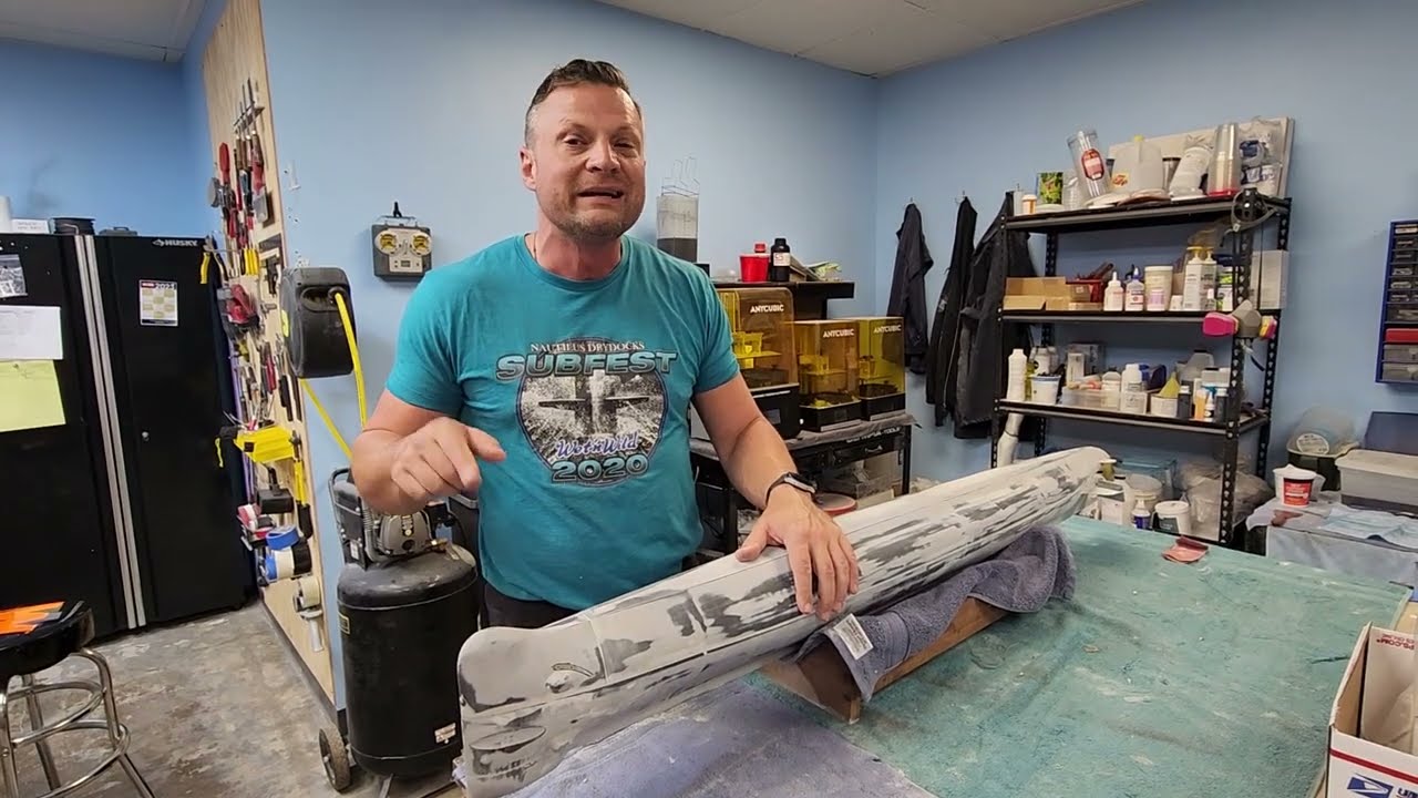
And that... is why I don't like sending in-progress photos of builds to customers. Of course the hull will be post-process and finish-sanded. Methinks I detect a hint of passive aggressive commentary regarding the hull. Then again.. maybe I just haven't had enough morning coffee yet. If the former, please let me work. If the latter, well then I apologize. Fresh coffee is in my cup as we speak.
Absolutely not applicable to this design. The 209 swivels out, the Arethuse slides. Completely different methodology and with infinitely more challenging movement.The German design seems similar in function (but to me) much simpler. Again two fixed curved triangular foils opposite sides, on a vertical axis swinging in or out. one on a fixed up angle varying the surface area, and a down angle one on opposite side.
Perhaps more applicable, just not feasible. I literally have about 1/8" of surface area on the plane to work with. Retracted, it butts tight against the hull. When extended, only about 1/8" of the forward edge is accessible.Originally posted by Subculture
I have zeroed in on a strategy that involves a pair of servos with an arm, one per plane. The planes are pulled inward by a high-strength elastic cable. The servo pushes to get them to extend. I'll have pics later today and we'll see if the solution is feasible. I have a backup if it doesn't work out.
Leave a comment:
-
I'd look at a scotch yoke mechanism, perhaps with two servos mixed in transmitter, although it could use a single servo. https://en.wikipedia.org/wiki/Scotch_yokeLeave a comment:
-
Thank you Bob for the Photo progress images. After the bow planes are done and operating well, Hopefully the hull will be sanded and crisped up with sharper crisp smooth surface lines. The hull sections definitely looks robust as you described.
The German planes are similar in function and location, but different in engineering execution. Elegant thing is when either plane isnt actuated, the hull should be clean of control empennages in the bow.. To rise (depth not angle) , you extend the starboard upper plane and a fixed curved foil emerges varying the degree of rise by the amount of surface area becomes exposed or reduced. The opposite for the lower port plane. exposing the lower plane only to descend.
The German design seems similar in function (but to me) much simpler. Again two fixed curved triangular foils opposite sides, on a vertical axis swinging in or out. one on a fixed up angle varying the surface area, and a down angle one on opposite side.
you tube actuation of rc model 209 bow planes.
https://www.youtube.com/watch?v=MEdp0qNVidg
On both the French and German designs of the same period. the area of the bow planes themselves are small. But they are on both sub designs on the end of long moment arms dynamically for pitch function, so small is acceptable. Will see....how they work in the water on the model.Last edited by Albacore 569; 04-05-2023, 01:44 AM.Leave a comment:
-
Wow! I didn't realize there was such a distance "gap" between the 2 planes. Is there similar for the Type 209 German? Perhaps there's some part of that mechanism that can be adapted, of course assuming someone's done the 209 with properly operating bow planes!?Leave a comment:
-
Back at it in earnest.
The cylinder driving this boat will be a brand new OTW 3.5" unit with 12" ballast tank. It will be outfitted with pitch control and depth-keeping as well as a remote on/off switch. Jason is 80% done the installation of these electronics and should be done that today if things go well.
The forward planes are proving to be problematic, though I plan more work today to try and work out the mechanism. At this point, the hardware for the sliding planes are installed and working perfectly. Both upper and lower planes extend and retract along their rails perfectly smoothly. All that remains now is to work out how to actually make them move.
The challenge to this is that, when retracted, the planes are tight against the inside of the hull, and when extended, nearly fully pushed outside the hull. I have, maybe, 1/8" of real estate to work with, particularly on the lower dive plane, which sits in a much narrower part of the hull.Attached FilesLeave a comment:
-

Leave a comment: