Welcome to our forums. For the best in R/C submarine kits, components and accessories, be sure to visit the Nautilus Drydocks
If this is your first visit, be sure to
check out the FAQ by clicking the
link above. You may have to register
before you can post: click the register link above to proceed. To start viewing messages,
select the forum that you want to visit from the selection below.
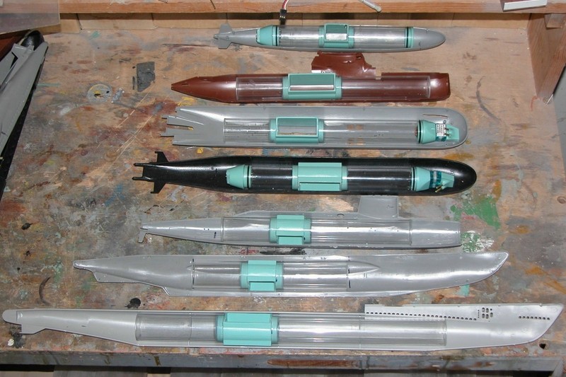
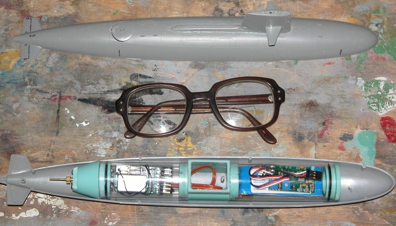
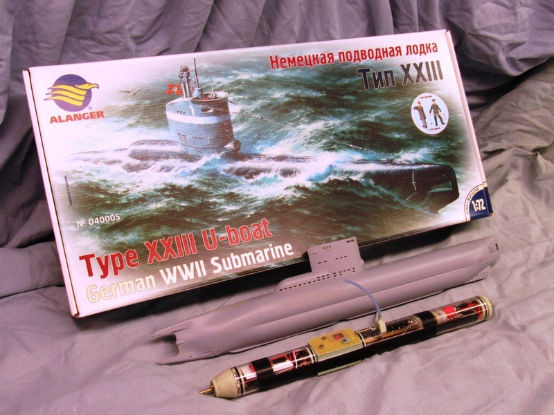
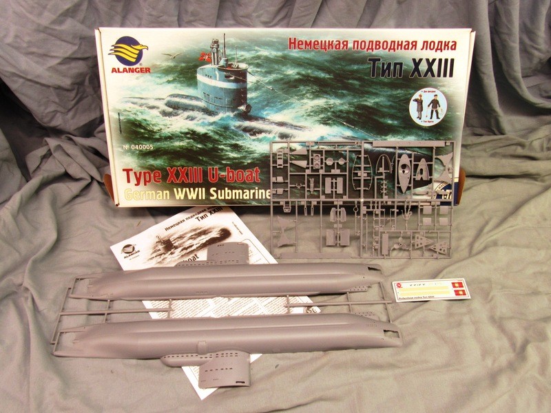
Agreed but I haven't seen the small ones before. With all of the small scale Russian subs and their narrow behinds being made at the minute and the 1/144 Jimmy Carter of this thread they strike me as particularly apt at the minute.
Agreed but I haven't seen the small ones before. With all of the small scale Russian subs and their narrow behinds being made at the minute and the 1/144 Jimmy Carter of this thread they strike me as particularly apt at the minute.
I'm sitting here with a cup of coffee having a think.
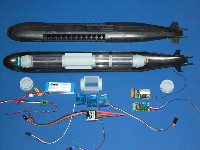
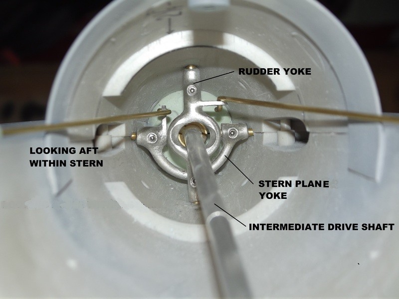
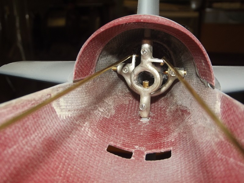
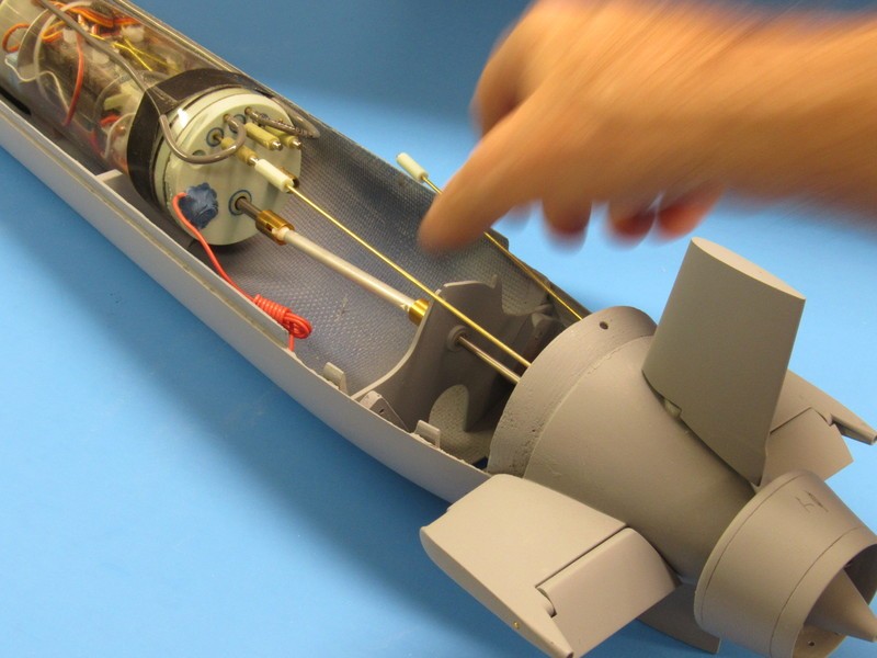
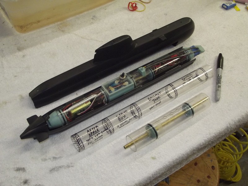
Recently I've made some incremental, but significant progress on JC. I'm mostly down to rigging the dive planes and hooking up the prop, and then it'll be fit to run and test under power. I took a cue from Bob and, due to the limited space in the tail of the Seawolf, and the way I built it, I've opted to connect the rudders further forward, closer to the WTC. After some doing, and swearing, I have both the rudders connected and moving in sync, but I fear I may have painted myself into a bit of a corner and not allowed enough room for my stern plane linkages. The original idea was to configure the linkages like I did for the rudders - with a clevis on the end of the servo pushrod clipping onto a little brass arm that's silver soldered onto the collar.
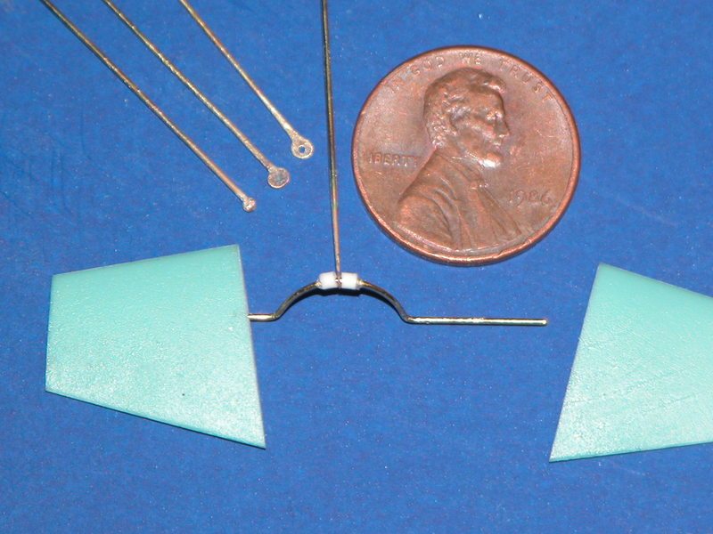
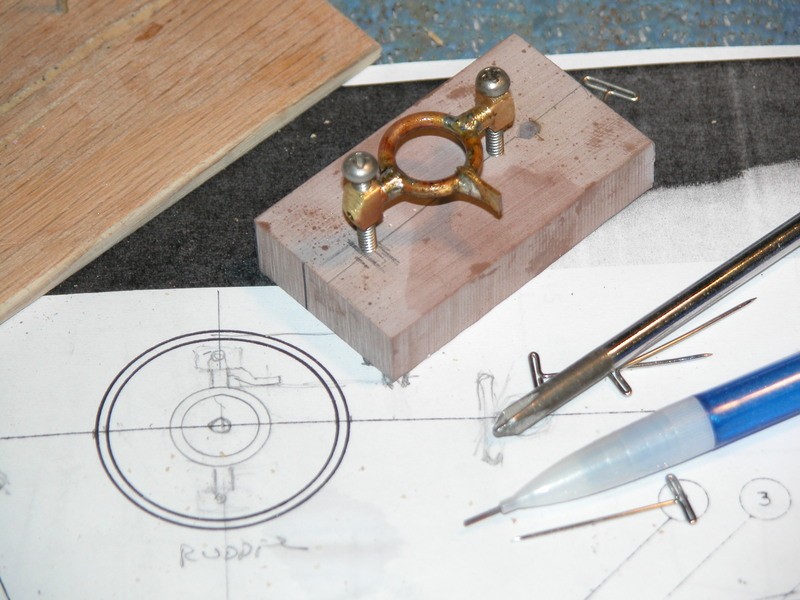
My thought at the moment is to go the route of the D&E Seawolf fittings kit, and other designs I've seen of Davids, and connect the stern planes with something similar to the sketch I've attached. The connecting half-circle of brass would need to be relatively thin and small. I'm thinking maybe 1/8" brass like I've used on the control surfaces. The boat will have operating bow planes, and the sterns will be hooked up to an angle-keeper. I seem to remember hearing somewhere that the stern planes really only need about 5-10 degrees +/- of rotation, vs the approx 30 degrees +/- for the rudders.
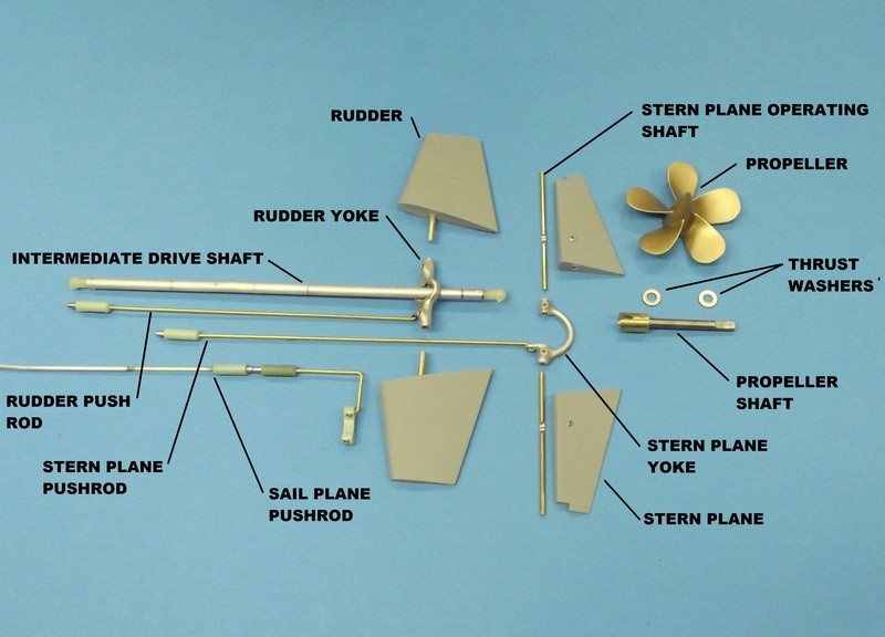
Some other dimensions worth mentioning:
* Propshaft = 3/16"
* Control surface shafts = 1/8"
3/16" drive shaft is way, way too beefy for this model. Go with 1/8" diameter drive shaft. That will give up formerly lost space to ease the crowding at the tapering tail-cone.
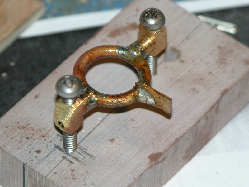
Also, the U-shaped element of the stern plane yoke can be 1/16" brass rode. Again, less space-taking. At 1/144 your SEAWOLF does not impose much torque on drive shaft or yokes. Don't over-engineer back there!
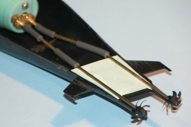
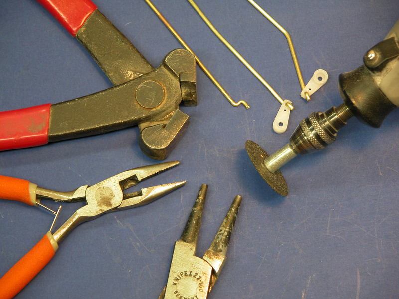
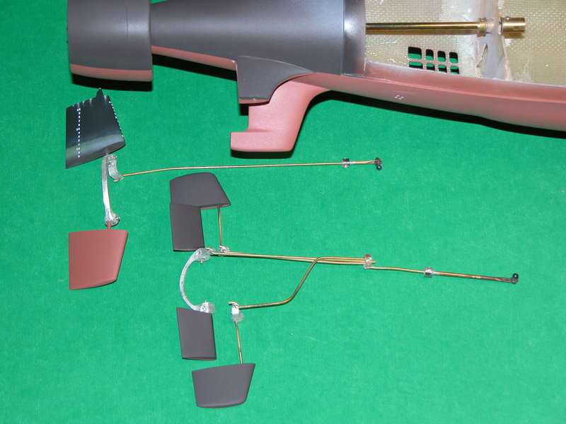
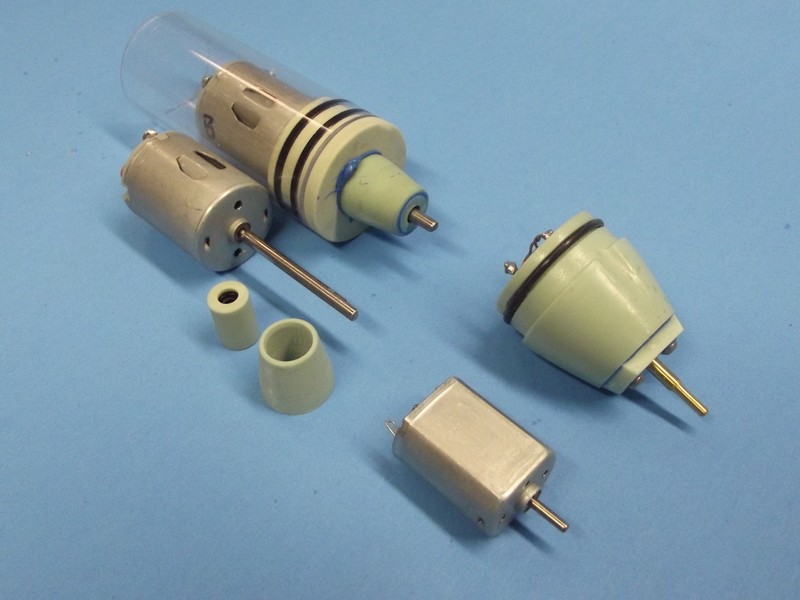
Some pointers on running gear and yoke fabrication:
I'm sitting here with a cup of coffee having a think.
Recently I've made some incremental, but significant progress on JC. I'm mostly down to rigging the dive planes and hooking up the prop, and then it'll be fit to run and test under power. I took a cue from Bob and, due to the limited space in the tail of the Seawolf, and the way I built it, I've opted to connect the rudders further forward, closer to the WTC. After some doing, and swearing, I have both the rudders connected and moving in sync, but I fear I may have painted myself into a bit of a corner and not allowed enough room for my stern plane linkages. The original idea was to configure the linkages like I did for the rudders - with a clevis on the end of the servo pushrod clipping onto a little brass arm that's silver soldered onto the collar.
My thought at the moment is to go the route of the D&E Seawolf fittings kit, and other designs I've seen of Davids, and connect the stern planes with something similar to the sketch I've attached. The connecting half-circle of brass would need to be relatively thin and small. I'm thinking maybe 1/8" brass like I've used on the control surfaces. The boat will have operating bow planes, and the sterns will be hooked up to an angle-keeper. I seem to remember hearing somewhere that the stern planes really only need about 5-10 degrees +/- of rotation, vs the approx 30 degrees +/- for the rudders.
Some other dimensions worth mentioning:
* Propshaft = 3/16"
* Control surface shafts = 1/8"
No, it will work fine with just the stern planes. I just like the precision of practical bow planes. The CARTER is a long boat -- might find bow planes more of an asset than the standard SEAWOLF.
You can drill out that Bondo, install a new seal, and get that servo back in there. Or I can send you a replacement motor-bulkhead and you can shift everything to that. Your call.
David
After I posted, I kept digging through the forum history and caught a post where you mentioned that the SD comes with a couple of extra seals. Keeping in the theme of things I pounded the desk with my fist and exclaimed, �You son of a b*tch!� with a wide smile - ala Jack Ryan.
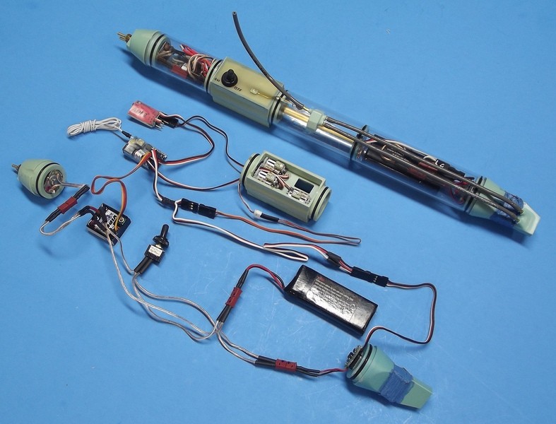
On a slightly more serious note, thank you for your kind offer of a replacement end cap. I may still take you up on one some day, but I decided to be bold. Never underestimate the power (or blind luck) of a determined man and his 12v Milwaukee drill. I bored out the offending seal, tapped a new one into its place, and sealed up the end with a touch of RTV. I think the gods decided to be merciful, and I now once again have a functioning 4th servo in the WTC. I�ll leak check it tomorrow, but I�m encouraged.
I realized that I ****ed something up a while back without even being aware of it. This entire time, I was under the impression that bow and stern planes could be mechanically linked. Now I see that's the exact opposite thinking. I've stared at that damn picture in the Seawolf cabal report a hundred times, and somehow I missed that the bow and stern planes were controlled by different servos. In an attempt to make the design work to fit the needs of my boat,I removed the spare servo and filled the hole in the rear of my WTC. Why? I needed more room inside the WTC, and removing the servo seemed like the best way to do that.
It's painful to write that now, but I'll fess up. It's been done. Without replacing the entire end cap, is there any way to come back from that and make a new penetration with a seal? I've got an angle-keeper, but does this model need functioning bow planes?
No, it will work fine with just the stern planes. I just like the precision of practical bow planes. The CARTER is a long boat -- might find bow planes more of an asset than the standard SEAWOLF.
You can drill out that Bondo, install a new seal, and get that servo back in there. Or I can send you a replacement motor-bulkhead and you can shift everything to that. Your call.
I realized that I ****ed something up a while back without even being aware of it. This entire time, I was under the impression that bow and stern planes could be mechanically linked. Now I see that's the exact opposite thinking. I've stared at that damn picture in the Seawolf cabal report a hundred times, and somehow I missed that the bow and stern planes were controlled by different servos. In an attempt to make the design work to fit the needs of my boat,I removed the spare servo and filled the hole in the rear of my WTC. Why? I needed more room inside the WTC, and removing the servo seemed like the best way to do that.
It's painful to write that now, but I'll fess up. It's been done. Without replacing the entire end cap, is there any way to come back from that and make a new penetration with a seal? I've got an angle-keeper, but does this model need functioning bow planes?
Roger that. The plan was to basically copy your design for a bushing ahead of the stern yokes with a 1/4� piece of 3/16 ID Oilite smushed into a styrene sleeve bored out so it�ll be snug. I�ve retained the lower hull piece�s.... face? Whatever you cut off of the top one to make room for everything.
Good idea on the washer on both sides of the after bearing. Provided I can fit the damn thing in there without having to cut the forward plastic bearing out. Maybe it�s unnecessary.
I shall leave my sacrifice at the altar and back away slowly, now.
You know, if your damned fittings kit were still available we wouldn't be in this situation to begin with! :D
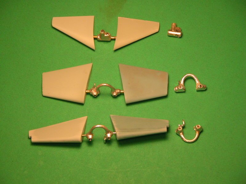
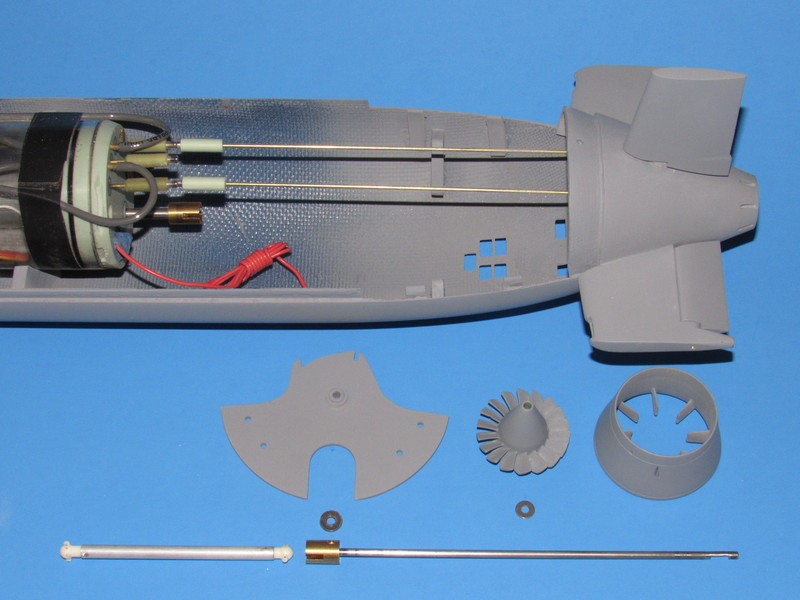
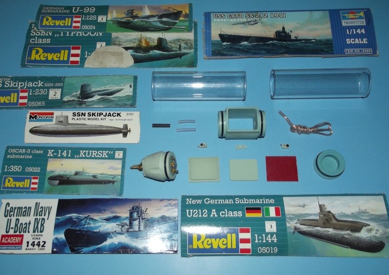
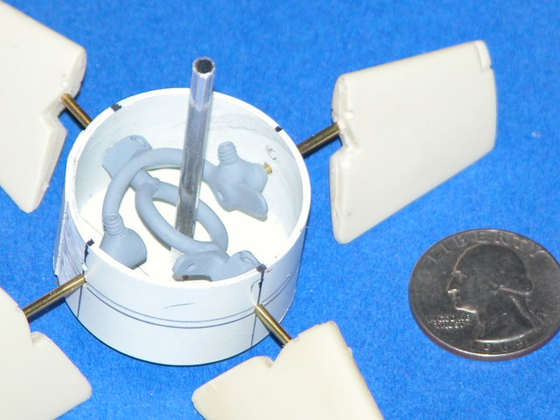
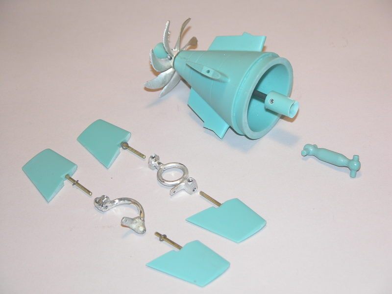
I've attached a sketch that shows the individual pieces in exploded form. Hopefully that clears up some of the confusion. I don't honestly know why he's included the opening for a shaft down the middle, but it seems like enough material for me to work with. Worst case, we improvise. That's half the fun, right?
Oh, hell! I had it wrong.
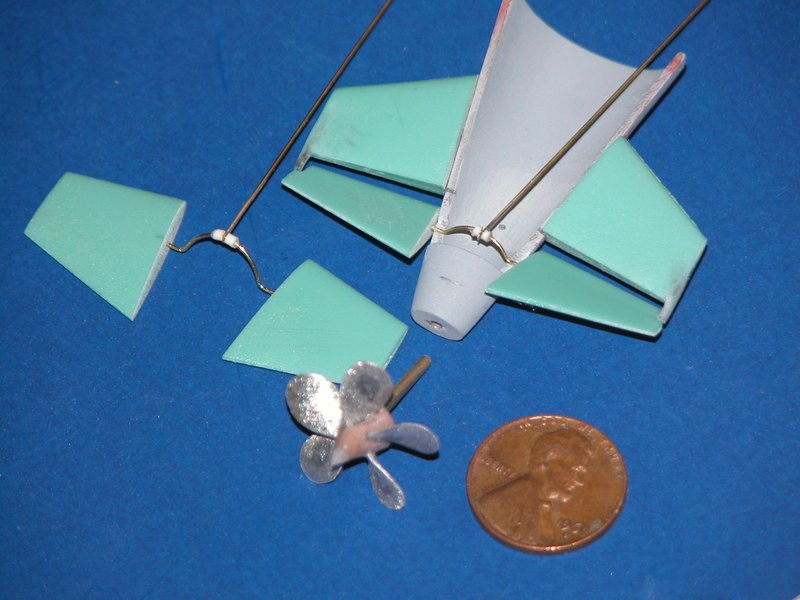
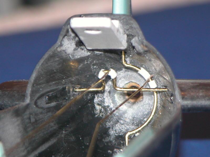
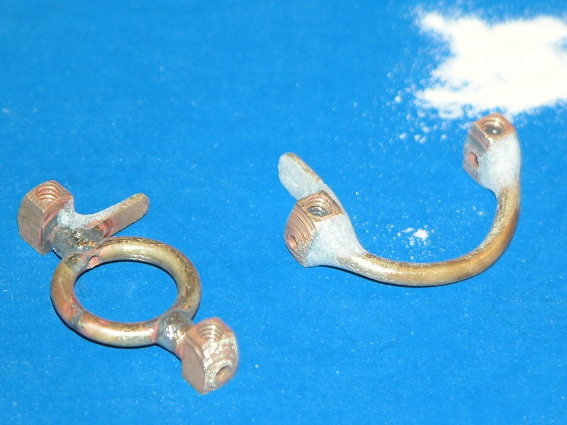
That piece is the forward 'pre-swirl' type stator with bearing foundations. I assume you glue that to the ass-end of the hull and it forms the transverse-thrust bearing for the rotor shaft. Yeah, those two concentric circles are the bearings. Just bore them out enough to make a non-interference fit to the shaft, place a thin stainless washer between the after bearings face and forward face of the rotor hub. This will transmit the ahead thrust load to the hull. And you're in business.
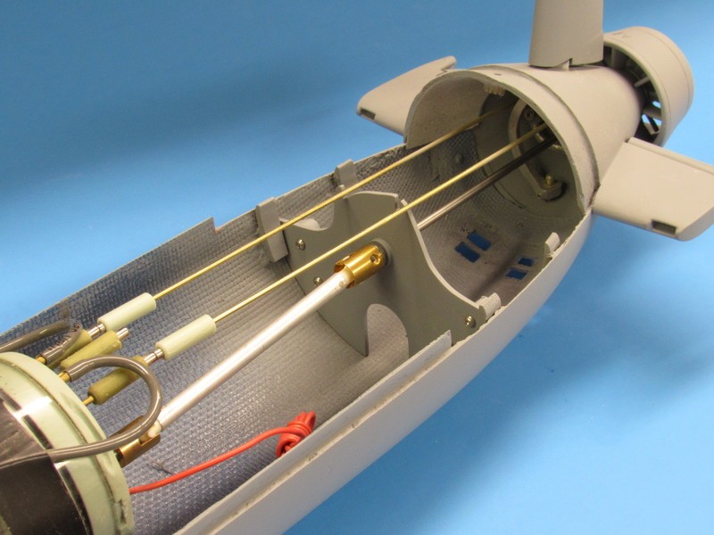
You'll need to fabricate a G-10 half frame just forward of the stern control surface yokes and equip it with a bearing. A wheel-collar secured to the shaft and positioned at the forward end of the astern bearing, with a stainless washer between them, takes care of the astern thrust loads. Something like this:


Leave a comment: