
From the deck down to the long longitudinal breaks between it and the pressure hull is the missile deck. This superstructure originates back aft where it rises up off the pressure hull into a turtle-back, and then runs forward, covering the missile battery, under the sail, to nearly the bow where it transitions into the forward ballast tank group. The missile deck is of uniform height and shape forward of the turtle-back to the sail.
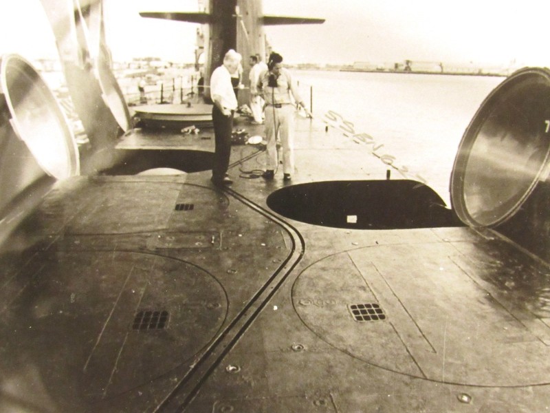
Being a free-flooding structure the missile deck has long, wide �slits �beneath it port and starboard, down were the superstructure meets the pressure hull. It is through these long running slits that water floods and drains as the submarine assumes submerged or surfaced trim. But, when water comes in and out, air has to be displaced or take the waters place. And that�s the job of the many relatively small, square arrayed vent holes set into the deck along the entire length of the missile deck. You can clearly make out some of the vents, one per missile tube muzzle hatch fairing, in the below picture.
With post-war American submarines, most of their exterior structure is broadly characterized as pressure hull or superstructure.
Pressure hull is just that: the high tensional strength steel vessel that keeps the water and critters away from the crew. Incidentally, the only pressure hull you see on a surfaced boat like the WEBSTER are the engineering spaces, well aft of the turtle-back.
All other major exterior structures above the waterline are free-flooding, superstructure. On a missile boat the largest piece of superstructure is the casing that protects and streamlines the missile tube muzzle hatches, conduits, piping (pneumatic, hydraulic, and diesel exhaust-induction), and other items exterior of the pressure hull, but requiring enclosure.
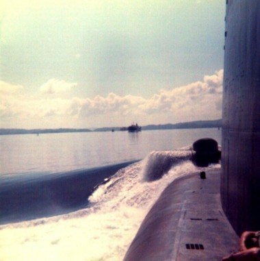
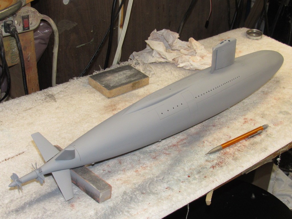
The sail is the next largest piece of superstructure. And, in the unique case of the DANIEL WEBSTER (the subject of this kit-assembly WIP), that big wart at the bow which mounts the bow planes and is kicking some water as the boat makes about five-knots in calm water in the below picture: yup, that�s superstructure as well.
Each deck vent array comprised twelve square holes set in a square pattern. I employed a cheat here as the actual holes in a vent array would have, at this scale, been about .015� square. Not possible if working directly through the GRP structure of the models missile deck, but doable if acid-etched inserts were employed; something I considered, but rejected as at that size, once the deck got wet, surface tension would have blocked any venting of air as I attempted to dive the model after it got wet from a preceding dive. Those vent holes had to be practical. After all, what I�m assembling here is going to be a practical, well running, radio-controlled model submarine. Water molecules just won�t shrink or change their physical properties, no matter how nice you ask them!
So, as a cheat, I simply opened up square holes, each hole representing an array of the smaller holes seen on the real boats. Not scale. And ugly. Sue me!
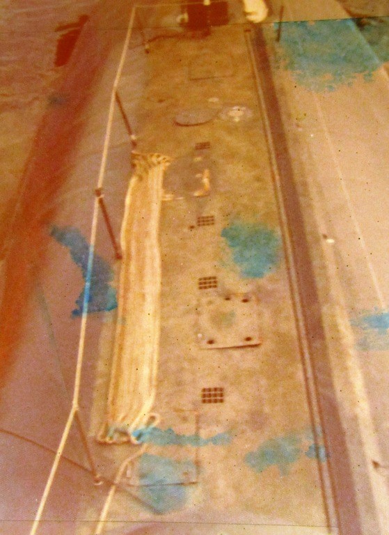
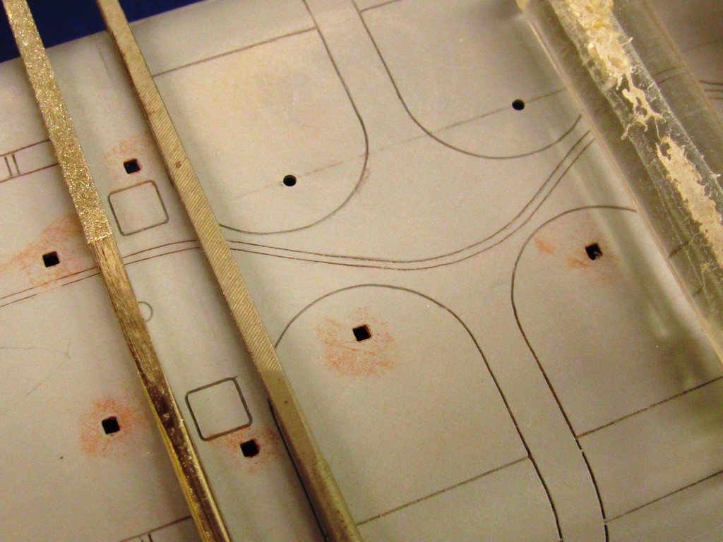
This is the free-flooding deck forward of the sail. The twelve-hole vent arrays can be seen clearly here, this shot taken from the bridge atop the sail before a QM chased me away.
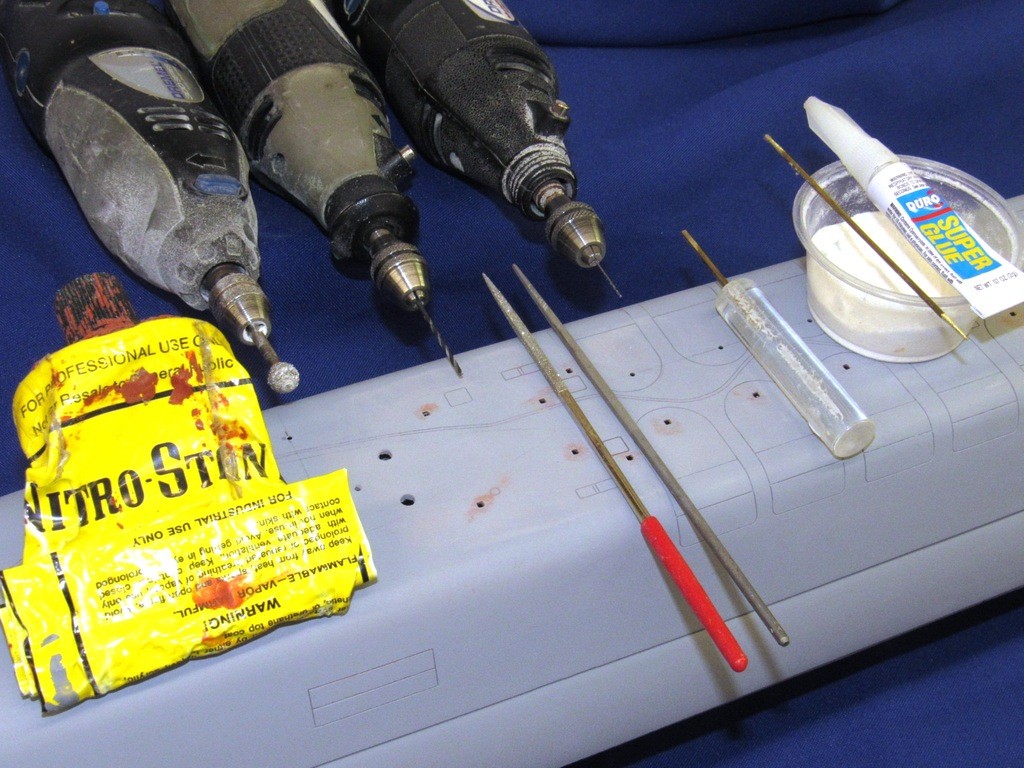
Below you see some starter holes and finished square holes along with most of the tools and consumable.
So, how to make square holes?
Well � duh!
I started by plotting all the locations on the deck and atop the bow plane wart where vents would go. I punch-marked each location with a scribe tip, then drilled a .010� pilot hole at each location. That followed with a .070� bit � as that was just large enough in diameter to pass the tapered point of a square-file, which was used to get a good start on the shape of the hole.
The finished square holes would be just shy of .090� X 0.90�. First, using a diamond studded square file, I ground away most of the remaining glass fiber. I then switched to a more traditional high-carbon, single-cut square file to finish the rough work, getting the square holes to about .095�. Yes. Over sized. Read on �
This Scale Shipyard kit (my copy is decades old) is a very handsome piece of glass work: Nominal wall thickness of the hull proper � and in this context I�m describing the entire structure, less the sail � is about .080�. Thick enough to be reasonably rigid, but thin enough for the above waterline structures not to displace more than a reasonable amount of water.
As a practical matter for these .090� square vent holes to easily pass air in and out of the superstructure it�s desirable to keep the depth of these holes as shallow as possible. So, from the inside of the hull I ground away material under each hole (before squaring them off) with a Carbide round burr, all the way up till I hit gel-coat. This not only reduces the possibility of water blocking the holes, it also presents a more �scale� appearance when looking down into the square vent holes.
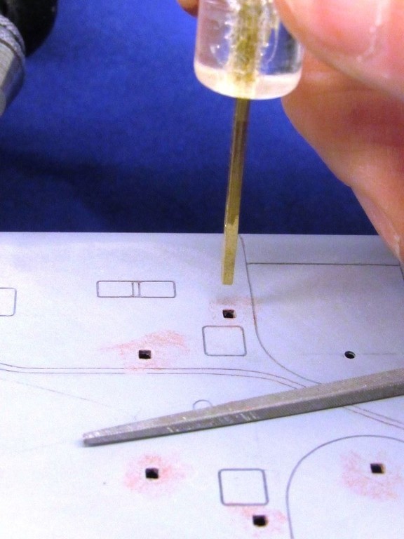
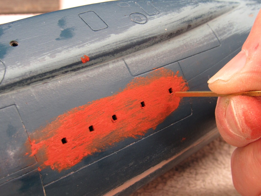
No matter how careful I was with the square file, the �squarness� of the holes just did not look right: the hole corners had a slight radius, and the edges were a bit curved. The solution was to square-file the hole a tad over-size, build up a malleable material along the inside edges of the hole, and to apply pressure within the hole with the aid of a slightly tapered square mandrel to mash the malleable material to shape.
The mandrel is a K&S brass square tube measuring .093� X .093� X .093� X .093�. A short length of that tube set into a round piece of Acrylic rod for easy handling. With great care the flats of the square tube, near its tip, were tapered down to about .085� � that gave me, mid-range on the tapper, the desired .090� square section.
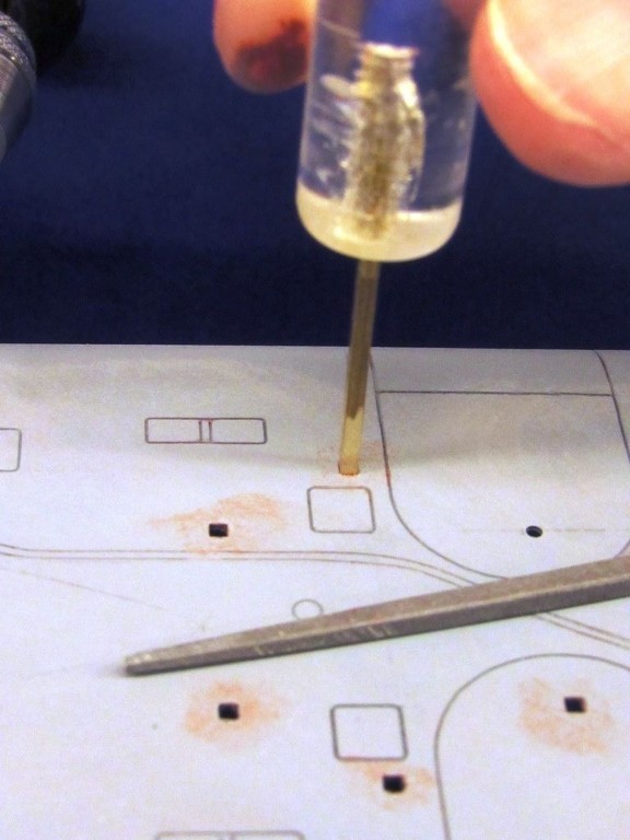
After the initial ramming to shape the mandrel was pull out, a dab of Nitro-Stan swirled into the square hole, the mandrel wetted with a little spit, and the tool rammed home one more time to force the putty anywhere not completely filled by the CA-backing soda grout. A quick block sanding of the holes surface and I moved on to the next hole.
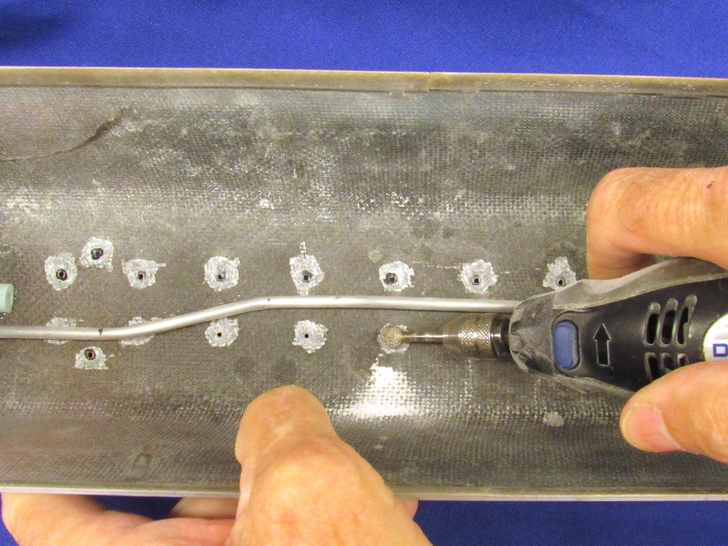
Here, as I was assembling a 1/96 scale kit of the USS ALBACORE, an array of flood-drain limber holes are being given their final square form using the same technique described above.

Comment