Scratch Build Project 685 Plavnik K-278 Komsomolets NATO: Mike

Collapse
X
 
  • Time
  • Show
Clear All
new posts

  • Davidh
    replied
    Thanks for the write up David,

    Learned a lot from that. I have yet to set up a drill / grinder set up at an angle to do the slots for the blades like what you have done there. In a week where I was focussed at least in a model sense on getting the propellers for the mike done, However, I got all fired up to re-tool the Resolution after seeing some efforts done on a 1/96 resolution over at the Subcommittee website. There is a really nice Resolution class taking shape over there and it's inspired to me to address some of the issues that I've discovered with my own...

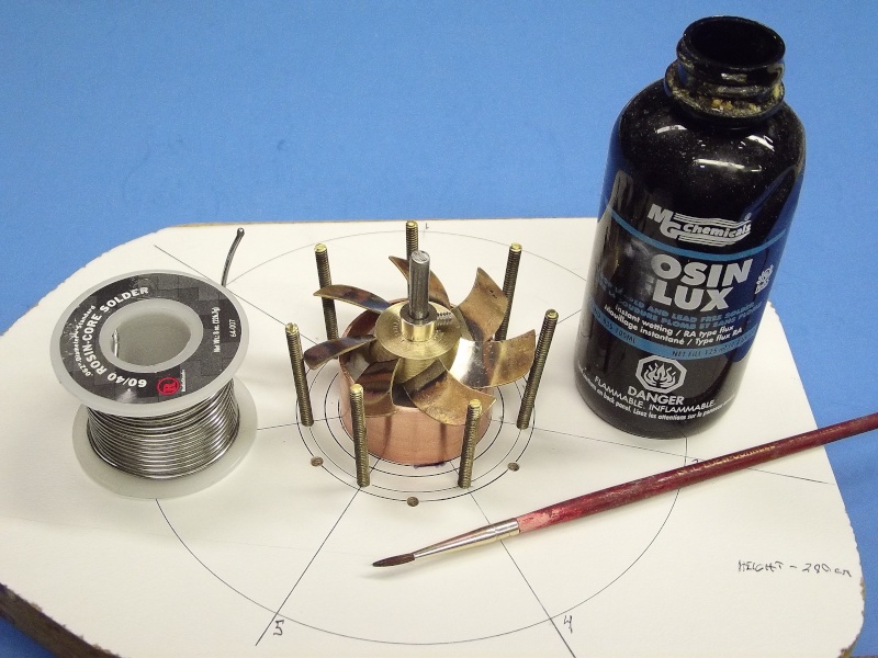
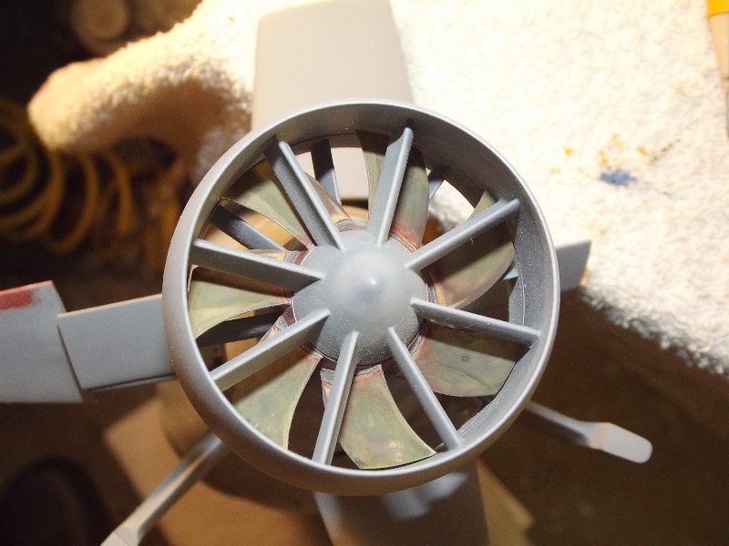
    Anyway back to the prop. The jigs that I turned up on the lather have been excellent. I then turned up two brass bosses, one, the inner shorter one for the inner screw and the outer one with the longer stators attached. Attached a centre drill into the live tailstock and drilled a 3.5 mm hole. then placed an M4 tap in the tailstock and manually turned the lathe chuck onto the tap to create a nice 4mm thread for the prop shaft. Worked well.

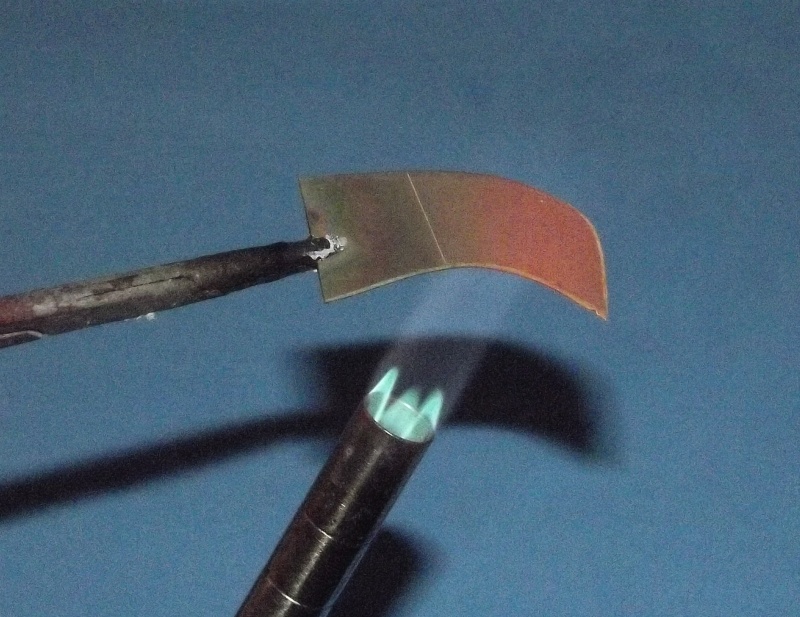
    Then it was time to mark out and cut the angled grooves for the blades to slot into the boss. This was marked up and carefully done with a hacksaw. I know I need a proper set up and eventually will get something up and running. Once this was done it was simply the case of putting all the blades and boss into the jig and soldering. It has taken me a while to get the hang of soldering like this. the right solder makes a difference and with a clean soldering iron and the right temperature it was staring to flow. I am still not great at soldering and there would be the need for some sanding and filing here and there. Eventually when I am happy I will look into the making of the silicon moulds for these two props.

    David H
    Leave a comment:


  • Davidh
    replied
    Click image for larger version

Name:	_DSC4988.JPG
Views:	144
Size:	45.2 KB
ID:	112866 Click image for larger version

Name:	IMG_3041.JPG
Views:	126
Size:	28.5 KB
ID:	112867 Thanks for the write up David,

    Learned a lot from that. I have yet to set up a drill / grinder set up at an angle to do the slots for the blades like what you have done there. In a week where I was focussed at least in a model sense on getting the propellers for the mike done, However, I got all fired up to re-tool the Resolution after seeing some efforts done on a 1/96 resolution over at the Subcommittee website. There is a really nice Resolution class taking shape over there and it's inspired to me to address some of the issues that I've discovered with my own...

    Anyway back to the prop. The jigs that I turned up on the lather have been excellent. I then turned up two brass bosses, one, the inner shorter one for the inner screw and the outer one with the longer stators attached. Attached a centre drill into the live tailstock and drilled a 3.5 mm hole. then placed an M4 tap in the tailstock and manually turned the lathe chuck onto the tap to create a nice 4mm thread for the prop shaft. Worked well.

    Then it was time to mark out and cut the angled grooves for the blades to slot into the boss. This was marked up and carefully done with a hacksaw. I know I need a proper set up and eventually will get something up and running. Once this was done it was simply the case of putting all the blades and boss into the jig and soldering. It has taken me a while to get the hang of soldering like this. the right solder makes a difference and with a clean soldering iron and the right temperature it was staring to flow. I am still not great at soldering and there would be the need for some sanding and filing here and there. Eventually when I am happy I will look into the making of the silicon moulds for these two props.

    David H
    Click image for larger version

Name:	_DSC4990.JPG
Views:	120
Size:	46.0 KB
ID:	112863 Click image for larger version

Name:	_DSC4992.JPG
Views:	122
Size:	47.3 KB
ID:	112864 Click image for larger version

Name:	_DSC4999.JPG
Views:	123
Size:	49.8 KB
ID:	112865

    Leave a comment:


  • He Who Shall Not Be Named
    replied
    Back for more, huh! I can't beat you into submission? You won't quit, will you!!!!

    Good!

    Now, about scribing in wood:

    What makes wood such a bad substrate for scribing is that it has a grain that will act on a traveling engraving tool differently depending on the aspect of the grain to the direction of tool travel -- going with the grain is easy. Crossing the grain is tough. Engraving a curved line subjects the traveling tool to varying resistance as it makes the curve -- effecting width, and depth of cut. The grain will also pull the tool away from the inside edges of your scribing template.

    If you're master is wood, fine, what you do is gouge out those areas that will have engraved lines. Make the gouged areas 1/16" deep and 1/8" wide. Come back with some laminating resin and fill those gouged areas and let cure hard. File and sand the plastic areas flush with the surface of the hull. You now have substrate that will be most receptive to the cutting action of the scratch-awl tip.

    Some tips for a propeller fabrication jig:


    Leave a comment:


  • Davidh
    replied
    Hi Scott,
    Hope this works.

    http://zerobubblemodeldesign.jimdo.com/

    Did you get my text message

    Leave a comment:


  • Davidh
    replied
    Hi Scott,

    http://zerobubblemodeldesign.jimdo.com/

    Hope this works. Did you get my text message?

    Dave

    Leave a comment:


  • HardRock
    replied
    Nice jig. Where is the site for the Mike?

    Leave a comment:


  • Davidh
    replied
    Click image for larger version

Name:	IMG_3034.JPG
Views:	162
Size:	12.6 KB
ID:	112762 Click image for larger version

Name:	IMG_3036.JPG
Views:	124
Size:	17.1 KB
ID:	112763 Click image for larger version

Name:	IMG_3037.JPG
Views:	124
Size:	18.0 KB
ID:	112764 Click image for larger version

Name:	IMG_3039.JPG
Views:	119
Size:	33.5 KB
ID:	112765 Ok,

    So everybody probably thought this build log was dead. I could have left it there, however I don't give up that easily. OK David so, ..hit me for more scribing gems, just remember I haven't got Renshape, as much as I would like it, the nearest supplier is in WA. (perth) 4000 kms away` and I can't seem to get a reasonable quote for the stuff. So yes, it's wood I'm dealing with...
    Mike has only had one or two outings, She did manage to successfully get caught in algae in Scott's pond!

    Propellers...

    The Mike has a really unusual Propeller arrangement as mentioned previously here. The only other subs that have the same arrangement that I can think of is the Victor III class. It is made up of two 4 bladed propellers skewed at about a 45 degree angle to each other. They are not contra rotating. You are not going to be able to find this screw off the shelf so to speak. So a fabricated one is in order. I will be making it for production so I will be making silicon moulds of this sucker. It will be four pieces in the overall moulds as I am creating the design as two separate propellers. It will give me a good opportunity to start using my new lathe. Building a propeller is a skill area I have wanted to develop for a long time. My last attempt at building a prop was my pumpjet propulsor design for my Astute from 2011. That was spectacularly ..average..

    I have been looking at Bart (BWI)'s write up on his Akula class and looking intently at his propeller design and fabrication. Given me lots of ideas and thoughts about how to do it myself.

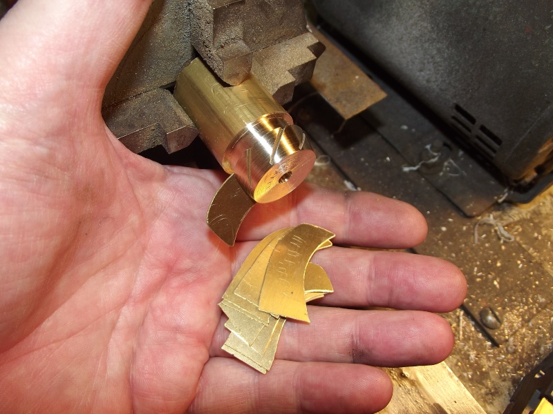
    So I have started to turn a nice piece of brass on the lather to make the rear hub. I drilled a 3.5mm hole in the rear end and then rotated my chuck to cut a thread with a 4mm tap. This gave me the thread I need. Then parting off. I am finding this is probably the least enjoyable part of the exercise. Still it's easier to part brass that mild steel.

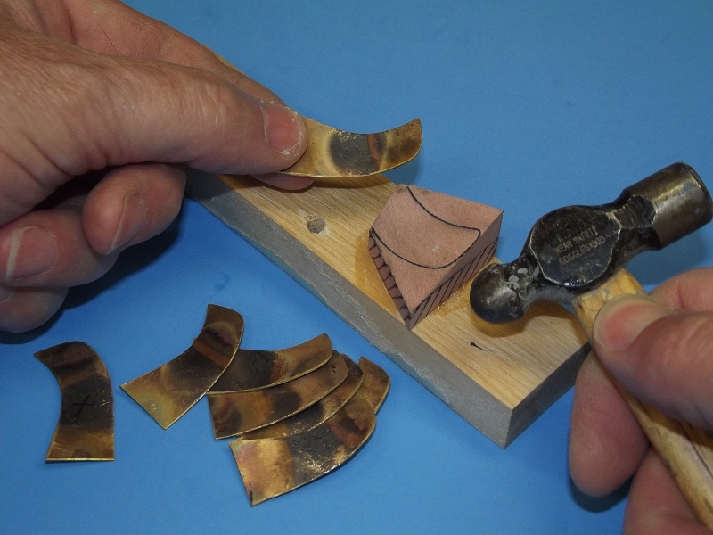
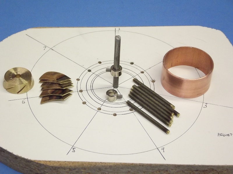
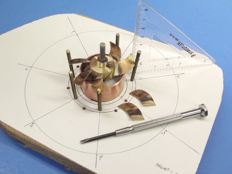
    Once this is turned up to the right diameter then making the brass Blades is the next step. These have also been cut out of brass and given a twist with lemon.. Like BWI I have made a jog to hold the blades in place whilst soldering them. I have learnt through experience that without one you are trying to solder one blade in and the heat goes to the other side and the opposite one that you spent all that time getting right, literally drops out... You have to have some kind of jig for this job...

    more later....

    Dave H

    Leave a comment:


  • He Who Shall Not Be Named
    replied
    Will you PLEASE learn how to scribe a straight line, and do so at a consistent depth!. Your scribing is TERRIBLE. You need to hear this. You need to know more on how to do this, just say so and I'll spoon-feed you till you can do it.

    You're prolific; you build fast; you do good tooling; you produce reasonable GRP and resin parts. Your scribing SUCKS.

    M
    Last edited by He Who Shall Not Be Named; 01-22-2016, 09:22 PM.

    Leave a comment:


  • trout
    replied
    Looks amazing in the water! You have created a wonderful sub!

    Leave a comment:


  • HardRock
    replied
    Looks great Dave. You're going to have to bit the bullet though and PAINT those masts!

    Leave a comment:


  • greenman407
    replied
    Fantastic Job Sir! Anyone who can build a sub from scratch, has got more than the normal amount of scruples if you ask me. LOOKING FORWARD TO SEEING IT UNDER POWER

    Leave a comment:


  • Davidh
    replied
    Hello anybody out there..

    I took the boat down to the local duck pond. Wet humid sticky day. Still without a prop shaft. (that has since arrived) No ducks, plenty of water from last weeks deluge. Good opportunity to look at the trimming, and take some photos of how she looks in the water. I had put some foam and ballast lead in along the lines of how It usually is positioned according to the experience I have with these boats. Big chunk of foam in the front and squeeze as much in the back at I can.

    Initially when she first went in the water she was stern heavy. Took it out and shifted weight up front then squeezed even more foam in the stern. Lower cubic area in the stern means less buoyancy anyway. I think she looks quite nice in the water and I can't wait to see her under power. The photos of her from the 7 o'clock position look like some of the main photos taken of the real boat.


    Hopefully the next pic's will be of her underway and underwater. As mentioned earlier I have a kit in production if there's interest. I'm also trying to get a website up and running.


    Any comments appreciated.

    David h
    Click image for larger version

Name:	Mike (20)03.jpg
Views:	146
Size:	73.4 KB
ID:	112307 Click image for larger version

Name:	overhead view mike.jpg
Views:	130
Size:	25.5 KB
ID:	112315 Click image for larger version

Name:	Mike (21)04.jpg
Views:	179
Size:	66.0 KB
ID:	112308 Click image for larger version

Name:	Mike (22)05.jpg
Views:	154
Size:	76.7 KB
ID:	112309 Click image for larger version

Name:	Mike (23)06.jpg
Views:	124
Size:	58.5 KB
ID:	112310 Click image for larger version

Name:	Mike (24)07.jpg
Views:	142
Size:	70.2 KB
ID:	112311 Click image for larger version

Name:	Mike (26)09.jpg
Views:	154
Size:	74.8 KB
ID:	112312 Click image for larger version

Name:	Mike (25)08.jpg
Views:	125
Size:	54.9 KB
ID:	112313 Click image for larger version

Name:	Mike (27)02.jpg
Views:	152
Size:	55.3 KB
ID:	112314

    Leave a comment:


  • Davidh
    replied
    Hello all,

    Still waiting on the propeller shaft. Holidays virtually over, back to work tomorrow. After this the next posts should show the boat in the water. The most recent work has pretty much been internal. Although waiting for the shaft I have added two hooks, either side of the inner hull for the rubber bands to hold the subdriver in place so it doesn't try to float loose inside the hull. Even though the hull is pretty confined.
    The bands pull around the front side of the valve at the top and so create a pushing force rearward that will push the subdriver hard up against the brass bracket at the back that keeps the module where it needs to be and pushing up against the pro shaft, when I finally get it. I intend on producing my own prop shafts but once again am awaiting parts from O.S for my lathe.

    I've also added some floatation foam in the areas that it's usually needed, even though the boat hasn't hit the water yet. Plenty up the front in the bow where it's needed and some on either side of the pushrods at the back, keeping space for the fore planes which haven't gone in yet. Once again need part for my lathe so I can turn up brass parts (Arbor for keyless tailstock chuck). Once the fore planes are in there will be more room for more foam.

    I have also attached the little vortex attenuators of dissipators or whatever they are, tiny little things just made from tiny oval shaped profiles cut from aluminium and painted black.
    Pretty happy with the paint scheme as mentioned. I always find that the scum line seems to be particulary noticeable when in the water. I guess I'll find out soon.

    Next photos should be boat in the water. Probably still without a shaft and undergoing trimming sessions.

    David H
    Click image for larger version

Name:	_DSC4831.JPG
Views:	108
Size:	46.3 KB
ID:	112216 Click image for larger version

Name:	_DSC4830.JPG
Views:	104
Size:	64.1 KB
ID:	112217 Click image for larger version

Name:	Mike (16)03.jpg
Views:	104
Size:	53.7 KB
ID:	112218 Click image for larger version

Name:	Mike (17)04.jpg
Views:	109
Size:	70.1 KB
ID:	112219 Click image for larger version

Name:	Mike (18)05.jpg
Views:	105
Size:	72.1 KB
ID:	112220 Click image for larger version

Name:	Mike (19)02.jpg
Views:	109
Size:	81.4 KB
ID:	112221


    Leave a comment:


  • Davidh
    replied
    Hello trout,

    The two can method is above the waterline. It is the main upper hull. To achieve the algae build up under the waterline I simply taped off the upper hull and held a white paint can a meter or so back and made quick passes.

    Dave

    Leave a comment:


  • trout
    replied
    Very nice look. The mottled look below the surface came out well, is that where you did the black and grey mix? You can be the weathering master as well!

    Leave a comment:

Working...