Welcome to our forums. For the best in R/C submarine kits, components and accessories, be sure to visit the Nautilus Drydocks
If this is your first visit, be sure to
check out the FAQ by clicking the
link above. You may have to register
before you can post: click the register link above to proceed. To start viewing messages,
select the forum that you want to visit from the selection below.
As per Matt Thor the correct orientation is: The tab on the servo and battery connectors need to be in the UP position. Which makes it White up, Red in the center, black on bottom.
The two pictures in the original post are different. Like the first pictures shows the battery and/or servo's cable from the top to bottom, White-Red-Black with the tab on top. The second picture is NOT correct.
OK, the orientation, as you pictured, here is the polarity and channel assignments for the SubTech Subcommander-6 receiver:
Negative, at the bottom.
Ch-1, facing us, and in sequence away from us, ch-2 through ch-6. Last port (farthest away) is for input power, but I'll bet it services another proportional channel if your transmitter has seven or more channels it can squirt out.
As a practical matter, you can get your 5-volts to the receiver bus through any of the channel ports � if your ESC has a BEC then system operating voltage will be supplied through the negative and hot wires of the ESC�s lead (typically, ch-3). If you expect a peak load over 2-amp�s through the receiver bus (current hungry devices like servos), then provide bus power from a dedicated BEC rated at no less than 5-amp�s.
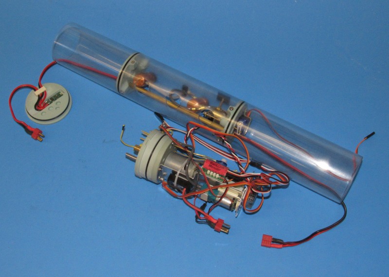
What you see here is a 1/96 THRESHER/PERMIT test-shot. I assembled this GRP, resin and metal kit from the tooling I developed for a customer (this particular one will be his play-toy).
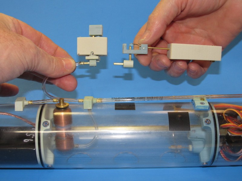
The 2.5� diameter SubDriver (SD) electronics are tightly packed and called for the reduction of the receivers foot-print, that done by getting rid of the provided plastic case and substituting heat-shrink tube to keep from shorting out the bare solder connections on the bottom of the receivers PCB.
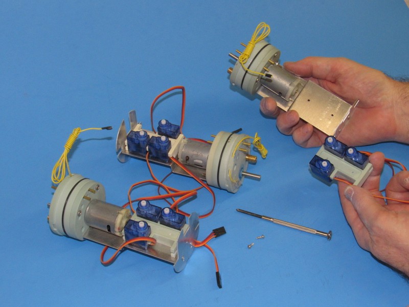
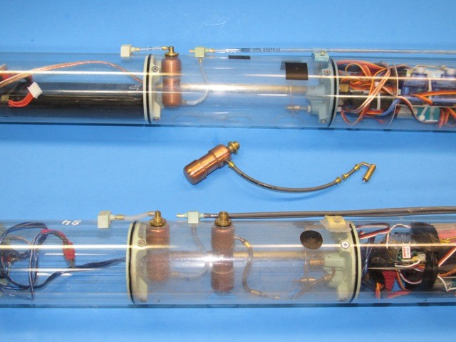
Room in this WTC is at a premium and such measures are called for if things are going to fit (with the aid of hammer and shoe-horn sometimes). In this poorly composed shot you can just make out a receiver that has the heat shrink, next to another in its original plastic case.
In hand: one receiver with the original case, and one in heat-shrink. If you look carefully into the clear Lexan cylinder of the SD you can make out one of these receivers, sandwiched between the servos.
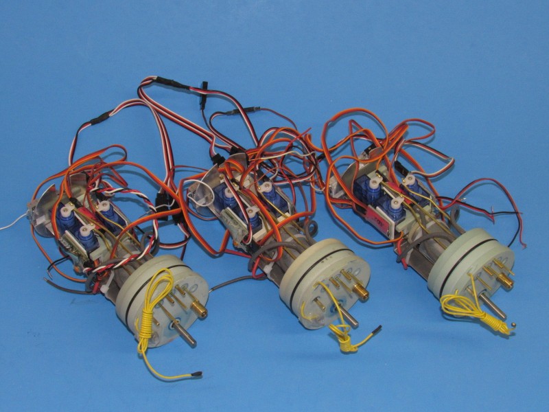
The SubTech Subcommander-6 is a good product, and is well priced. I have three of these gizmos in boats of mine, and another two in the bin for later use.
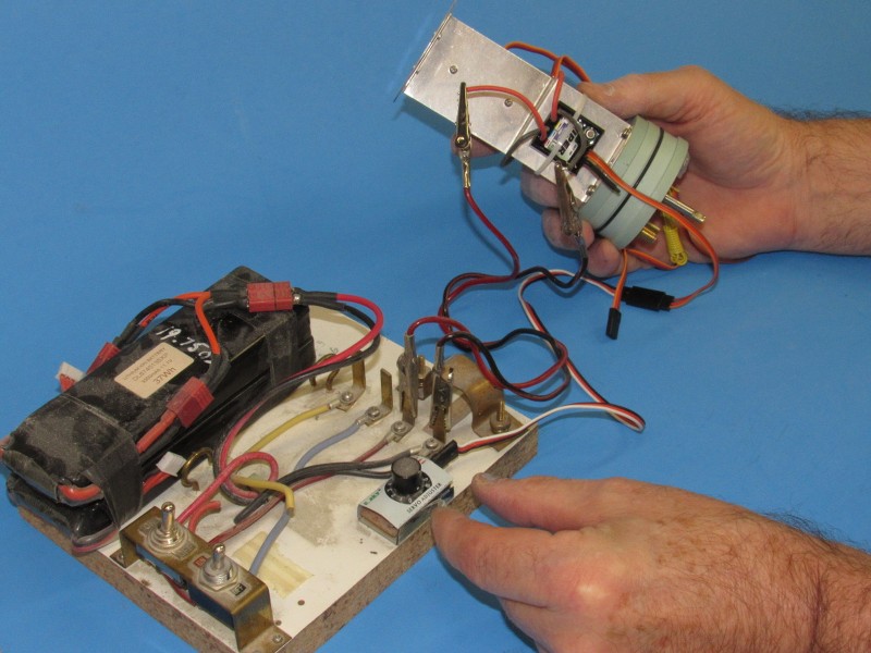
Caution: With the lead pins exposed like this you need to take care not to short across them when powered up or you�ll let out the magic smoke, and you�ll have to spring for a new receiver!
� Guess how I learned that?
It�s a good practice to mark lead polarity and channel number onto the clear heat-shrink over each male connector (these make up to the servo and other device leads).
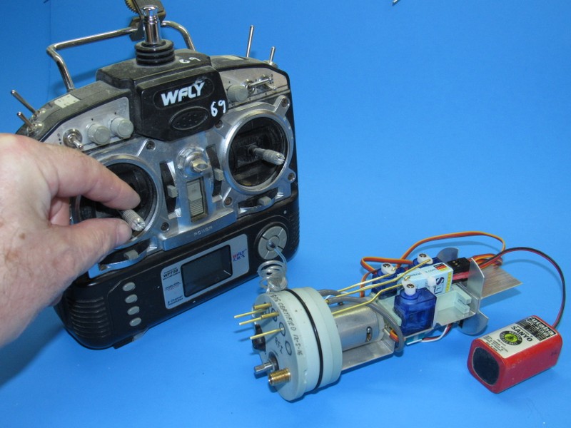
I�ve fallen in love with the (new to us in the r/c submarining community) NEX, six-channel transmitter. These are marketed through the Nautilus Drydocks. Here�s the page for that thing:
(OK, I�m a whore � I work for the Nautilus Drydocks. So, there!)
What makes this six channel transmitter unique is the assignment of ch-5 and ch-6 to push-button controls � sure, not proportional, but perfect for my kind of r/c submarine driving. Channel-5 for stern planes up/down, and channel-6 for ballast blow/vent. Not to worry: when no button is pushed, the on-board angle-keeper tends the planes to keep the boat on or about a zero bubble-angle.
I�m just about the best submarine driver in the US. Fact. Deal with it. (Keeping in mind that we US r/c submarine drivers are rank amateurs when compared to our European counter-parts). I require positive, quick response to transmitted commands. Particularly the stern planes.
At times I like to race around. Not just fast (any idiot can go fast), but fast and under full control, without running into things. An aid to this control is the ability to control depth-angle through �quick-blipping� of the stern planes, i.e. immediate and large deflection of the control surfaces through two undemanding, immediate response push-buttons.
And that�s what�s on the back-side of the VEX transmitter: One button for full �rise�, the other button on that channel for full �dive�; a simple bang-bang actuation. When no stern plane button is pushed, the angle-keeper is in charge of the boats angle.
But, the signal that these back-side buttons put to the transmitters encoder could just as easily have originated from a potentiometer for proportional response of the on-board servo � which you can do by modifying the transmitter with a slide-switch pot instead of the buttons.
The default servo response to a pushed button is 100% travel. However, as this transmitter is a �computer� type, you have the option of setting the end-points servo travel anywhere between 0% and 120% deflection.
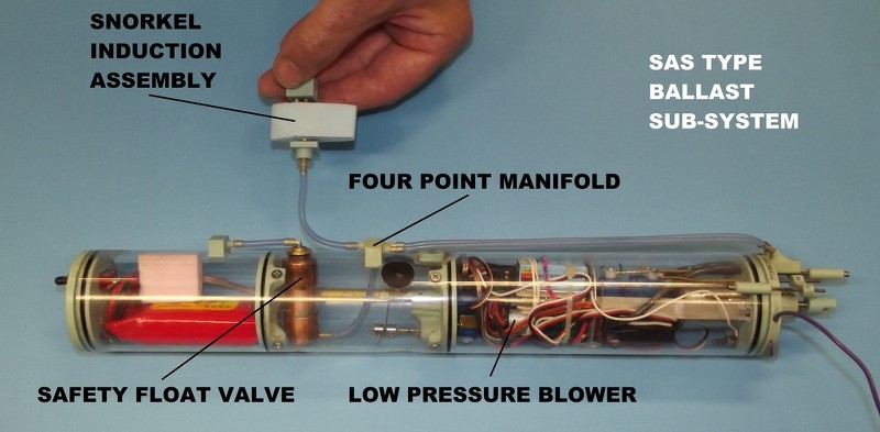
The other set of push buttons is for the ballast system: one button to vent, the other button to blow (I use the SAS ballast sub-system, but this will work with just about any other model of ballast water management).
David,
Do you have a picture of the underside of this 2.5" WTC? I would like to see your configuration of the ESC, Air pump (LPB), and the Angle Driver (angle-keeper). I have the AD2, LPB, and ESC to be installed on the underside of the aluminum plate for my latest Blueback reconfiguration.
David,
Do you have a picture of the underside of this 2.5" WTC? I would like to see your configuration of the ESC, Air pump (LPB), and the Angle Driver (angle-keeper). I have the AD2, LPB, and ESC to be installed on the underside of the aluminum plate for my latest Blueback reconfiguration.
Thanks
Ernie
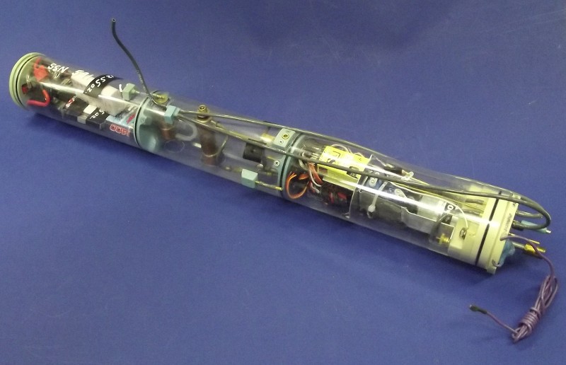
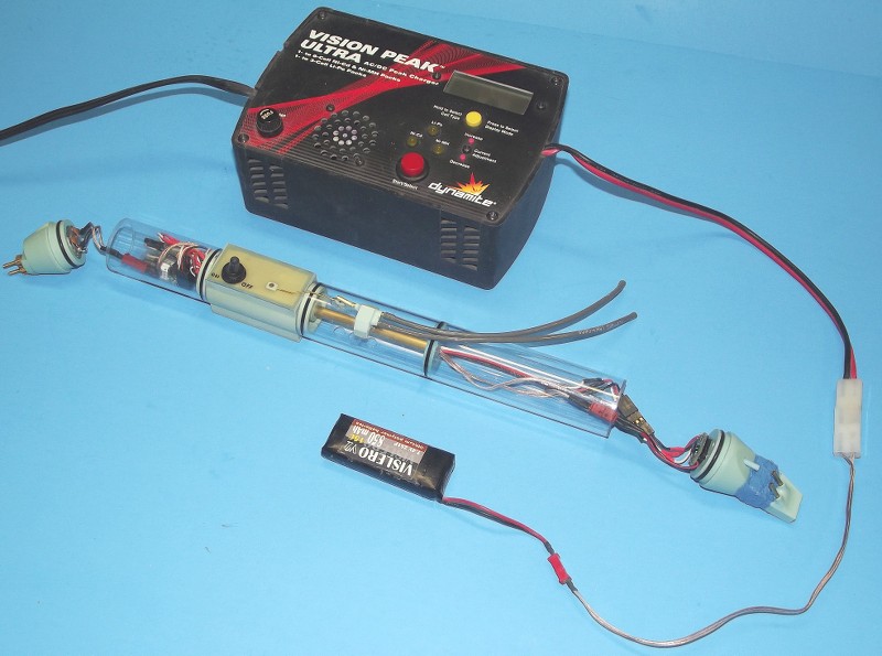
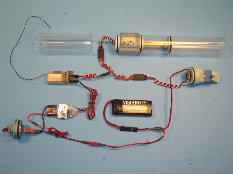
Don't have any more shots of this particular set-up, but the following will give some ideas as to device location and interface:

 Tweet
Tweet


 [/URL
[/URL


Comment