Hello! I have recently purchased the Type 9 starter kit from the Nautilus Drydocks website and I am having problems setting up the sub driver for it. I have watched Bob's video about the Type 7's SD and his SD is very similar to mine but his servos, receiver, and ESC already came pre-installed. Can anyone give me a step-by-step of setting up this thing and/or answer some other questions I have about the model?
Type 9 sub driver from Nautilus Drydocks: how to setup?
Collapse
X
-
-
Comment
-
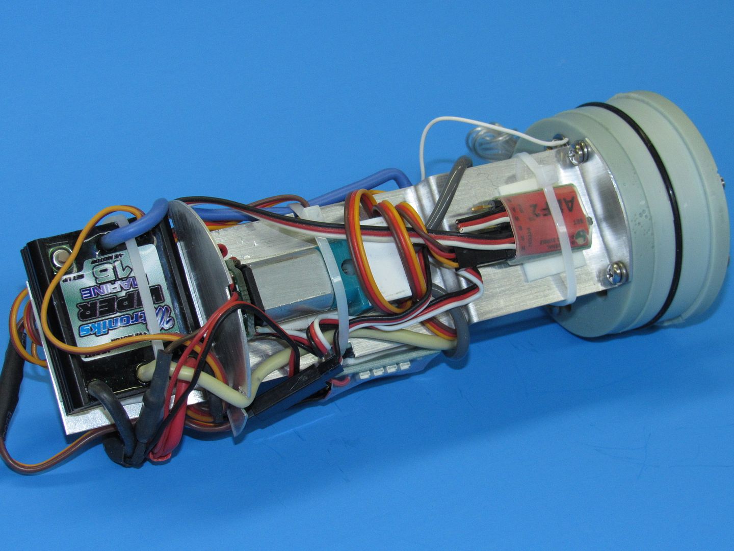
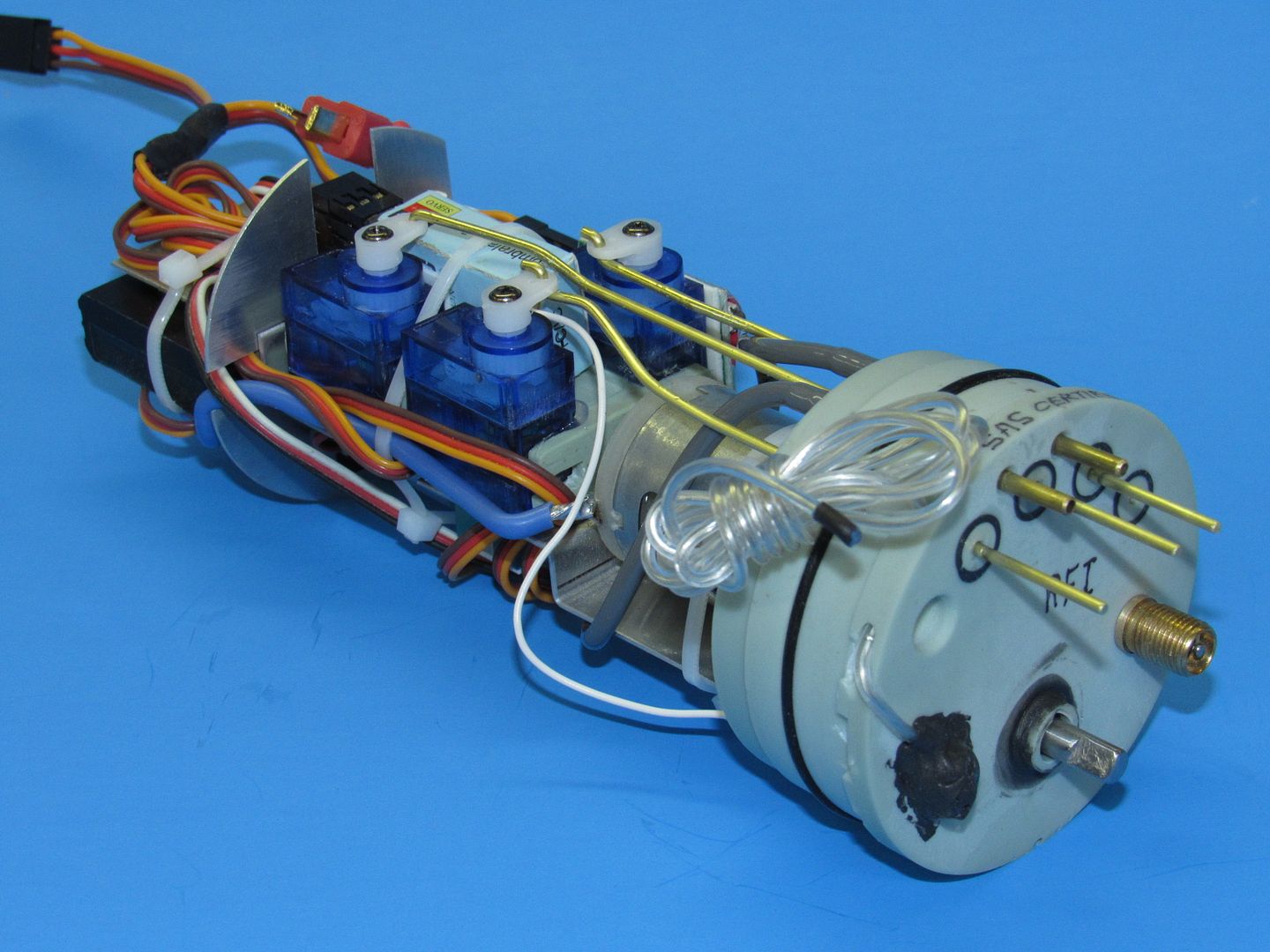
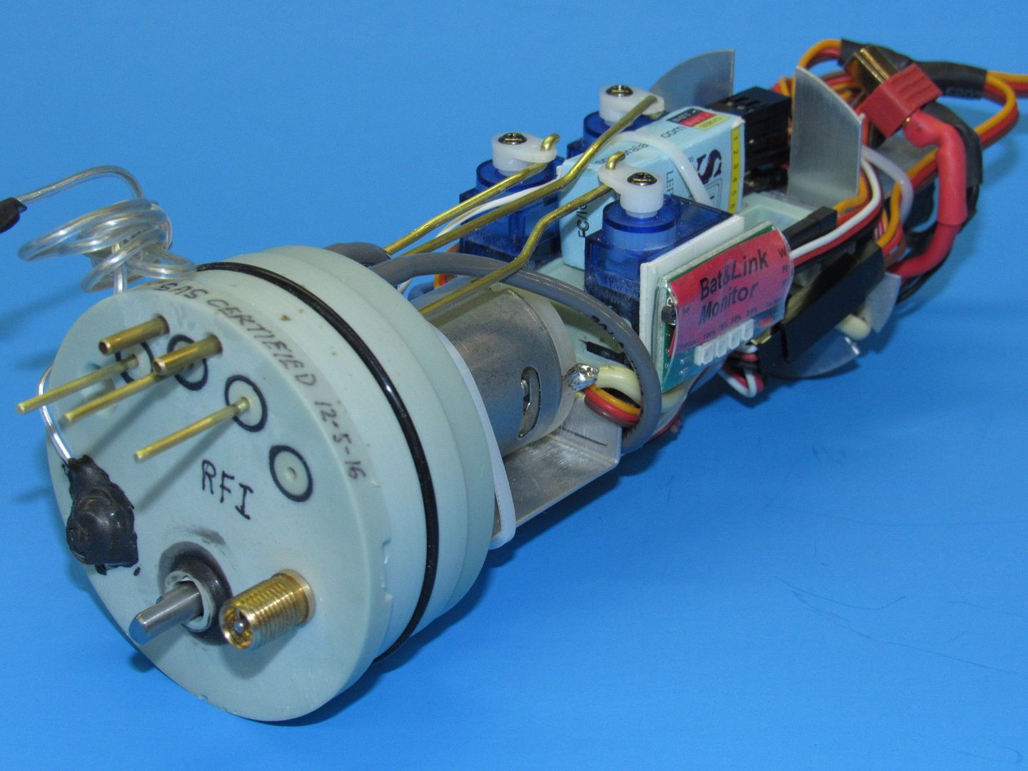
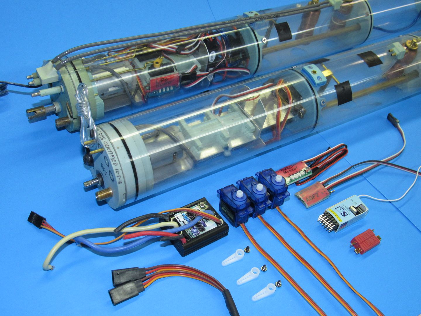
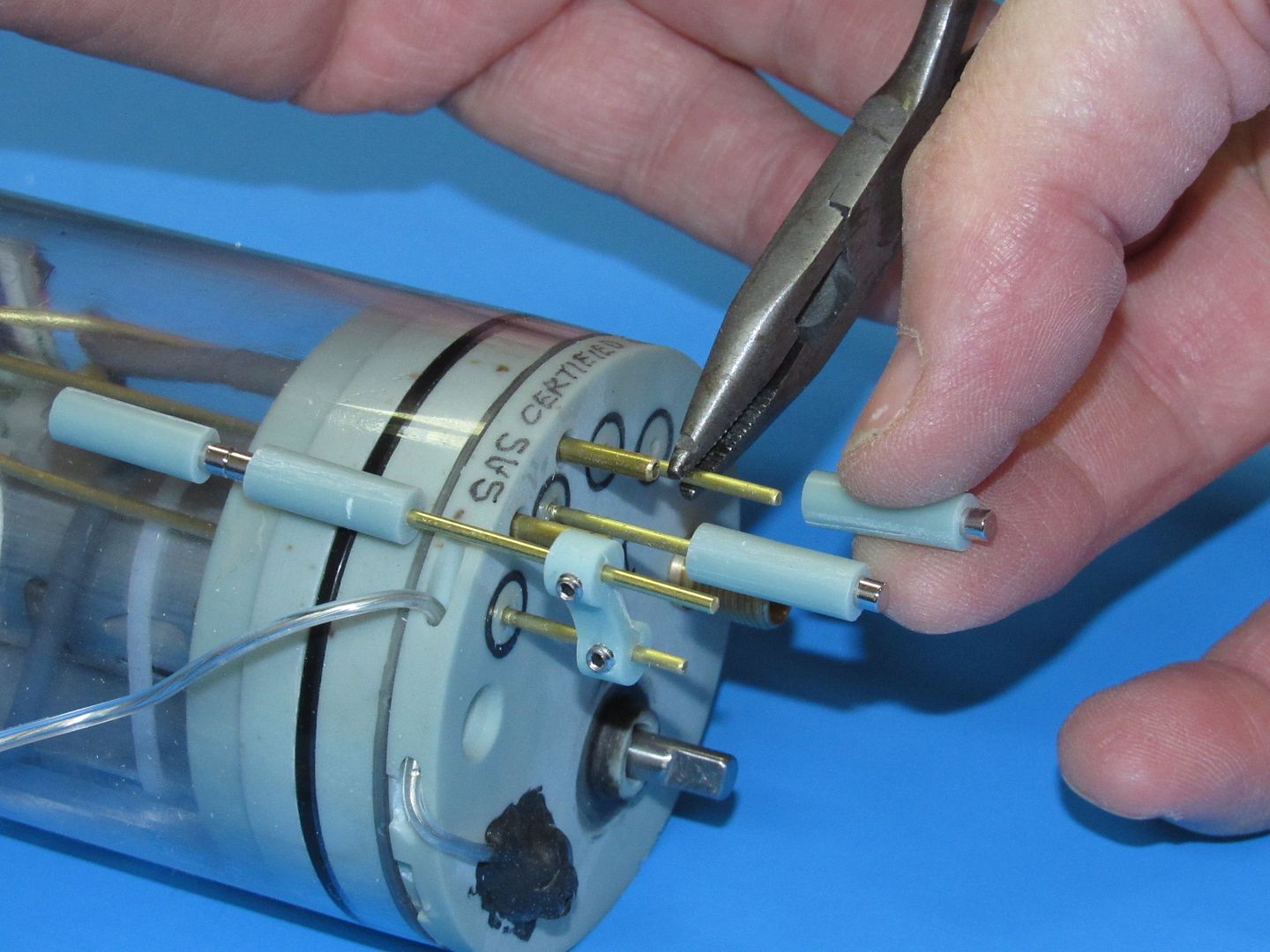
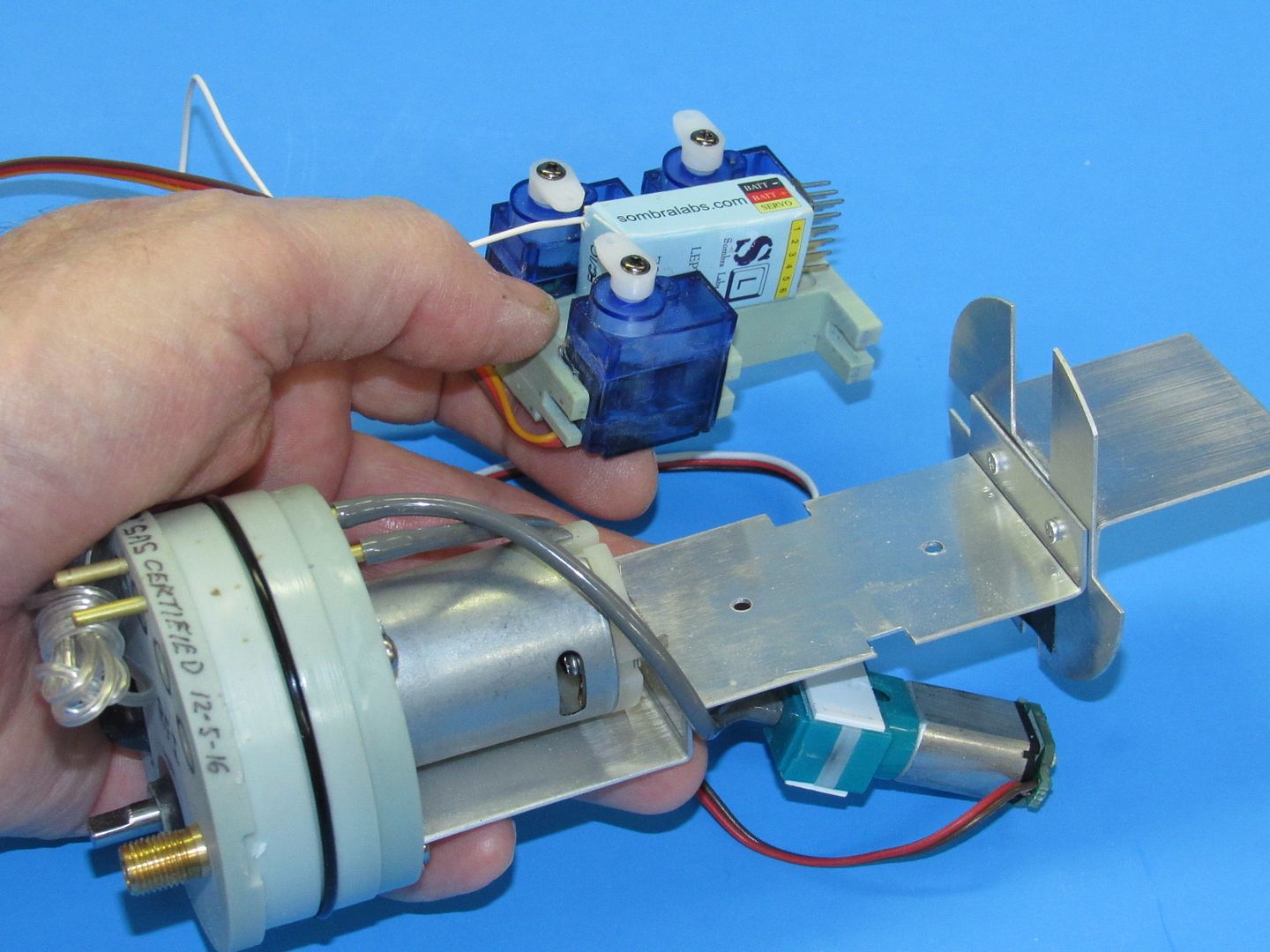
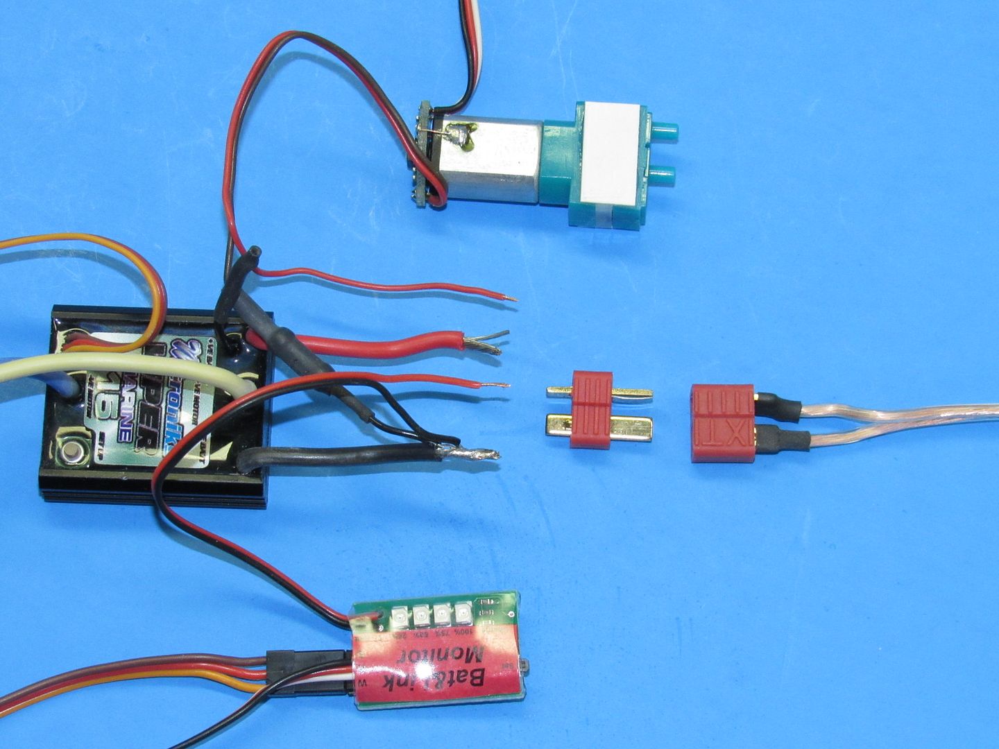
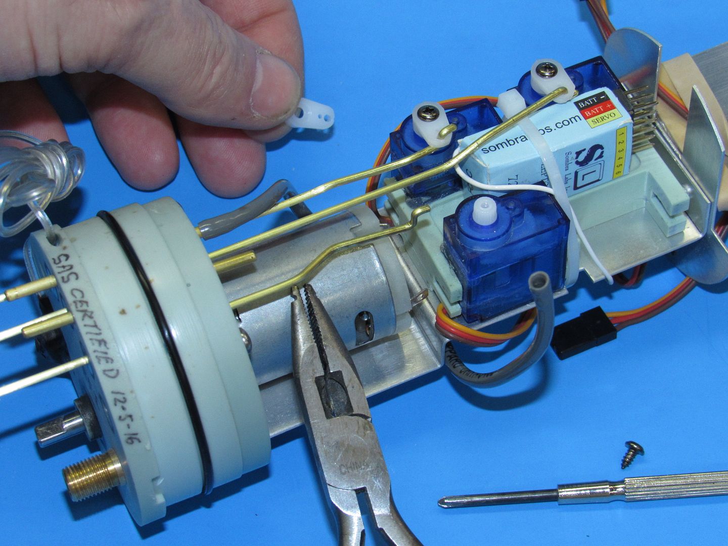
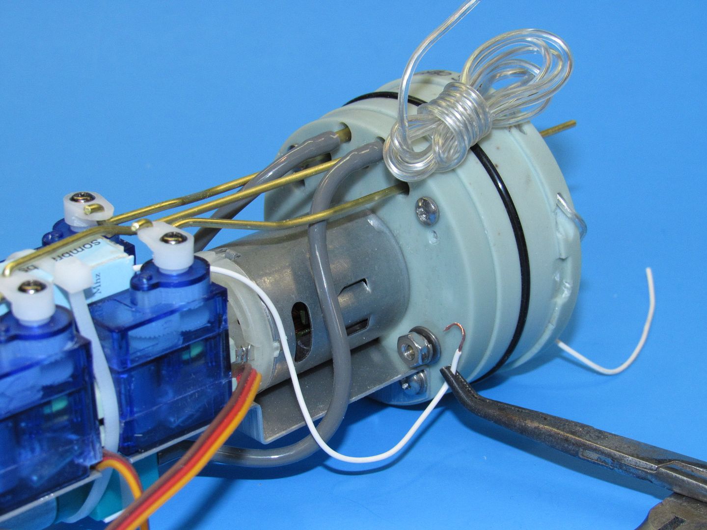
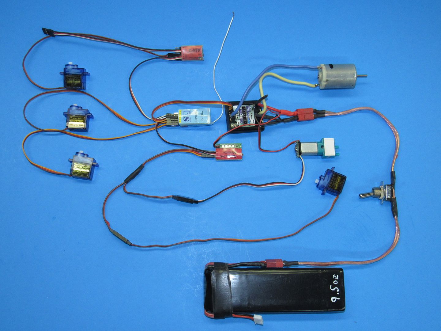
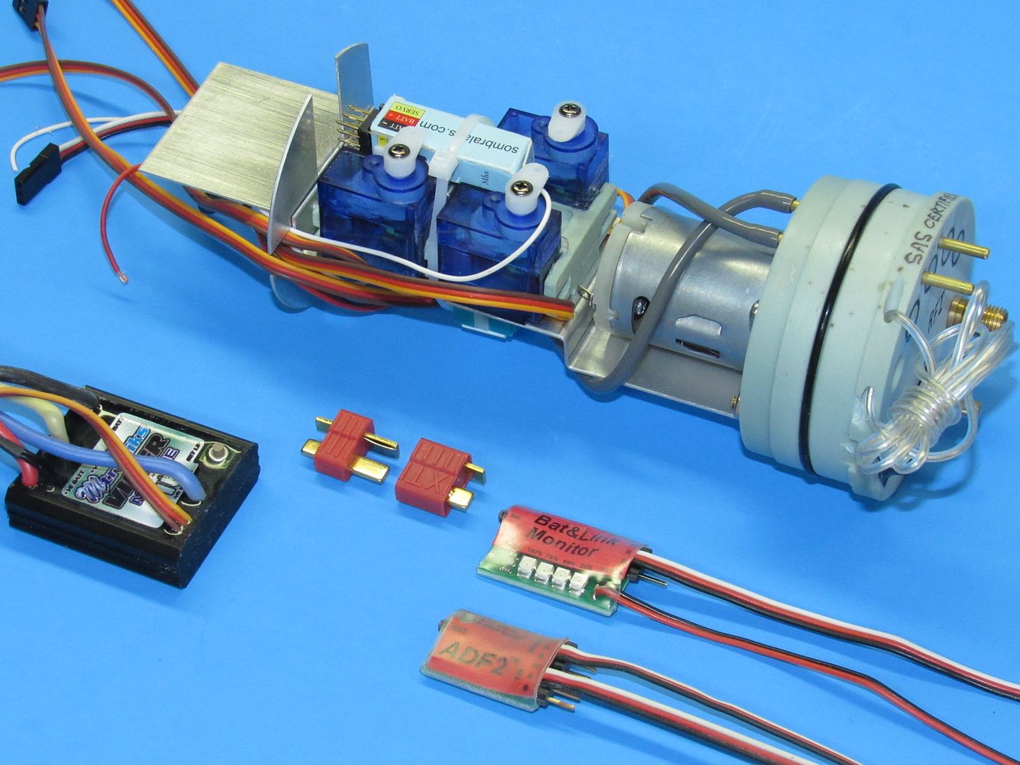
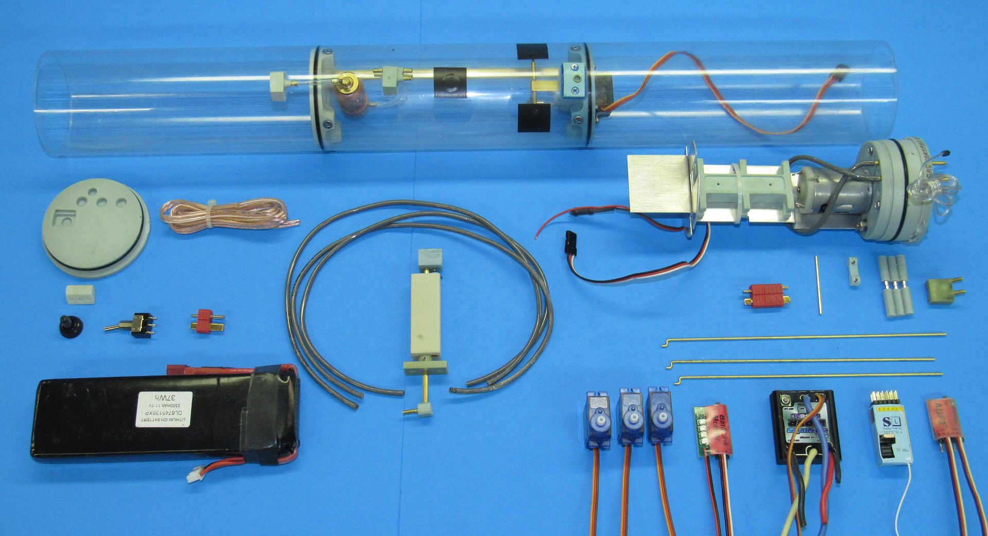
Above is how you populate the 2.5 SD with the devices as well as how to run the power cables through the mission switch. Examine these shots, formulate your specific questions and I'll talk you down to a safe landing.
David[/QUOTE]
Wow! These really help. Thanks!
So I don't have a battery link monitor so I assume I just Y-cable the servo and the pump strait to the receiver yea? Also it seems I'll have to go to the hobby shop to get some copper wire, or is that what the blue cable in a zip-tie is for? I'll have to go anyways to get some heat shrink and a few Deans adapters. I'll try to get as far as I can but for now those two are the only questions I have. Again, thank you.
Edit: I have this HUGE receiver that came with the kit, it's the Futaba FP-R127DF. Also I assume that's a low frequency receiver right? I've heard you can't use higher frequencies underwater.Last edited by warLOCK; 06-27-2017, 05:44 PM.Comment
-
Another question: did you cut off the switch on the ESC, solder the two wires together, and then put heat shrink over it? That would make sense, because it would always be in an on state as long as the battery was plugged in, which is what you want, but I'm just making sure.Comment
-
Wow! These really help. Thanks!
So I don't have a battery link monitor so I assume I just Y-cable the servo and the pump strait to the receiver yea? Also it seems I'll have to go to the hobby shop to get some copper wire, or is that what the blue cable in a zip-tie is for? I'll have to go anyways to get some heat shrink and a few Deans adapters. I'll try to get as far as I can but for now those two are the only questions I have. Again, thank you.
Edit: I have this HUGE receiver that came with the kit, it's the Futaba FP-R127DF. Also I assume that's a low frequency receiver right? I've heard you can't use higher frequencies underwater.[/QUOTE]
Sure, put the Y-connected ballast servo and pump controller straight to the receivers ch-4. But, unless your receiver has a fail-safe function of its own, you won't protect the system against a loss-of-signal. No fail-safe protection (unless you operate in a pool) is dumb!
Yeah, that's a big-ass receiver (75mHz is fine for our use). Take it out of the case and heat-shrink the unit to keep from shorting out the board as you handle and install it. No sweat.
Like this (these are 2.4gHz, but that's not the issue here -- just showing how to heat-shrink protect the board):
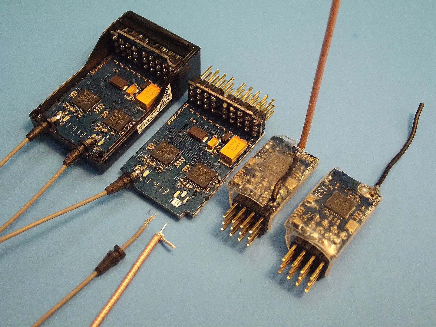
That blue wire is one of the two output leads between the ESC and motor.
DavidWho is John Galt?Comment
-
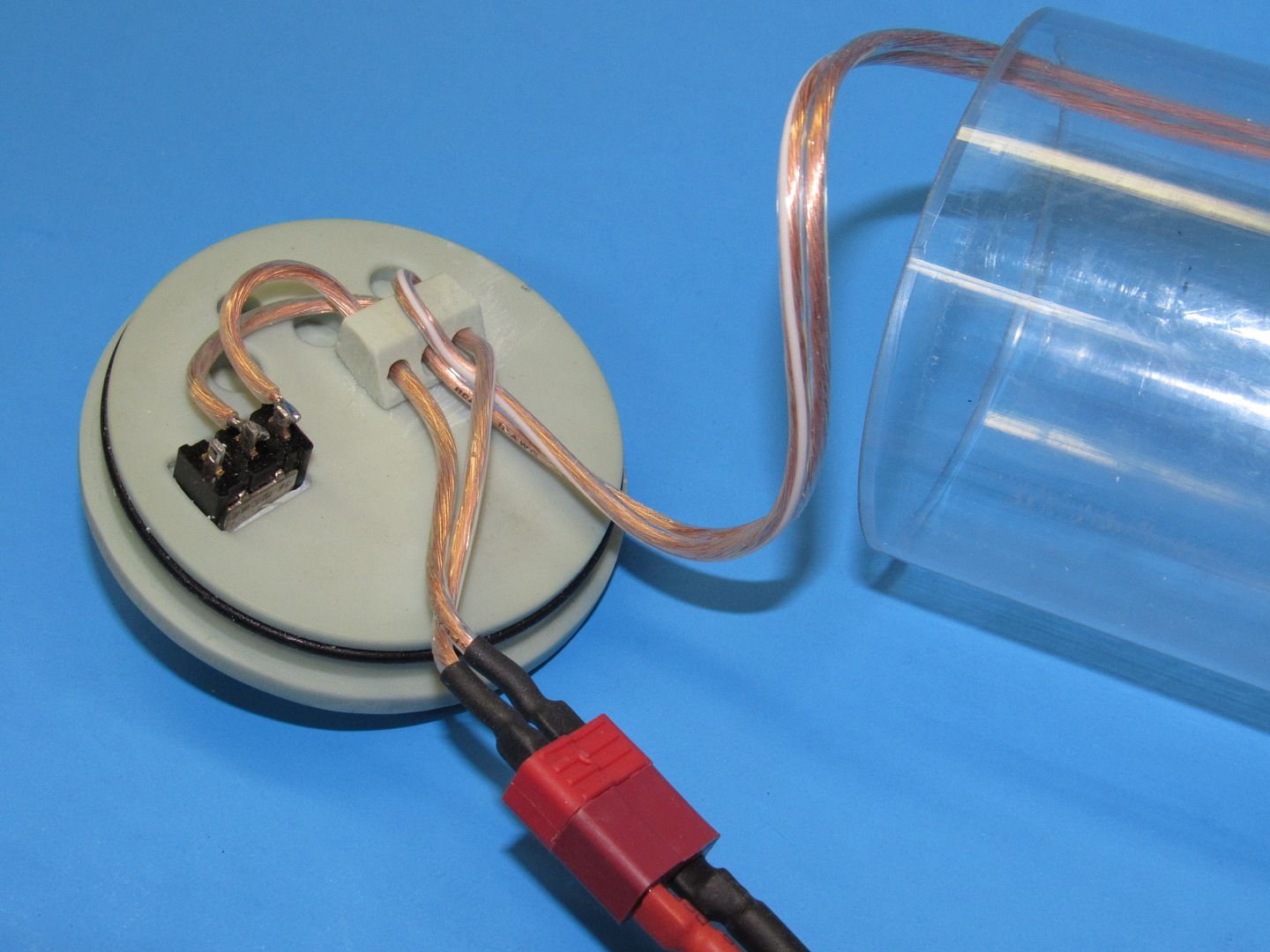
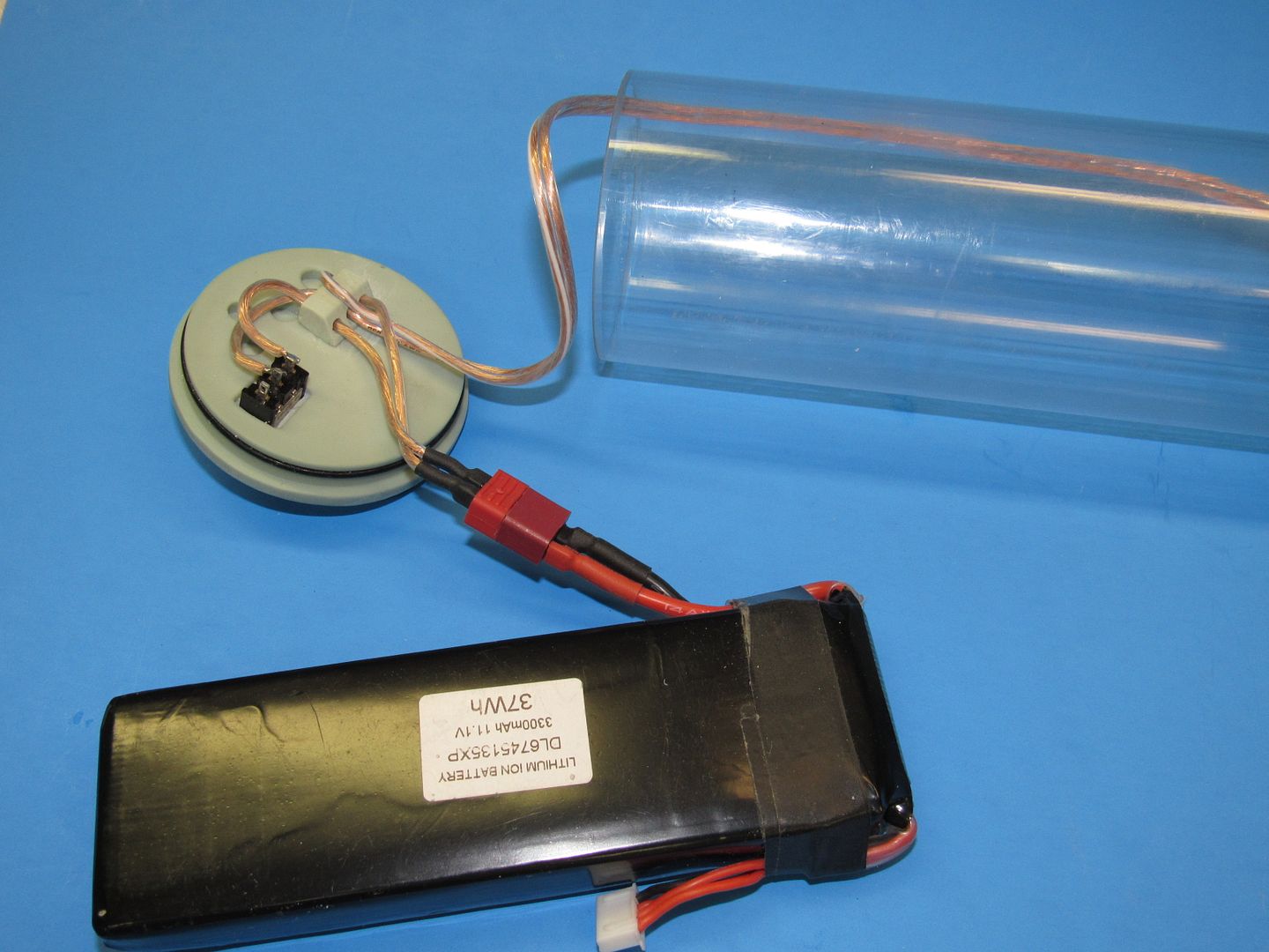
The blue wire I was talking about seems to be the battery connector that goes through the brass tube. Yours is some sort of yellow-ish color, hence the confusion. But I have everything set up here and it all seems to work, except that blue wire which I've isolated as the problem. I've already gotten it through the tube but when I plug the battery in, the electronics section doesn't get any power. I don't really know why this is happening, because everything works then I plug it directly into the electronics section. Do I have it in right? The wire with the white strip in it is positive, and the regular wire is negative right?Comment
-
Do you have a multimeter to check continuity? It sounds like faulty solder or is there a chance there is a bare spot shorting against the brass tube?
If you can cut, drill, saw, hit things and swear a lot, you're well on the way to building a working model sub.Comment

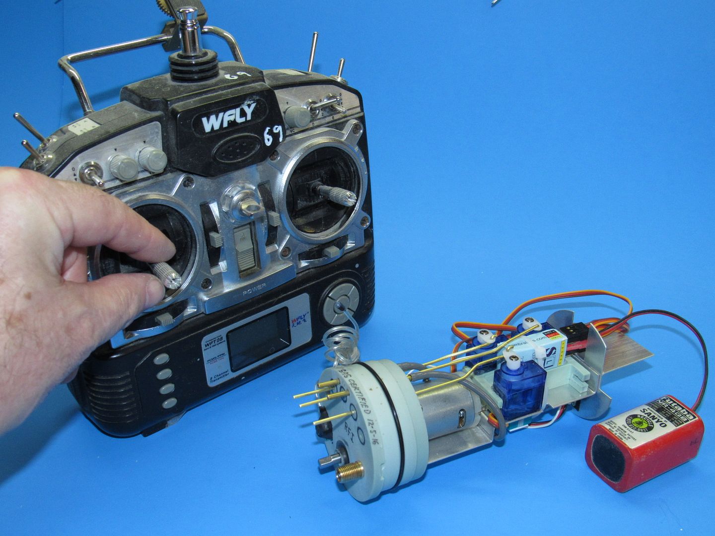
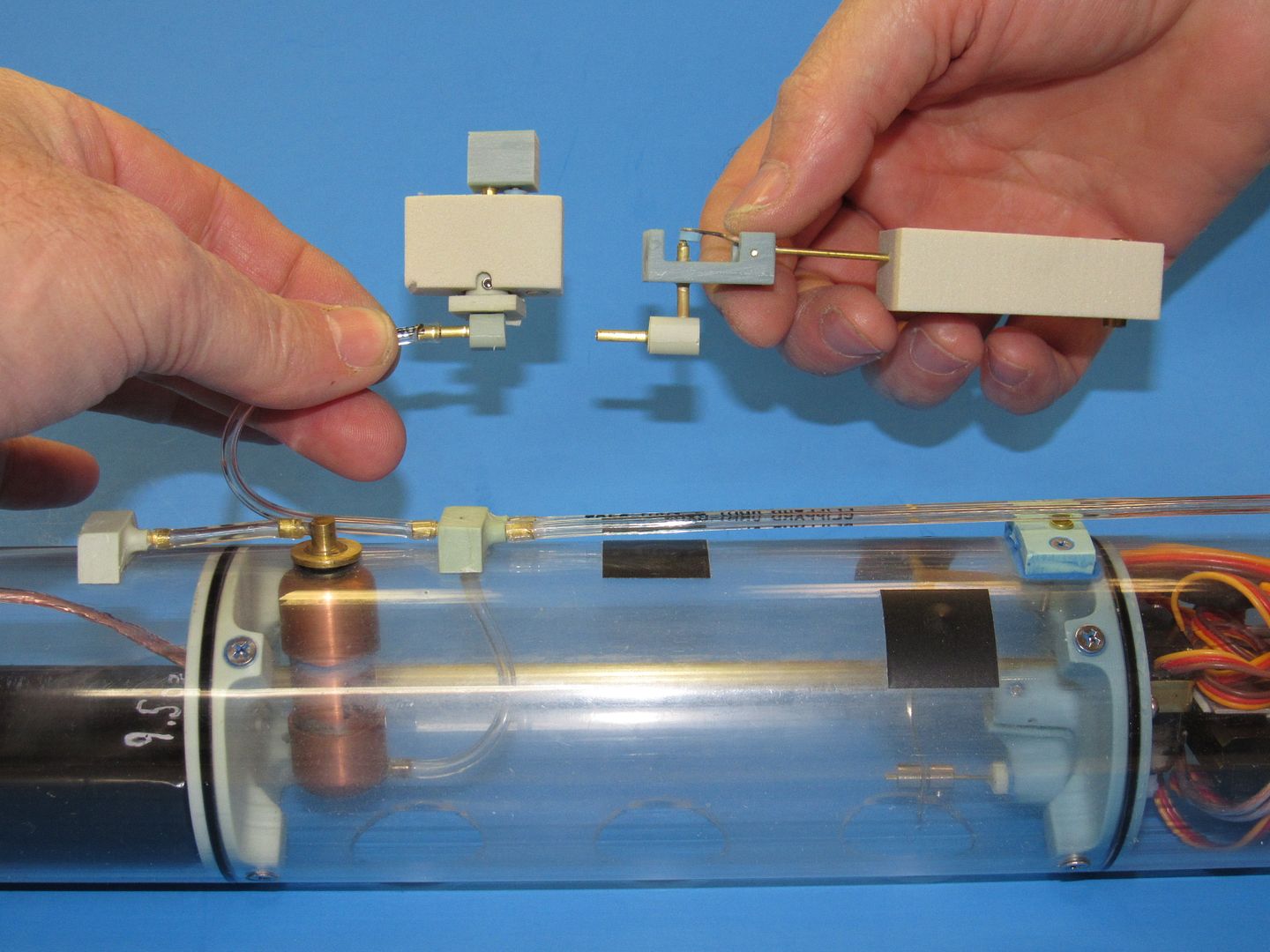
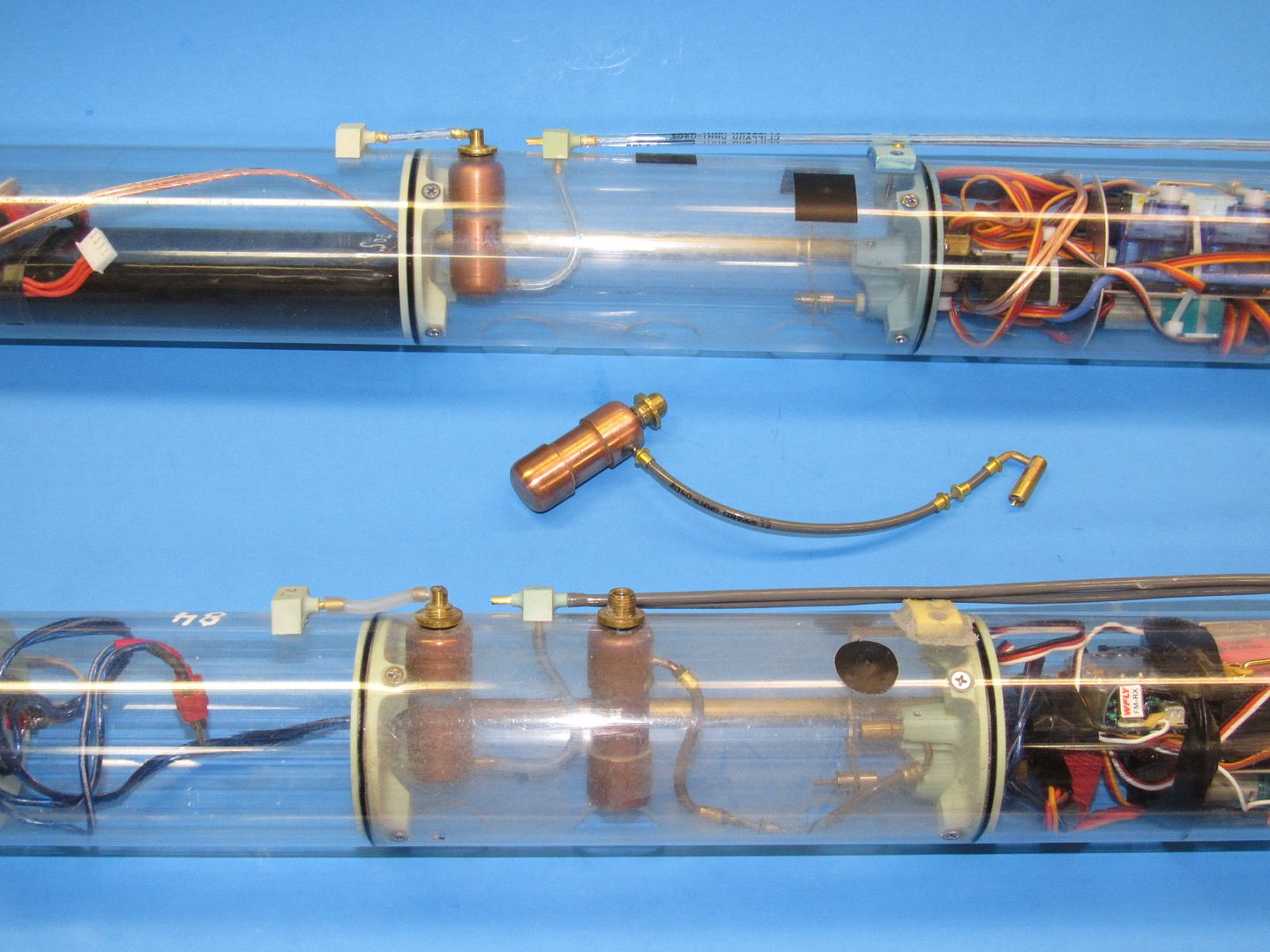

Comment