
 Tweet
Tweet
A LITTLE PREAMBLE
Up to the beginning of the twentieth century the accepted method of joining together ship hull plating was through the use of rivet type mechanical fasteners. In the beginning these rivets had a head and heal that stood proud of the hulls exterior and interior. The flush fitting rivets -- where the V-shaped head of the rivet compressed into the chamfered hole of the plate -- came into vogue, in some applications, during the later nineteenth century
.
This discussion will be focused on the three most common rivet types we would see on a ship or submarine built in the, 'age of sail'.
Before the almost universal practice of welding had replaced the rivet as the principle means of affixing metal hull plates together, rivets were the preferred method of bonding metal-to-metal. And, as you would guess, there were many different head styles of rivet, as well as patterns to which the rivets were laid down.
Presented here are model representations of the round, flat, and counter-sunk type rivets. The subjects are a r/c 1/16 USS ALLIGATOR; an r/c 1/12 HUNLEY Confederate privateer; and a smaller static display 1/24 HUNLEY.
Before launching into the discussion proper, I want to inform the reader that both HUNLEY models used as examples here were commissioned and built long before the HUNLEY revelations -- after examination of the salvaged original submarine off the coast of Charleston.
it's interesting to note that the Confederate And Union submarines of the Civil War were both constructed of metal butt-joined (carvel plating) metal plate held tightly together by counter-sunk rivet s whose round heads were flat and flush with the outer surface of the hull. A streamlining measure only recently appreciated my marine vessel Conservators and historians.
(It was not until the salvage and examination of the actual HUNLEY did we realize the error all the illustrators and model-builders made previous to that revelation: we all assumed round-head rivets sticking high and proud off the submarines hull).
The two HUNLEY models are presented here to demonstrate two different technique for representing round-head type rivets over lap-joined and radial clinker hull plating. These models are poor representations of the actual HUNLEY submarine, but have utility here as very good rivet application training-aids.
THE SUBJECTS CHOSEN TO DEMONSTRATE MY RIVETING TECHNIQUES
[IMG]file:///C:/Users/David/AppData/Local/Temp/msohtmlclip1/01/clip_image002.jpg[/IMG]

This 1/16 scale effects miniature represents the USS ALLIGATOR. America's first commissioned submarine. It commissioned for and appeared on the Discovery Science Channel episode, The Hunt For The Alligator. A fully capable r/c model submarine, this effects miniature featured screw-type propeller propulsion; a gas type ballast sub-system; deployable anchor; practical diver and conning hatches; and practical suspension floats -- used to stabilize the boat about the pitch axis and suspend the submarine at specific depth from the surface through deployment and recovery of the float lines.
[IMG]file:///C:/Users/David/AppData/Local/Temp/msohtmlclip1/01/clip_image004.jpg[/IMG]
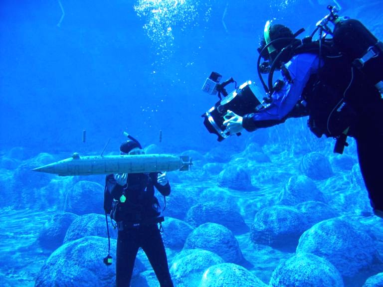
(An interesting aside: While filming the TV show it was found that the deployed stabilization buoys raised the vehicles center of buoyancy so high above its center of gravity that even at a significant advance through the water, the static stability of the boat about the pitch axis was so high as to counter the dynamic forces that would have otherwise (with a closely coupled c.b. and c.g.) made the boat unstable about the pitch axis. The ALLIGATOR had no horizontal control surfaces! No active means of controlling the boats pitch angle. Yet, it was found during our use of the effects miniatures during production, that with the buoys deployed (as seen in this production shot) that I could control the boat easily by slight changes in the amount of ballast water aboard. The deployed buoys keep the submarine on a near zero pitch angle -- deep control was effected by ballast water taken on/pumped out alone!).
[IMG]file:///C:/Users/David/AppData/Local/Temp/msohtmlclip1/01/clip_image006.jpg[/IMG]
[IMG]file:///C:/Users/David/AppData/Local/Temp/msohtmlclip1/01/clip_image008.jpg[/IMG]

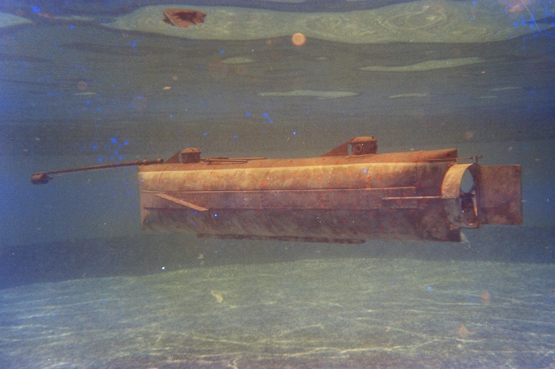
The 1/12 HUNLEY: Though I was not involved in the hull construction of this model, I was dragooned into the project as the initial builders became preoccupied with other work. I took on this model after receiving the basic hull, with little else. Because this model is based on the W.A. Alexander sketches -- a document so highly referenced over the decades as to have become almost canon until recent times -- this model IS NOT a proper representation of what we now know the HUNLEY to be.
If only we had followed the Chapman miniature painting and pencil studies -- which were first-person depictions of the vessel -- we would have been very close to what the Conservators recently found out.
The written and illustrated history bit me on the ass on this one.
However, I did complete the model and r/c'ed it for the customer. And it worked surprisingly well underwater. As long as the speed was kept below a critical limit, the single set of bow planes was enough to effect good depth control. But, above the critical speed the boat would either pitch up or down violently. And that's why the real boat worked so well: being man powered, it could never attain a speed where the static stability of the boat was defeated by hydrodynamic forces created as a consequence of speed, i.e. the boat worked because it was slow. It was man-powered.
[IMG]file:///C:/Users/David/AppData/Local/Temp/msohtmlclip1/01/clip_image010.jpg[/IMG]

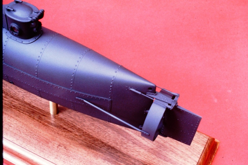
This wooden and cast resin 1/24 static display model was commissioned by a collector. And, like the above r/c HUNLEY was built based on the rather inaccurate drawings based on the sketches of W.A. Alexander
NOW ... THE RIVETS DISCUSSION
COUNTER-SUNK (FLUSH) RIVETS AS ENGRAVED CIRCLES The little known (historian's have been so negligent in regards to this incredible submarine) or appreciated Union ALLIGATOR, a contemporary of the Confederate HUNLEY, likely was built with the same type materials and fasteners as her southern sister. I was commissioned to build model, an effects miniature, representing the arrangement of the ALLAGATOR shortly before its loss while being towed around Cape Hatteras.
A fortunate circumstance: at the time the salvaged HUNLEY was giving up her secrets, I began design and physical work on the miniature -- I endeavored to detail the ALLIGATOR by representing the same type plating joins, fasteners, and manufacturing techniques seen on the HUNLEY.
[IMG]file:///C:/Users/David/AppData/Local/Temp/msohtmlclip1/01/clip_image012.jpg[/IMG]

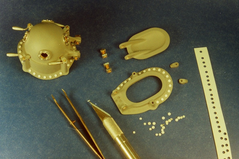
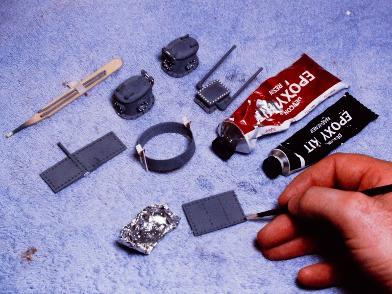
That meant that the hull plating rivets would be represented as circles, each defining the perimeter of the rivet head as it sat in its chamfered hole in the plate. The models hull would have to be engraved with hundreds of little circles. On the other hand, those structures mounted onto the hull would be outfitted with simulated flat type rivets, that sat proud upon the items mounting flange -- those rivets represented by little punched out discs of .010" polystyrene sheet.
[IMG]file:///C:/Users/David/AppData/Local/Temp/msohtmlclip1/01/clip_image014.jpg[/IMG]

[IMG]file:///C:/Users/David/AppData/Local/Temp/msohtmlclip1/01/clip_image016.jpg[/IMG]

The hull proper, a GRP structure with a heavy gel-coat serving as the outer substrate, was first marked off with pencil to denote the butt plate joins.
The productions main art-director and ALLIGATOR expert, Jim Christly, informed me that the hull was likely made from rolled sheet of iron plate that came from the mill in four-foot wide sections. Scaling that to the model gave me the longitudinal distance between engraved radial lines (used to represent the butt-joints between plates).
Scribing scratch-awl and razor saw were used to cut in the radial and longitudinal engraved lines -- I had planned for this when laying up the hull GRP parts -- having taken care to provide a very heavily filled gel-coat before laying down the glass laminates. It's easy to scribe soft gel-coat. It's a complete son-of-***** to engrave across strands of glass! A lesson learned early in my model-building career.
[IMG]file:///C:/Users/David/AppData/Local/Temp/msohtmlclip1/01/clip_image018.jpg[/IMG]

A rotary cutting tool would actually engrave the small circles representing rivet heads. On the mill -- taking advantage of the indexed X-slide hand-wheel, which gave me perfectly uniform spacing -- I drilled guide-holes into annealed brass strips. Those drilled strips becoming indexed drilling jigs used to give uniform spacing and depth as the rotary cutter engraved the little circles into the surface of the hull.
[IMG]file:///C:/Users/David/AppData/Local/Temp/msohtmlclip1/01/clip_image020.jpg[/IMG]

Up to the beginning of the twentieth century the accepted method of joining together ship hull plating was through the use of rivet type mechanical fasteners. In the beginning these rivets had a head and heal that stood proud of the hulls exterior and interior. The flush fitting rivets -- where the V-shaped head of the rivet compressed into the chamfered hole of the plate -- came into vogue, in some applications, during the later nineteenth century
.
This discussion will be focused on the three most common rivet types we would see on a ship or submarine built in the, 'age of sail'.
Before the almost universal practice of welding had replaced the rivet as the principle means of affixing metal hull plates together, rivets were the preferred method of bonding metal-to-metal. And, as you would guess, there were many different head styles of rivet, as well as patterns to which the rivets were laid down.
Presented here are model representations of the round, flat, and counter-sunk type rivets. The subjects are a r/c 1/16 USS ALLIGATOR; an r/c 1/12 HUNLEY Confederate privateer; and a smaller static display 1/24 HUNLEY.
Before launching into the discussion proper, I want to inform the reader that both HUNLEY models used as examples here were commissioned and built long before the HUNLEY revelations -- after examination of the salvaged original submarine off the coast of Charleston.
it's interesting to note that the Confederate And Union submarines of the Civil War were both constructed of metal butt-joined (carvel plating) metal plate held tightly together by counter-sunk rivet s whose round heads were flat and flush with the outer surface of the hull. A streamlining measure only recently appreciated my marine vessel Conservators and historians.
(It was not until the salvage and examination of the actual HUNLEY did we realize the error all the illustrators and model-builders made previous to that revelation: we all assumed round-head rivets sticking high and proud off the submarines hull).
The two HUNLEY models are presented here to demonstrate two different technique for representing round-head type rivets over lap-joined and radial clinker hull plating. These models are poor representations of the actual HUNLEY submarine, but have utility here as very good rivet application training-aids.
THE SUBJECTS CHOSEN TO DEMONSTRATE MY RIVETING TECHNIQUES
[IMG]file:///C:/Users/David/AppData/Local/Temp/msohtmlclip1/01/clip_image002.jpg[/IMG]
This 1/16 scale effects miniature represents the USS ALLIGATOR. America's first commissioned submarine. It commissioned for and appeared on the Discovery Science Channel episode, The Hunt For The Alligator. A fully capable r/c model submarine, this effects miniature featured screw-type propeller propulsion; a gas type ballast sub-system; deployable anchor; practical diver and conning hatches; and practical suspension floats -- used to stabilize the boat about the pitch axis and suspend the submarine at specific depth from the surface through deployment and recovery of the float lines.
[IMG]file:///C:/Users/David/AppData/Local/Temp/msohtmlclip1/01/clip_image004.jpg[/IMG]
(An interesting aside: While filming the TV show it was found that the deployed stabilization buoys raised the vehicles center of buoyancy so high above its center of gravity that even at a significant advance through the water, the static stability of the boat about the pitch axis was so high as to counter the dynamic forces that would have otherwise (with a closely coupled c.b. and c.g.) made the boat unstable about the pitch axis. The ALLIGATOR had no horizontal control surfaces! No active means of controlling the boats pitch angle. Yet, it was found during our use of the effects miniatures during production, that with the buoys deployed (as seen in this production shot) that I could control the boat easily by slight changes in the amount of ballast water aboard. The deployed buoys keep the submarine on a near zero pitch angle -- deep control was effected by ballast water taken on/pumped out alone!).
[IMG]file:///C:/Users/David/AppData/Local/Temp/msohtmlclip1/01/clip_image006.jpg[/IMG]
[IMG]file:///C:/Users/David/AppData/Local/Temp/msohtmlclip1/01/clip_image008.jpg[/IMG]
The 1/12 HUNLEY: Though I was not involved in the hull construction of this model, I was dragooned into the project as the initial builders became preoccupied with other work. I took on this model after receiving the basic hull, with little else. Because this model is based on the W.A. Alexander sketches -- a document so highly referenced over the decades as to have become almost canon until recent times -- this model IS NOT a proper representation of what we now know the HUNLEY to be.
If only we had followed the Chapman miniature painting and pencil studies -- which were first-person depictions of the vessel -- we would have been very close to what the Conservators recently found out.
The written and illustrated history bit me on the ass on this one.
However, I did complete the model and r/c'ed it for the customer. And it worked surprisingly well underwater. As long as the speed was kept below a critical limit, the single set of bow planes was enough to effect good depth control. But, above the critical speed the boat would either pitch up or down violently. And that's why the real boat worked so well: being man powered, it could never attain a speed where the static stability of the boat was defeated by hydrodynamic forces created as a consequence of speed, i.e. the boat worked because it was slow. It was man-powered.
[IMG]file:///C:/Users/David/AppData/Local/Temp/msohtmlclip1/01/clip_image010.jpg[/IMG]
This wooden and cast resin 1/24 static display model was commissioned by a collector. And, like the above r/c HUNLEY was built based on the rather inaccurate drawings based on the sketches of W.A. Alexander
NOW ... THE RIVETS DISCUSSION
COUNTER-SUNK (FLUSH) RIVETS AS ENGRAVED CIRCLES The little known (historian's have been so negligent in regards to this incredible submarine) or appreciated Union ALLIGATOR, a contemporary of the Confederate HUNLEY, likely was built with the same type materials and fasteners as her southern sister. I was commissioned to build model, an effects miniature, representing the arrangement of the ALLAGATOR shortly before its loss while being towed around Cape Hatteras.
A fortunate circumstance: at the time the salvaged HUNLEY was giving up her secrets, I began design and physical work on the miniature -- I endeavored to detail the ALLIGATOR by representing the same type plating joins, fasteners, and manufacturing techniques seen on the HUNLEY.
[IMG]file:///C:/Users/David/AppData/Local/Temp/msohtmlclip1/01/clip_image012.jpg[/IMG]
That meant that the hull plating rivets would be represented as circles, each defining the perimeter of the rivet head as it sat in its chamfered hole in the plate. The models hull would have to be engraved with hundreds of little circles. On the other hand, those structures mounted onto the hull would be outfitted with simulated flat type rivets, that sat proud upon the items mounting flange -- those rivets represented by little punched out discs of .010" polystyrene sheet.
[IMG]file:///C:/Users/David/AppData/Local/Temp/msohtmlclip1/01/clip_image014.jpg[/IMG]
[IMG]file:///C:/Users/David/AppData/Local/Temp/msohtmlclip1/01/clip_image016.jpg[/IMG]
The hull proper, a GRP structure with a heavy gel-coat serving as the outer substrate, was first marked off with pencil to denote the butt plate joins.
The productions main art-director and ALLIGATOR expert, Jim Christly, informed me that the hull was likely made from rolled sheet of iron plate that came from the mill in four-foot wide sections. Scaling that to the model gave me the longitudinal distance between engraved radial lines (used to represent the butt-joints between plates).
Scribing scratch-awl and razor saw were used to cut in the radial and longitudinal engraved lines -- I had planned for this when laying up the hull GRP parts -- having taken care to provide a very heavily filled gel-coat before laying down the glass laminates. It's easy to scribe soft gel-coat. It's a complete son-of-***** to engrave across strands of glass! A lesson learned early in my model-building career.
[IMG]file:///C:/Users/David/AppData/Local/Temp/msohtmlclip1/01/clip_image018.jpg[/IMG]
A rotary cutting tool would actually engrave the small circles representing rivet heads. On the mill -- taking advantage of the indexed X-slide hand-wheel, which gave me perfectly uniform spacing -- I drilled guide-holes into annealed brass strips. Those drilled strips becoming indexed drilling jigs used to give uniform spacing and depth as the rotary cutter engraved the little circles into the surface of the hull.
[IMG]file:///C:/Users/David/AppData/Local/Temp/msohtmlclip1/01/clip_image020.jpg[/IMG]


Comment