Puffin - Trial and error engineering

Collapse
X
 
  • Time
  • Show
Clear All
new posts
  • Occupant
    Lieutenant
    • Jan 2025
    • 73

    #46
    Think I figured most of it out(maybe)? some holes were already there but hidden under the plug on the vacuum tool. I also realized it wasn't creating a vacuum so set it deeper to allow bridging toe the exterior first to create a seal and let the vacuum do its work. on top of all that I was so close to the vacuum hose couldn't draw down much. addressed all those issues and still having more issues - namely material size so far limited to what fits in the toaster over I'm using as a heat source. going to make a insulated foam hot box powered by a heat gun (internal baffled to prevent blowing up material like a balloon) and use a full sized sheet 11x17 vs something cut to fit within a toaster oven. am I missing anything else? Click image for larger version

Name:	IMG_6903.jpg
Views:	150
Size:	81.9 KB
ID:	197836 Click image for larger version

Name:	IMG_6953.jpg
Views:	112
Size:	84.2 KB
ID:	197837

    FYI hole on the top is thru serves double duty 1) pull vacuum when forming 2) drill location indicator for finished canopy 3) drain hole for air/water when diving/surfacing - the cockpit is perforated to do this as well

    Comment

    • Subculture
      Admiral

      • Feb 2009
      • 2642

      #47
      Make sure any vent to vacuum is well below any area of plastic you wish drawn tightly over the mould.

      Comment

      • Occupant
        Lieutenant
        • Jan 2025
        • 73

        #48
        Back for third attempt at vacuum forming, still not getting it hot enough - went low tech with a heat gun vs buy/build a heat source. it started to drape but not quite soft enough. Once it started draping i hit the perimeter with the heat gun until it softened and the vacuum did its magic. got most of it, not all of it and one tiny little wrinkle in it. not bad for a third try.

        Click image for larger version

Name:	IMG_7032.jpg
Views:	92
Size:	78.3 KB
ID:	198305 Click image for larger version

Name:	IMG_7034.jpg
Views:	72
Size:	80.3 KB
ID:	198306 Click image for larger version

Name:	IMG_7036.jpg
Views:	71
Size:	74.9 KB
ID:	198307

        Comment

        • Occupant
          Lieutenant
          • Jan 2025
          • 73

          #49
          Switching gears again (printer was down with a broken belt). Have redesigned fin to fin arm joint - reduced part count and less play - i hope! Doing so changed the linkage routing a little that snowballed into adding big clearance radius on the servo mount. so had to pot in the servos in a new mount and thought i'd share the process a bit. 1) screw servo in the mount . the mount sets the servo slightly off the bottom to allow silicone to get under and around all sides. 2) install cap on the servo 3) tape joints - there will be leaks 4) mount servo in stand - sets the cup up pure vertical 5) mix silicone 6 ) transfer silicone into mount all the way to top. at this point its observe see if you have any leaks to fix with the tape job. very slow leaks will clot for lack of a better term and self seal after a bit slowly add silicone to backfill to the top. allow to cure. 7) remove from stand 8) remove cap 9) trim flash 10) apply super lube to servo output shaft exterior 11) slide silicone washer over output shaft 12) install servo horn. the washer is another seal bridging the gap between the servo and the servo horn. the super lube keeps the washer from getting stuck to one of the faces and fils any voids within the washer once closed making it harder for air/water to intrude.

          Click image for larger version

Name:	IMG_7067.jpg
Views:	63
Size:	79.2 KB
ID:	198477 Click image for larger version

Name:	IMG_7068.jpg
Views:	57
Size:	87.5 KB
ID:	198478 Click image for larger version

Name:	IMG_7069.jpg
Views:	57
Size:	72.7 KB
ID:	198479 Click image for larger version

Name:	IMG_7071.jpg
Views:	57
Size:	81.0 KB
ID:	198480

          Comment

          • Occupant
            Lieutenant
            • Jan 2025
            • 73

            #50
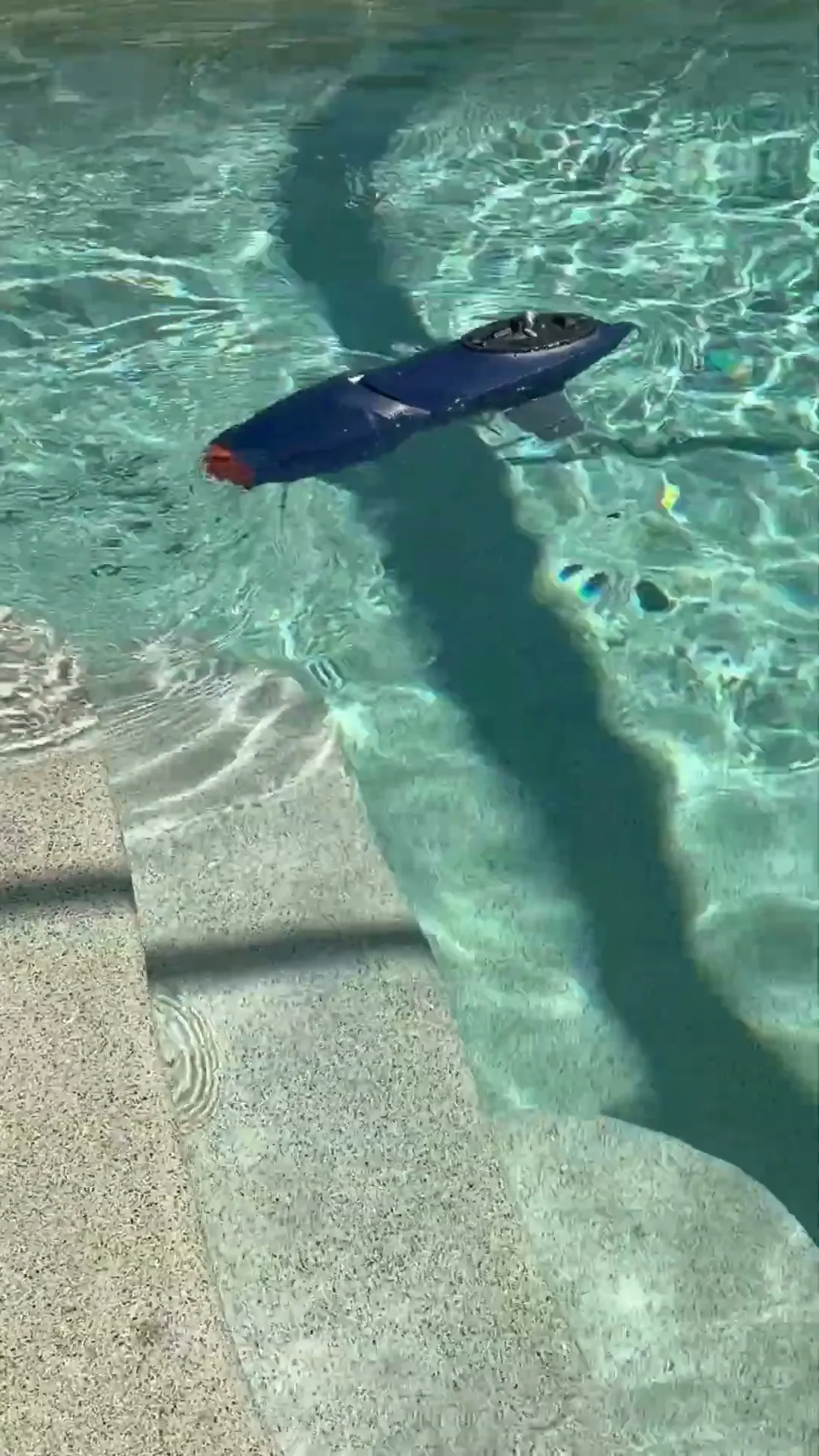
            Well, more fix this and break that in the process... for whatever reason my receiver had a dead channel and i use all of them so got a replacement receiver and set it up and now have lost the telemetry? after trying to trouble shoot it for an afternoon said screw that and need to get this wet and see how its doing. This morning took it out in the pool with some trim weights added (needs more to pull the body down a bit) but drive works, rudder ball doing its job. I'm seeing some thrust torque but can correct with the fins doing a little counter roll. using the fins get it to dive and progressively dives deeper faster, faster, faster then it gets deep enough to lose signal (salt system pool) and then bob back up to the surface. Then the grandson came over for science fair work and when he was leaving asked him to video my next run. i dropped it in the pool (literally, and doing so broke off the internal fin arms - ouch) but was able to get ani idea of the speed again and the rudder working. and the way the fins are fixed you can see it pull the nose under a bit in reverse. GIven i snapped the fin arms i reworked the deisgn for more material and they're working away on the printer, should be ready tomorrow. after that program ballast esc and more telemetry troubleshooting.
             

            Comment

            • Occupant
              Lieutenant
              • Jan 2025
              • 73

              #51
              Another pool day after printing and installing a new set of fins and fin arms. Still seeing a few issues 1) still too light, need weight to pull it under a bit more 2) See thrust torque rotating it a bit 3) once you get a little speed and hit the fins a bit it begins to dive and then just keeps getting steeper and steeper till its nose down ass up, at that point its deep enough the failsafe kicks in and it bobs back up. While I was at it printing new fins I reduced the length of the fin - how much it stuck out from the body by 25% thinking reducing the surface area would slow down the dive. the shorter fins had little effect. next going to try weighing the inputs via transmitter to make it a bit more manageable. I"ve seen the electronics to help stabilize attitude but not sure they would be appropriate here since I have two servos, one for each fin mixed to give pitch and roll - anyone have any experience with setups like this and words of wisdom? One other thing I hadn't considered till today the design is set up for the separate fins to allow controlling pitch/roll, etc to potentially make it behave like a plane underwater. what I hadn't considered is the trim weights and placement with regards to that. I still need to add weight to bring the waterline up higher on the boat, installing the new weights closer to the centerline of the boat may help, but I’m not sure if it will be enough.

              Comment

              Working...