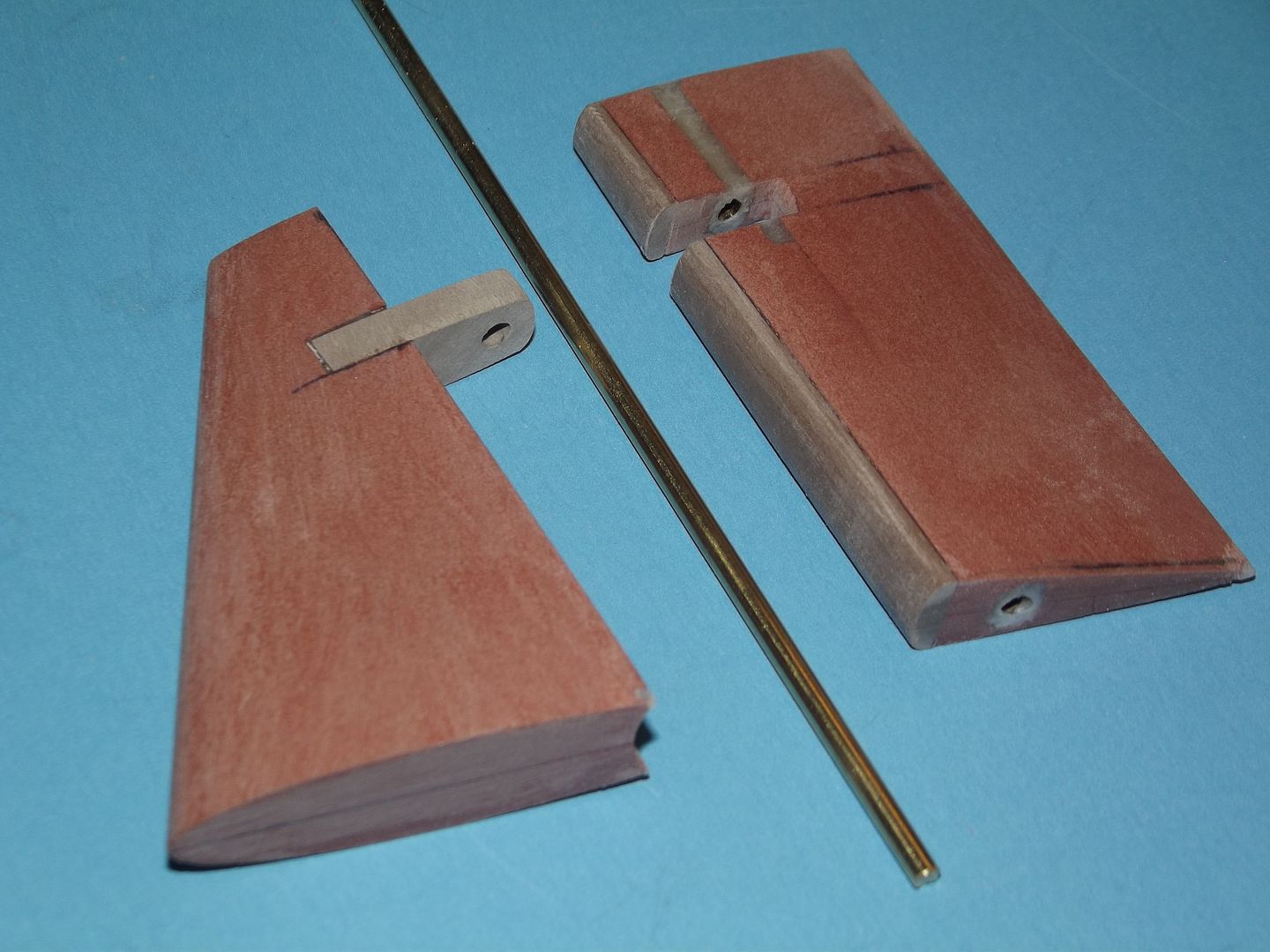
During initial shaping the stern plane was an integral portion of the horizontal stabilizer master. Only after the foil section was shaped was the stern plan cut away from the horizontal stabilizer – leaving two masters to integrate together.The center of rotation, being the operating shaft, dictated the radius of the concave trailing edge of the horizontal stabilizer – dug out with a purpose built gouge; as well as the radius of the convex leading edge of the stern plane – a job best handled by a sanding block.
Each stern planes operating shaft is a discrete item, installed within the stern plane only after the stern planes leading edge had been brought into close proximity to the trailing edge of the fixed horizontal stabilizer. This way the stern plane can nest tightly into the horizontal stabilizer outboard bearing during stern plane make-up to the model.
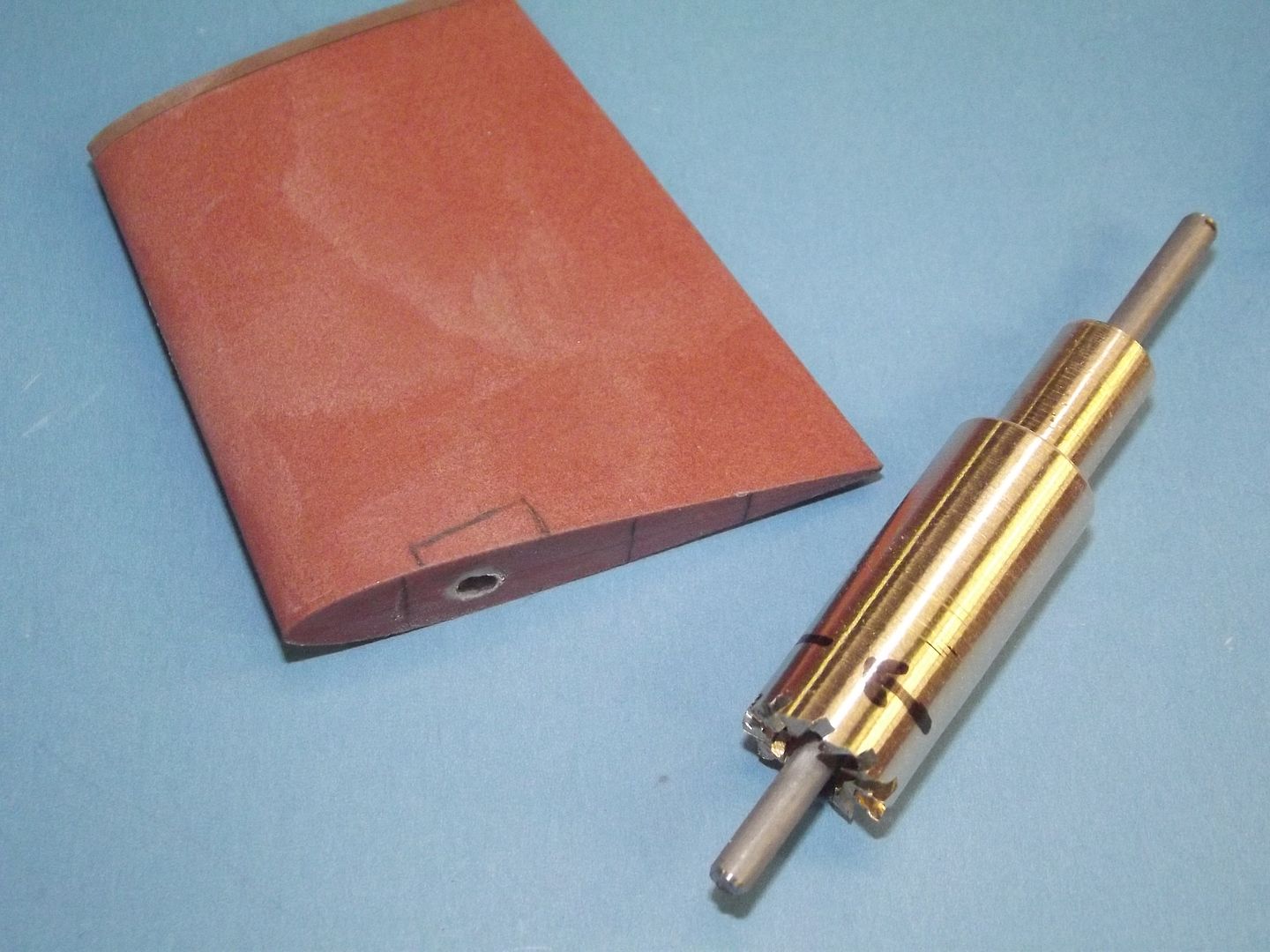
The stern planes and rudders of the PERMIT class boats feature a bearing block that project slightly away from the hull and into the root of each control surface.Through these passed the operating shafts. These bearing blocks are truncated cylinder that fit a similarly truncated bore at the base of each control surface.
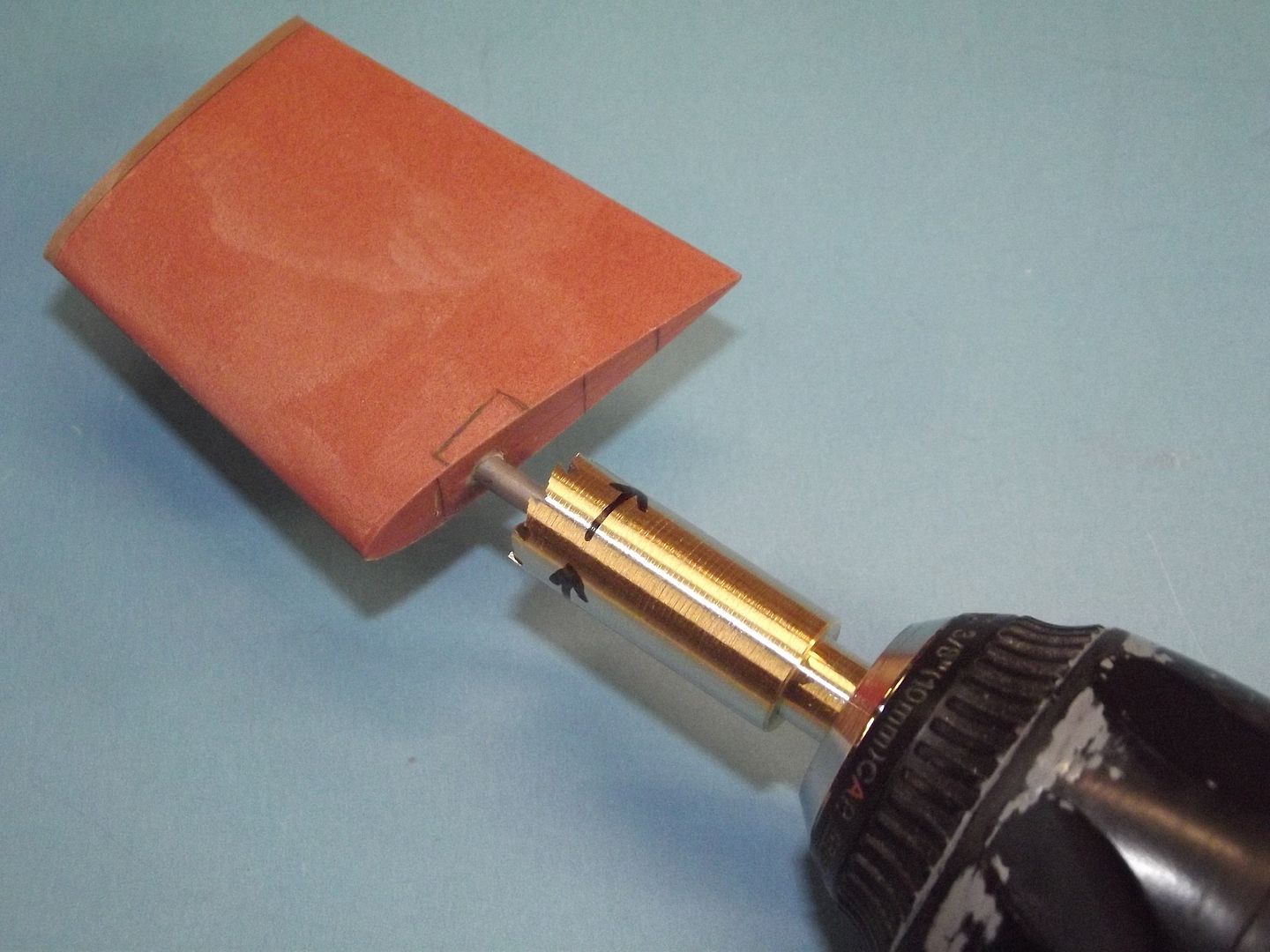
Creation of this bore within the root of the rudder and stern plane was done with this special drilling tool. A length of machine brass round-stock was bored to accept a piece of stainless steel rod equal of the same diameter as the bore of the operating shaft bore already within the master – A length of this rod projected past the cutting face of the tool enough to act as an arbor; keeping the drill centered on the work as the bearing block bore was cut.
(I have found no documentation that the sail plane had such stand-off type bearing blocks).
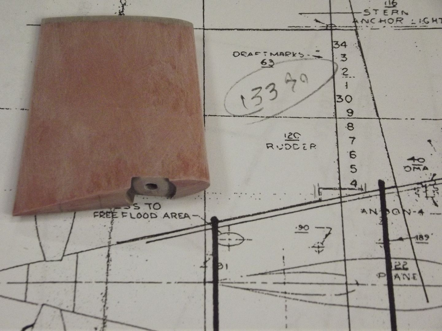
And the result: The properly formed, and functional, bearing block bore ground into the root of the rudder master.
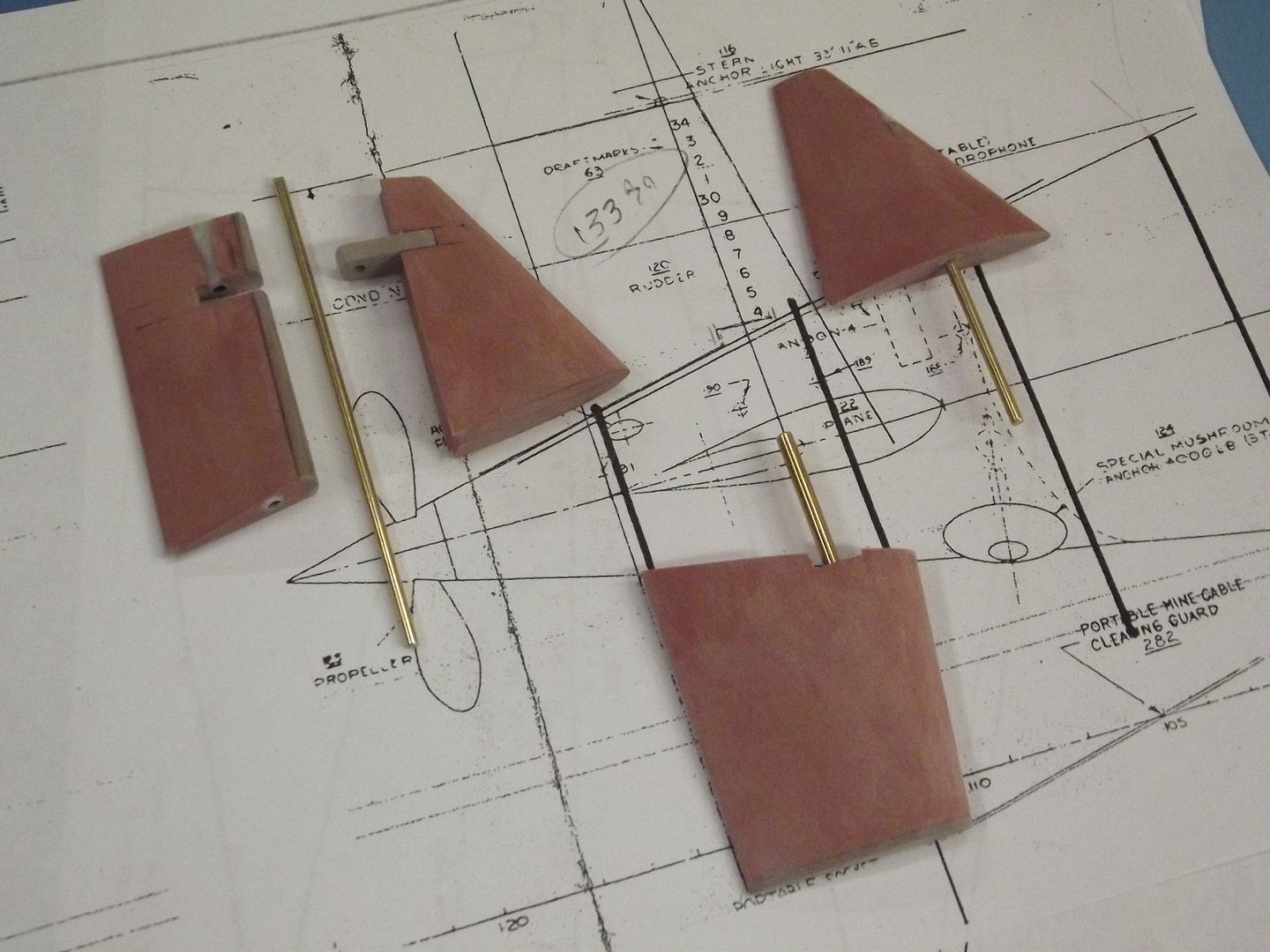
Periodically the masters are checked against the plan. Just to be sure! This particular document is a copy of the NavSea Booklet of General Plans, a grouping of orthographic projections that presents the external shape of the hull, appendages and fittings of the vessel as of the last overhaul.
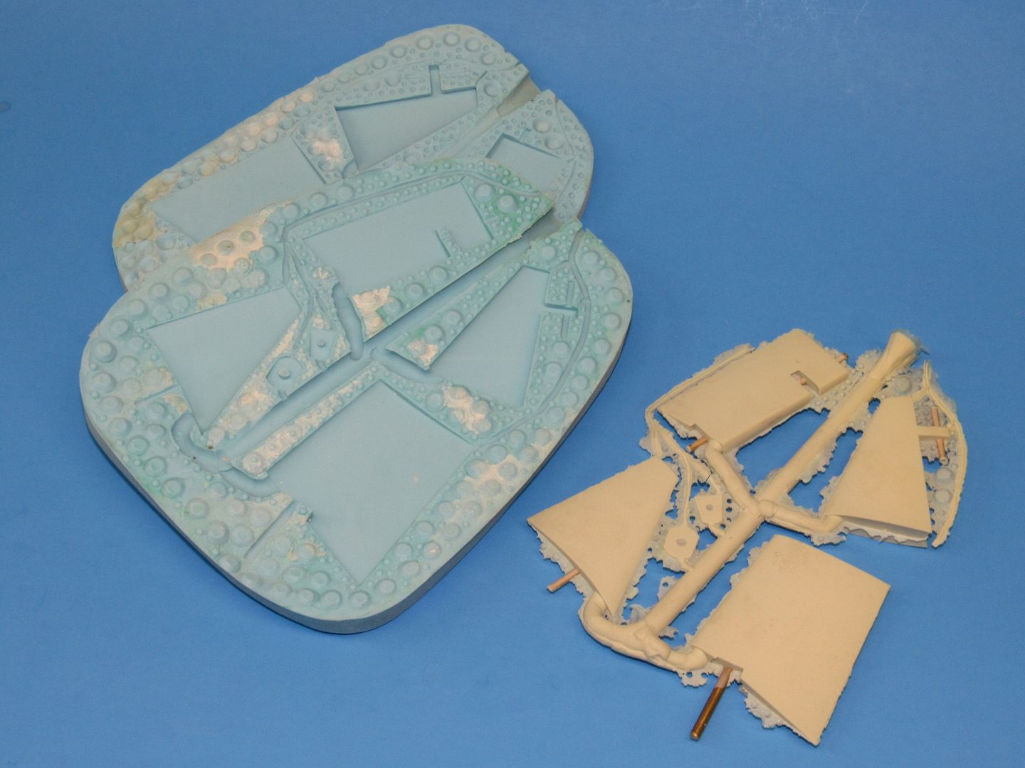
Two sets of cast resin parts for the stern planes, horizontal stabilizers, rudders, fair-water planes and bearing lifts were produced from this silicon rubber tool. Note that brass mandrels are set into the cast control surfaces, these mandrels installed within the tool before the halves were assembled. Removal of the mandrels from the cast resin control surfaces left perfect bores that would later accept the operating shafts installed later that transmitted the torque forces needed to move them in a controlled manner.
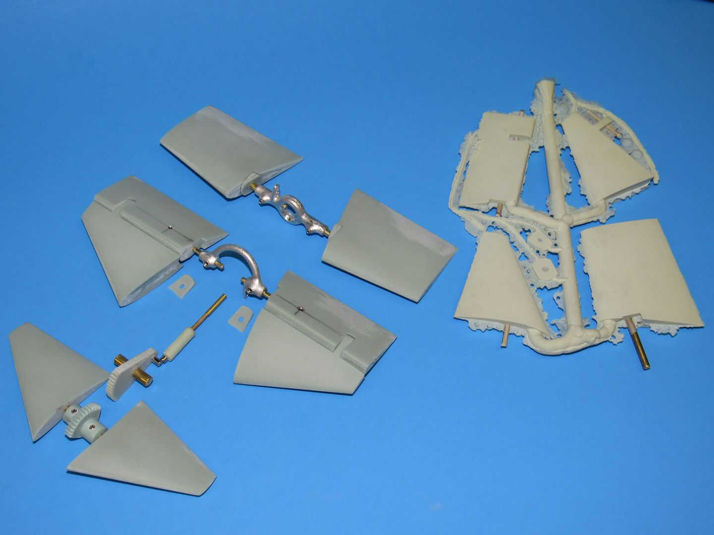
The linkages for the sail-planes (fairwater planes in some snooty circles), stern planes and rudders were lifted from the 1/72 SKIPJACK fittings kits I produce. Here you see things mocked-up so you get an idea how things worked. Note the use of set-screws in the stern planes (these will be on the bottom side of the stern planes where they typically will not be seen) to make fast the operating shaft so that the torque applied to it will deflect the planes as desired.
The shape of the cast white-metal yokes permits passage of the centrally running propeller intermediate drive shaft. The model yokes are almost direct analogs to the actual yokes seen on the real submarines.
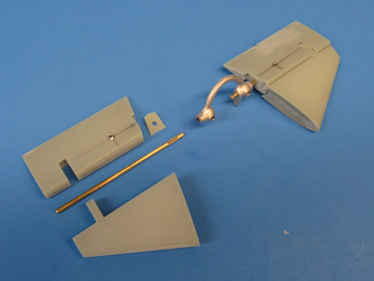
Once the fixed horizontal stabilizer is bonded to the after end of the hull, the problem becomes how to neatly nest the stern planes outboard bearing gape into the horizontal stabilizers outboard bearing. Doing so mean that you could not fix the stern plane operating shaft in place, as it would preclude such assembly.
A stern planes operating shaft is introduced into the outboard end of the stern plane, passed through the hole near the tip of the horizontal stabilizers outboard bearing – binding the two together at that point, the operating shaft then run into the hole set into the side of the hull – binding the stern plane to the hull, and the operating shaft inboard end projecting into the bore of the yoke.
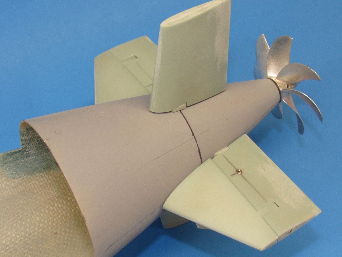
And the work as of today. I have yet to bond the horizontal stabilizers to the hull. Here the stern planes are on upside-down to show off how the set-screws are used to affix the stern plane operating shafts in place. In practice, these unsightly fasteners will be on the bottom, given little notice by the casual observer.

Comment