-
-
-
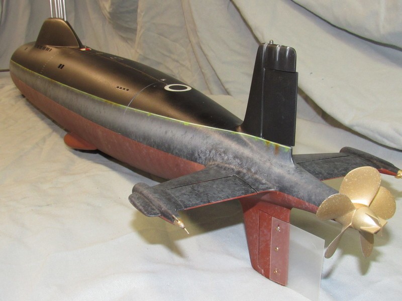
Beautiful! Very tight turning radius. You got that beast running great, Scott.
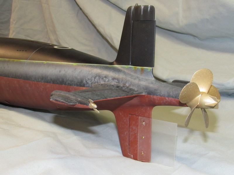
I'll have to retain the lower fixed vertical stabilizer as I'm not using a yoke, and the single-point support of that operating shaft necessitates use of the upper stabilizer bearings. (Let me guess: you're constantly bending the lower rudder operating shaft?).
However, I'll do what I had to do on the 1/72 ALFA to fix the poor turning of this boat: I'll bolt a clear plastic rudder extension aft of the lower rudder -- that's the only way I've found to retain some semblance of scale fidelity and still realize a reasonable turning radius.
DavidWho is John Galt?Comment
-
I can see it now! Nice. that extension makes a world of difference.If you can cut, drill, saw, hit things and swear a lot, you're well on the way to building a working model sub.Comment
-
The lower operating shaft is 2mm stainless steel in a brass mounting. Hasn't bent yet. The propellor that I stole from you!
Comment
-
That photograph didn't re-size for some reason. Once more:
Comment
-
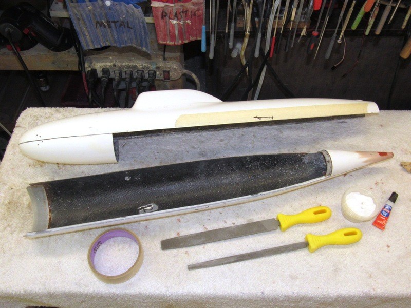
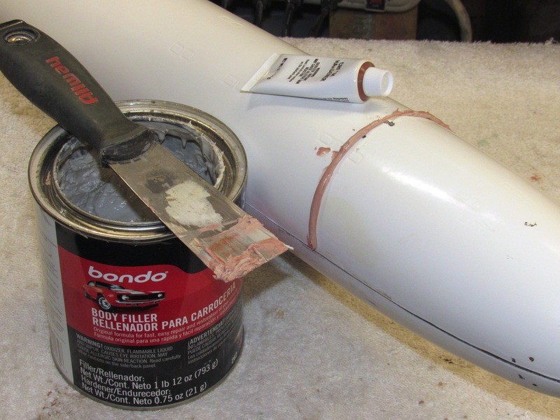
Bouncing the models length against 1/96 drawings I found the stern, where the propeller hub would butt, was too big in diameter, and short about 3/8”. As the stern is a cone, lengthening it would produce a smaller diameter at the stern. So lengthening the hull at the stern would solve both issues.
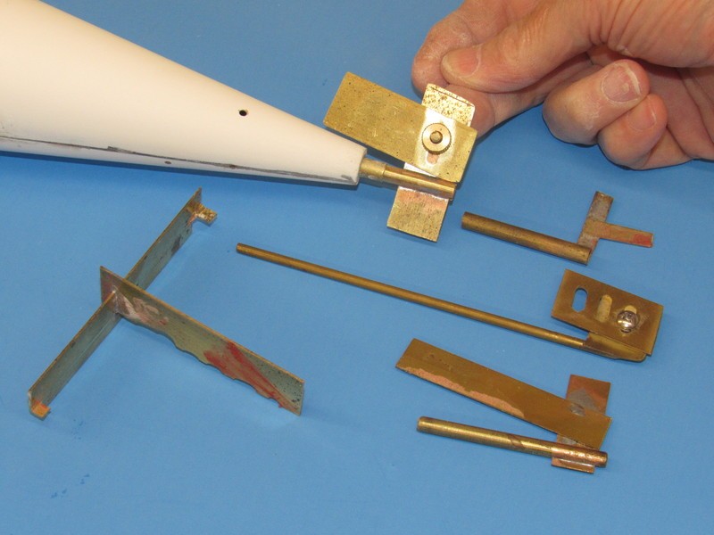
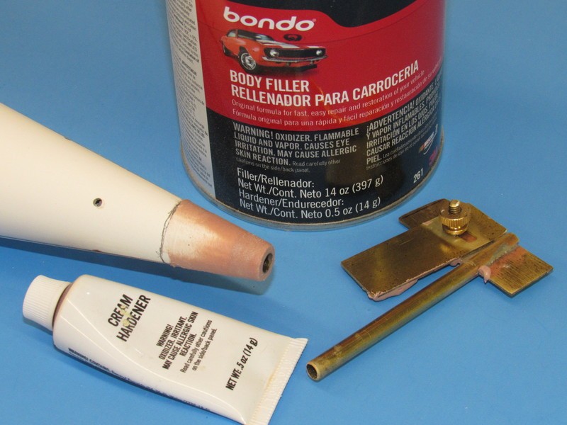
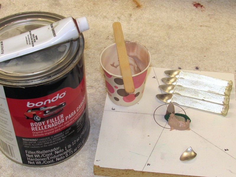
I employed a radial screeding tool to build up a Bondo stern extension over a brass tube, which served as an Oilite bearing stand-in. In the photo you see the purpose built tool for this job as well as a selection of other radial screeding tools used on other jobs. The T-shaped item is a linear screeding tool used to form mast fairings – use of that tool discussed at my DANIEL WEBSTER WIP post.
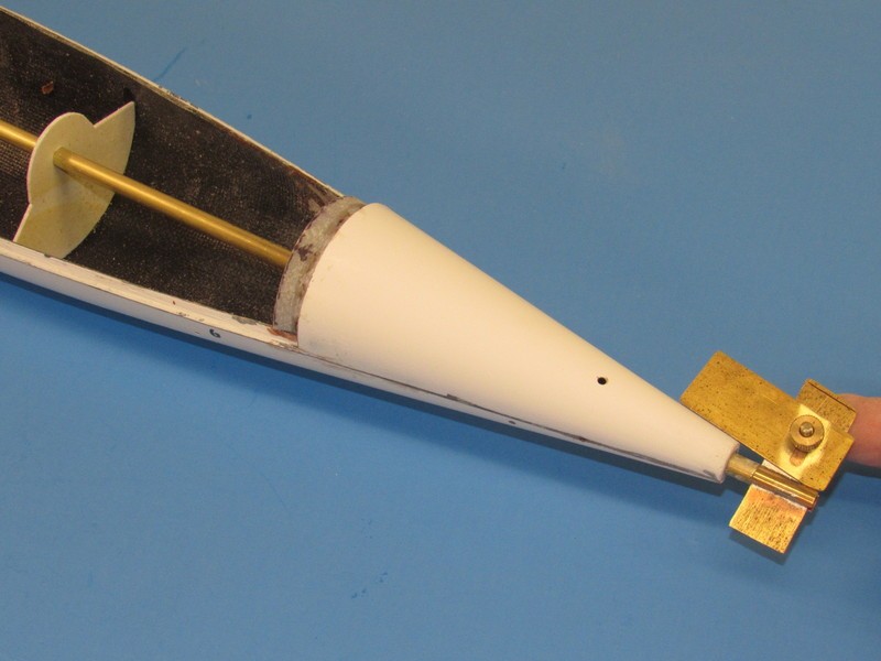
The outside diameter of the temporary brass tube within the stern equates to that of the eventual Oilite bearing that will replace this tube at the stern. I took care to center this tube with the hulls longitudinal axis with the white plastic temporary bulkhead you see at the extreme left.
The after end of the brass tube was coated with wax so as not to stick to the hardened Bondo during removal. To reiterate: the brass tube forms the bearing within which the screeding tool spins along the longitudinal axis of the hull, and once the tube is extracted it leaves the bore into which the Oilite propeller thrust bearing would be inserted.
It took three passes to get a flaw-free build-up of Bondo that formed the stern extension, but the work went quickly and the tool produced the desired near perfect round, tapered section.
Note that the screeding blade is adjustable, making the tool adaptable to other like jobs.
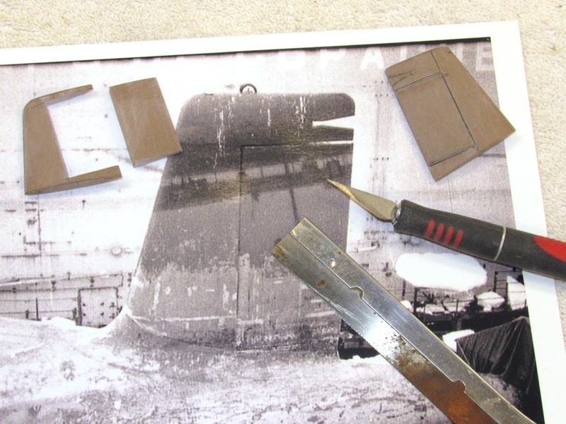
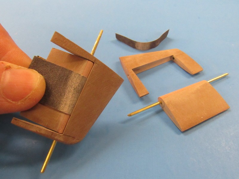
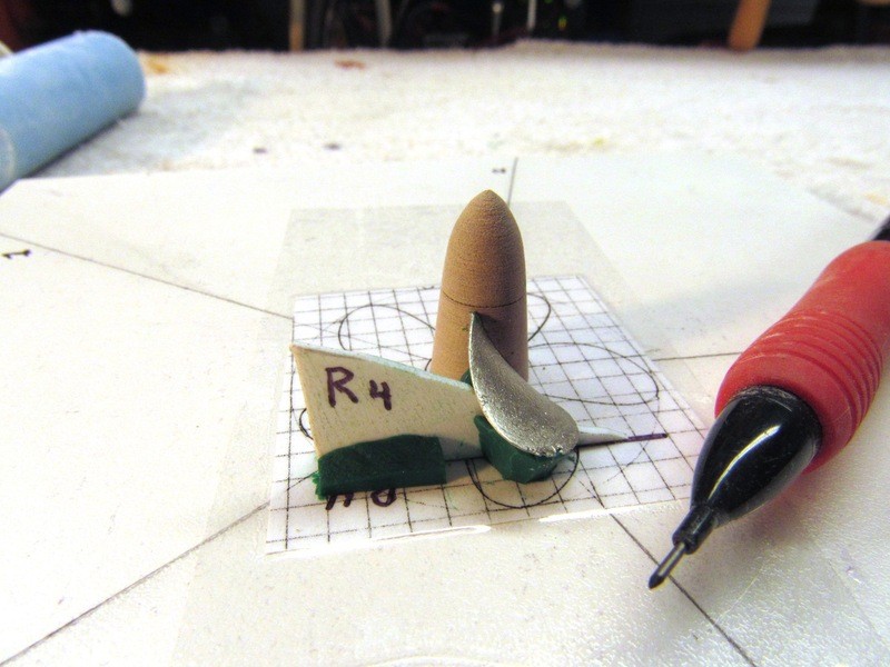
Cutting the rudder away from the surrounding stabilizer was the easy part, done with knife and razor-saw. The difficulty laid in carving out the concave ‘trough’ within a stabilizer needed to clear the rounded leading edge of the built-up rudder. Which brought up the other problem: the need to add another piece of RenShape to the leading edge of the rudder to form the half-cylinder shape required – eventually the leading edge of the rudder would nest, with a little clearance (an annular space of about .015”), into the trough of the stabilizer. Adventures in model-building!
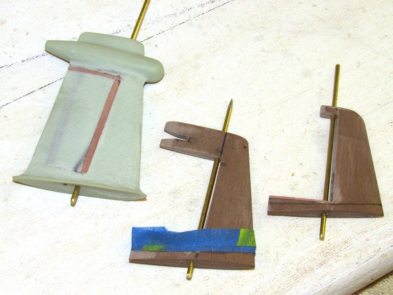
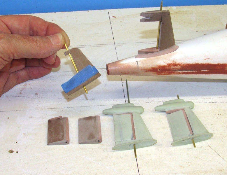
To the left is the upper vertical stabilizer with its installed rudder. Note how the upper and lower portions of the vertical stabilizer form the two support bears that keep the rudder in place but free to rotate about its operating shaft. To the right are the yet-to-be-assembled lower rudder pieces and its vertical stabilizer.
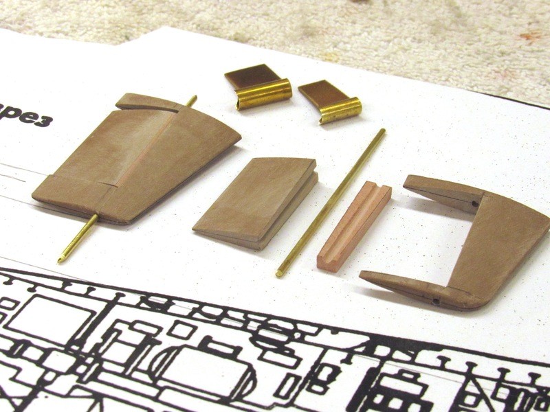
As you recall the vertical stabilizers and rudders were formed from a single blank. Only after profile and sectional shaping had been completed were the rudders cut and sawed away from their vertical stabilizers.
Special gouges were made from brass tube and strip stock. These were used to dig out the trough within each stabilizer. Once the rudder leading edge piece was glued to the rudder it was worked with file and sanding block to a semi-cylinder whose forward area nested within the concave trough of the vertical stabilizer.
Yesterday I laid up two radial flange pieces from multiple layers of glass and epoxy laminating resin. This morning I took the cured pieces off the hull portions that gave them their correct shape for installation. They were cleaned up on the sanding machine and cut to fit the forward and after radial edges of the lower hull.
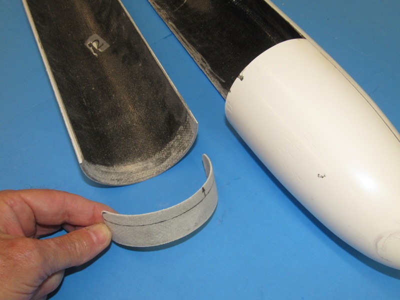
The larger forward radial flange is bonded to the forward radial edge of the hull, and the smaller after radial flange is glued to project a bit forward of the after radial edge.
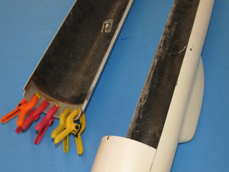
The radial flanges were attached with epoxy laminating resin thickened with micro-balloons.
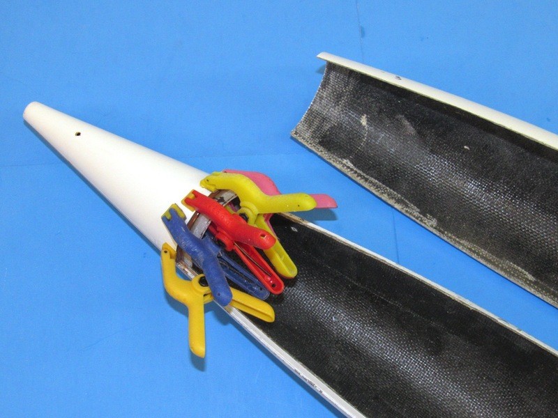
This Z-cut, with the longitudinal and radial flanges insures good tight registration and assembly of the two hull halves, needing only a single machine screw at the stern to hold it all together.
Who is John Galt?Comment
-
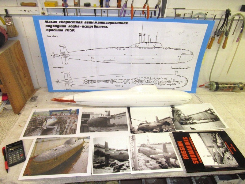
Just some of the documentation broken out and arranged for easy examination as I work up the propeller, and prepare to engrave the hull with a much more accurate representation of the hatches, access plates, limber holes and other openings unique to this class of Soviet … err …. Russian submarine.
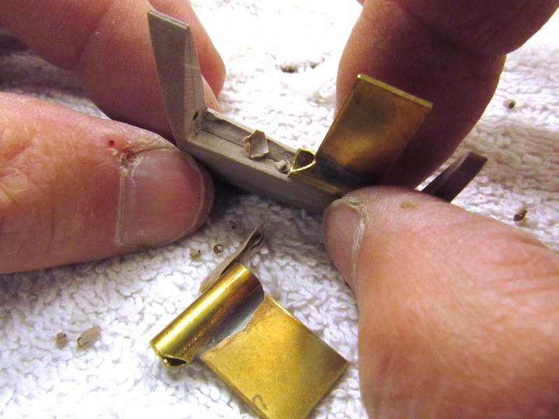
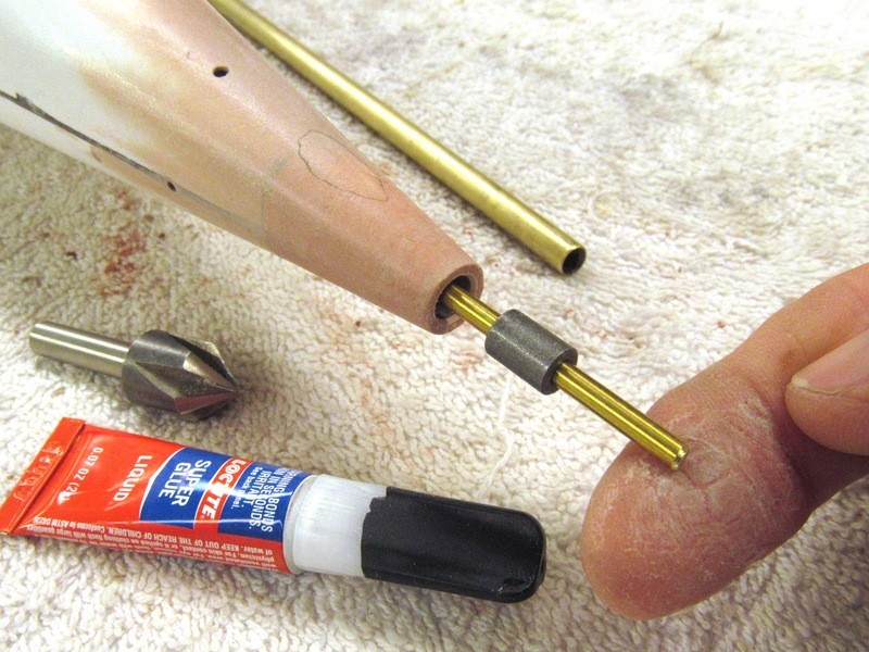
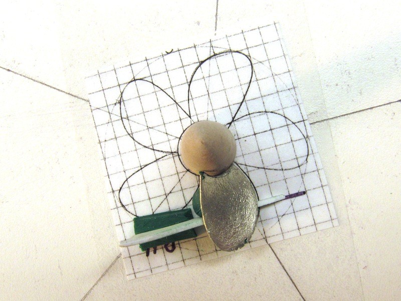
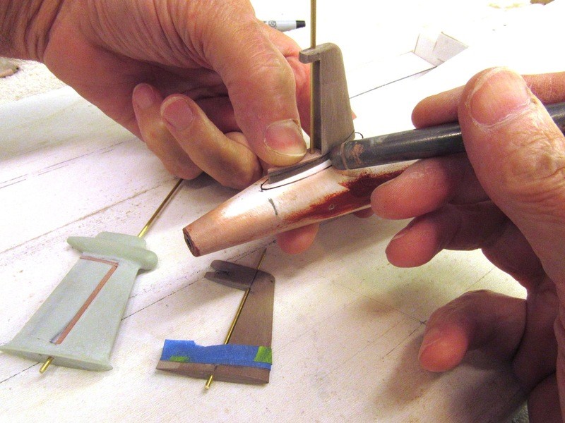
Final work on the rudders to get the stabilizer troughs ground to the correct depth and shape. An old trick: to one of the parts that will either mate or be in close proximity to the other affixed a piece of sandpaper and rub the parts together until the face of one part matches a face of the other part.
In this case a strip of sandpaper is wrapped around the leading edge of the rudder, the rudder installed to the stabilizer, and the rudder rotated, grinding the stabilizer trough to final shape.
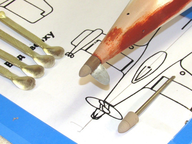
A little more work at the stern with Bondo. After sanding smooth – Bondo is a weak and water absorbing substrate – the work was coated with a layer of CA adhesive, this greatly strengthens the two-part filler and makes it resistant to water.
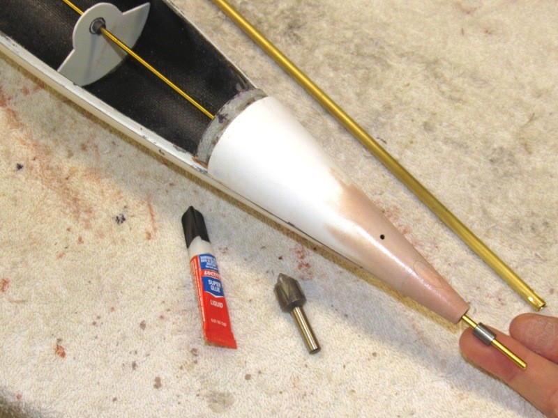
The brass tube, of the same diameter of the eventual Oilite bearing that would fit at the stern, was twisted a bit, breaking the weak bond between its end and the Bondo, and pulled forward and out of the hull. Here you see a test fit of the bearing that will be permanently CA’ed in place.
I was disappointed to find that the longitudinal edges between the two hull halves was uneven – in the case of the upper hull the edge was so formed that portions had to be re-built. With the lower hull, the half outfitted with the longitudinal indexing flange, its longitudinal edge was found to be severely warped.
Were the upper hull edge had to be built up I employed CA and baking soda, using the edge of masking tape to define the location and height of the build-up required to straighten the edge. The lower hull distortions were ground away with moto-tool and file. It took an entire day to get the upper and lower hull to match up together without significant gapes or binding!
Bondo (trade name for a common two-part, polystyrene automotive filler) was used to tighten the gaps at the forward and after radial seams. Here I’ve just placed some catalyzed Bondo to the forward radial flange and assembled the hull halves. Of course, before that I had waxed the inside of the upper hull so no Bondo would stick to that. Once the Bondo cured hard the halves were pulled apart and the excess Bondo filed and sanded away.
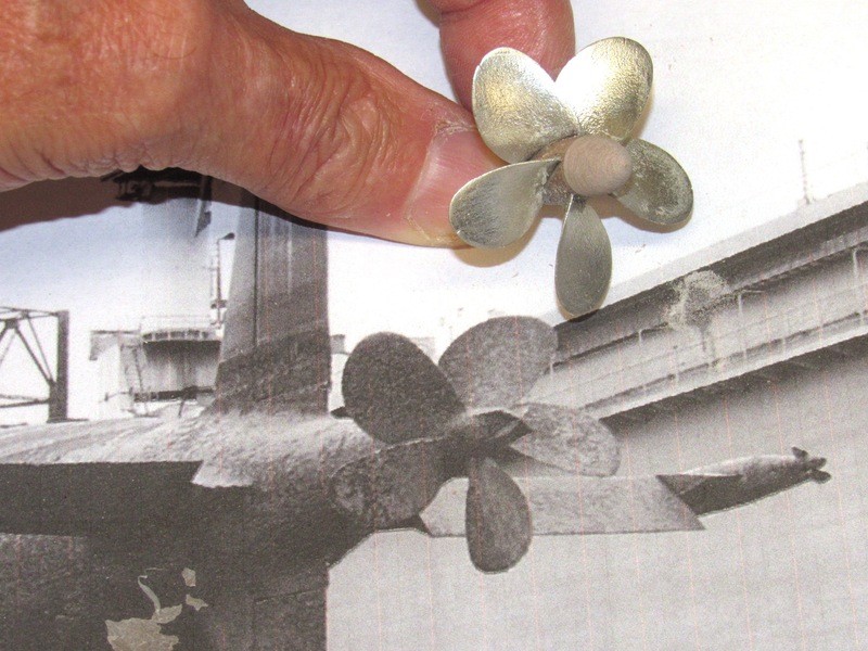
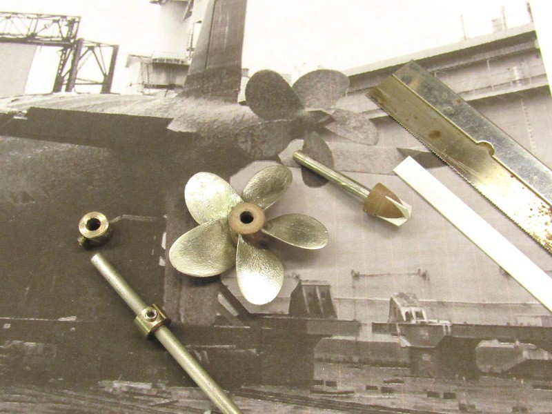
Work on the propeller started with a close examination of what photos I could find of an ALFA’s propeller out in the wild. In recent years more and more of this kind of neat stuff has appeared on the Internet, so I keep looking for chestnuts like these.
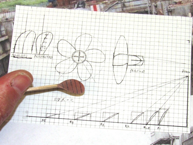
Once I have a reasonable idea of the geometry of the blades and hub I prepare a ‘blade-chart’. This document defines the shape of a blade, both projected and developed – the developed shape derived from the angular displacement (difference between apparent and actual shape), revealed as specific radius points along the span of the blade are laid once the pitch is determined.
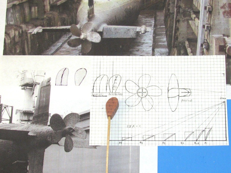
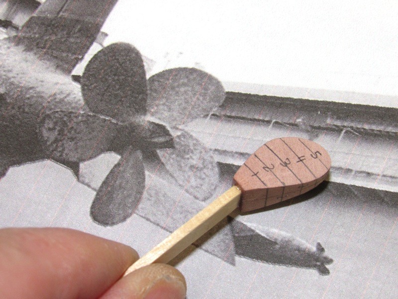
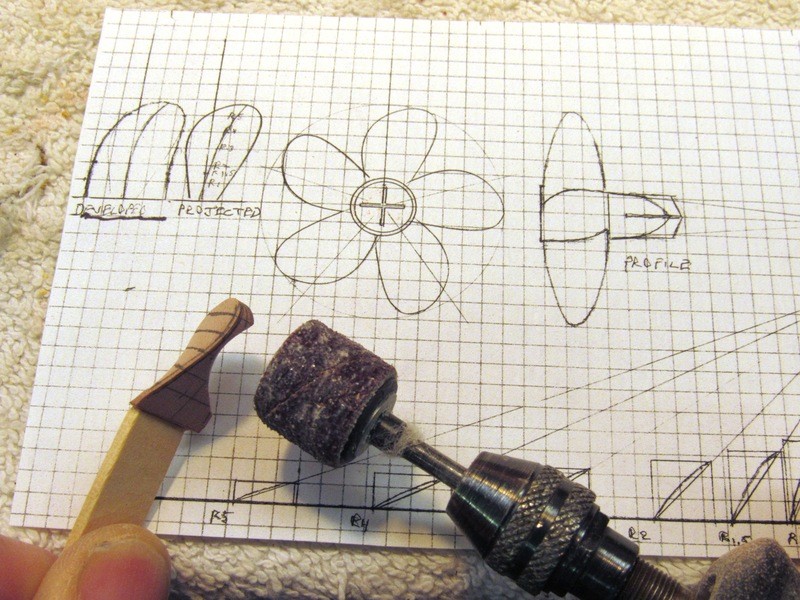
Working off the blade-chart I cut a blade blank from RenShape and got to it with moto-tool, knife, and file. The eventual propeller blade master will be used to make a rubber tool, from which I will cast five white-metal blades, and assemble those around a RenShape hub, forming the propeller master.
Three assumptions had to be made, as I’m not on the Malachite design bureau’s mailing list: The propeller is of the constant pitch type (All radius points along the span advance the same linear distance with each rotation of the propeller); total developed blade area is between 60-70 percent of the disc, less the hub; and that the pitch equals the diameter of the propeller – a bit arbitrary, but a default ratio that has served me well over time.
Who is John Galt?Comment
-
I love reading this stuff - and I love the thought of you working away with a big grin on your face whilst you do it. Some things are better than money - speaking of which, I'd like to give you some money for one of those bright, new, shiny Alfa props when they get done. I mean it; no freebeeies - cash transaction.Comment
-
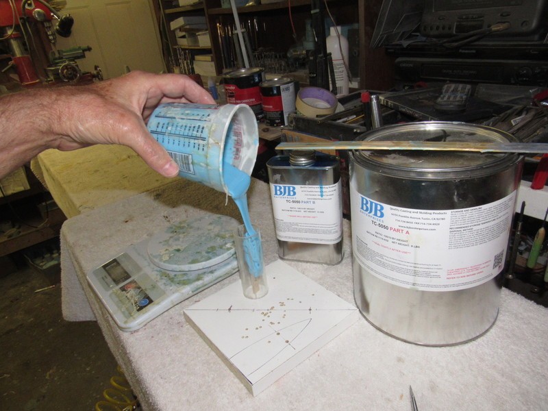
The popsicle stick handle I used to hold the work as I formed the blade master now serving as a sprue extension had its base affixed to a mold-board; a length of clear Lexan tube used as a flask to contain the RTV silicon mold-making rubber; rubber mixed up, de-aired, and poured into the flask, encapsulating the master forming the propeller and sprue cavities required for metal casting. Once cured hard the rubber tool was removed from the flask, and the rubber split along its length till I could withdraw the master.
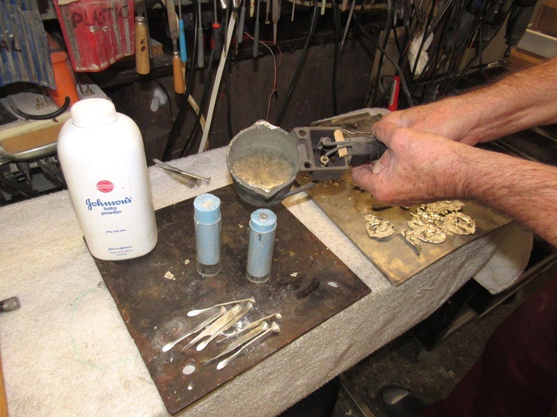
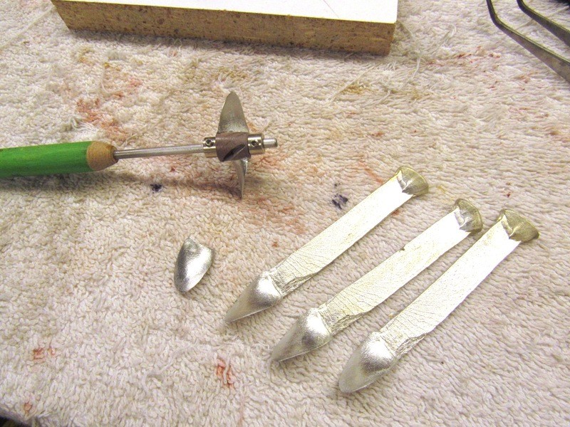
I cast up ten white-metal propeller blanks. Nothing fancy -- just, ‘leadless solder’: 95 percent Tin, 5 percent Antimony. Melts at about 500 degrees. The TC-5050 BJB rubber I use can tolerate that kind of temperature all day. Production goes fast, as quick as I could pour, de-mold, and pour again was the speed of things. And I get rock-solid parts that are easily machined, and exhibit no shrinkage of the parts -- white-metal actually expands as it changes state from liquid to solid! Beautiful stuff.
Though I was building a five-blade propeller master I needed in excess of that one blade, trimmed short, to butt up against the hub, using it to mark off where to cut slits into the hub; and another blade, cut to a length that would fit within the slit, that blade used to mark off the production blades that would be bonded to the hub. The other extra blades, like the extra hub-dunce cap, were just there for insurance.
I turned two propeller hub-dunce cap assemblies from RenShape. Never hurts to have a back-up for operations that might require a ‘do-over’. I was taught this and many other tricks by the finest model-builder I’ve known: the one and only, Ben Guenther.
(Ben is a retired NASA-Langley model-shop supervisor – he’s done and seen some weird **** in his time. Today he specializes in very small scale armor, air, and spacecraft models. All scratch-built and with a fidelity to prototype that is near photo-perfect. The array of skills Ben has is unmatched in the world I know. Not only that, but this true Master of the craft is the calmest, most soft-spoken person I’ve ever dealt with in this arena. You have to see he work to believe it:

http://www.missing-lynx.com/gallery/...ri144bg_1.html)
Ben has taught me so much! I will always be grateful to him and the other Masters who so freely share their skills and findings with the rest of us. Because of these guys the Craft will survive.
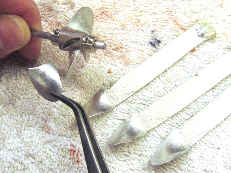
Each metal blade would fit a slot cut into the side of the propeller hub, everything indexed properly on a ‘propeller assembly jig’. First task was to cut one of the metal propeller blanks so its root butted up against the side of the hub as the blade was positioned to the correct pitch, skew, and rake angles – temporary support of the blade achieved with some oil-based clay between the blades pressure face and jig.
While so positioning the correct pitch was assured by an angled piece of plastic sheet set between pressure face and jig. Once happy with the blade-to-hub orientation I penciled onto the side of the hub the outline of the blades root.
Note that I’ve temporarily taped a copy of the propeller blade-chart plan view atop the propeller assembly jig, this illustration serving to both identify the specific radius points along the span of the blade, but also a visual reference to guide me as I set the skew angle between blade and hub.
Removed from the jig, the hub was then hollowed out between the pencil lines and a propeller blank – its root extending about 1/16” into the slot – inserted and CA’ed in place. This work done on the assembly jig to insure correct positioning as the glue set.
The first production blade in place I pulled the propeller master off the jig and jammed it into the stern of the ALFA’s stern. Looking good! Now, with confidence I set about the task of outfitting the assembly jig with a blade support crutch that would insure symmetry of all blades as they were glued into the hub.
Back on the blade assembly jig a Bondo blade crutch was formed by shoveling mixed Bondo between the pressure face of the blade and the surface of the jig. Prior to that, the blade was coated with wax to prevent adhesion between it and the Bondo. Strips of clay were used as dams to insure a complete fill of Bondo between blade and jig.
Not apparent in the photos each blade has a shallow indentation at its tip, an indexing mark. During blade assembly to the hub these marks would align over a radiating line from the center of rotation – this to assure symmetric spacing of the five blades about the hub.
Here, not yet trimmed, is the hardening Bondo and portions of clay used to direct it between blade and jig.
While in a ‘green’ state (hard, yet soft enough to cut with a knife easily) I trimmed away excess Bondo from atop the blade and around the blade edges. Waiting a few more minutes for the Bondo to harden a bit more I pulled the blade-hub assembly away from the jig, revealing the ready to use blade crutch. This is how blade rake, skew, and pitch symmetry is achieved for all blades.
Most apparent here is the severe helical twist of the blade – a consequence of the high pitch of the ALFA propeller. Remember, that wheel was designed to push that submarine to nearly fifty miles per hour, submerged! That’s a lot of thrust; a lot of water to bite and push around at a high rate. The ALFA propeller is a monster! God damned Soviet’s! They make the neatest looking boats and planes!
Who is John Galt?Comment
-
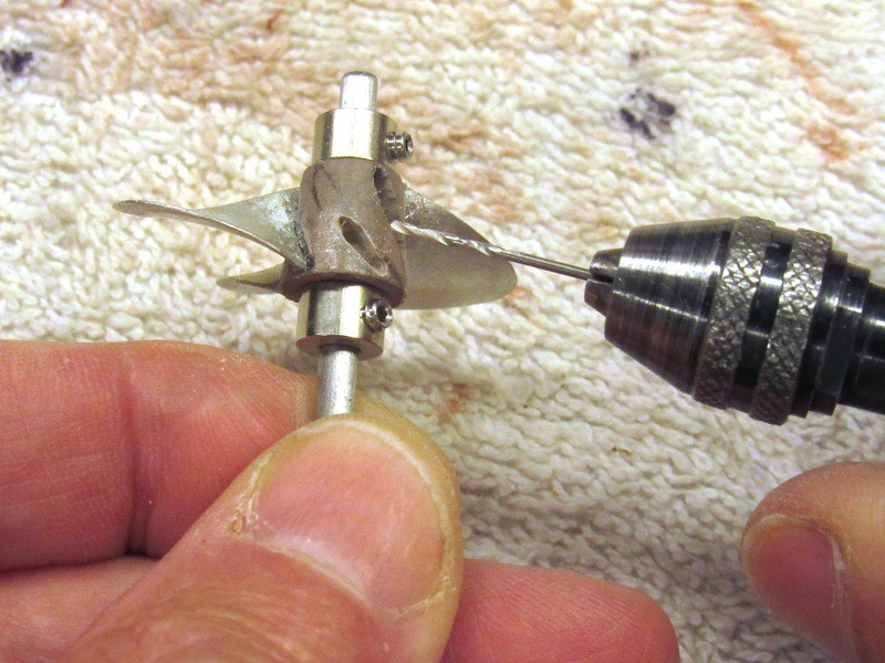
And here is how the five white-metal blades were assembled to the hub with assured symmetry of blade spacing, rake, pitch, skew, and radius. The ‘finger’ and thumb-screw works to hold a blade in place atop the blade crutch as the tight void between its root and hub is filled with CA and catalyzed with baking soda and a shot of liquid ‘accelerator’.
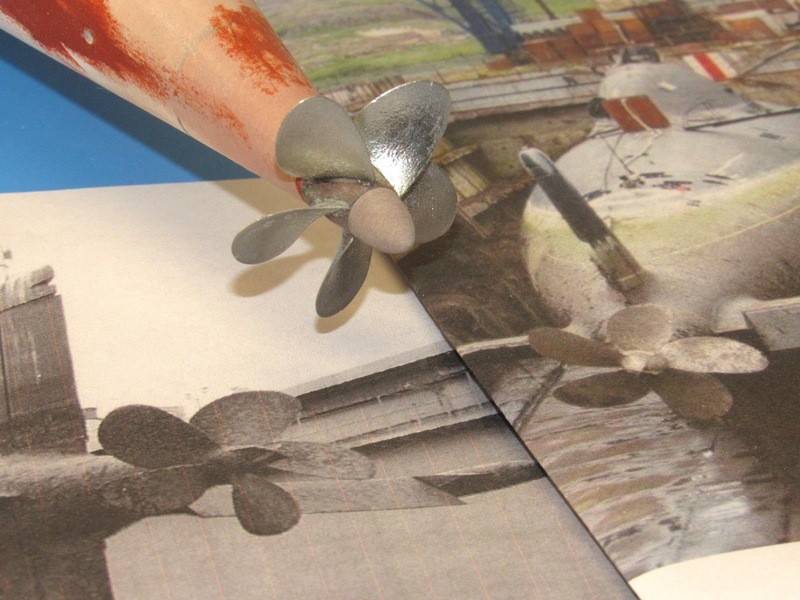
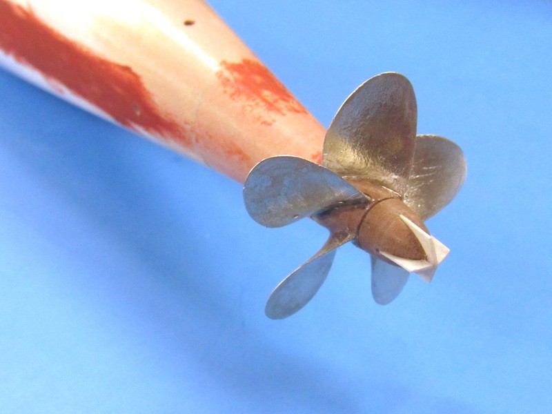
Just for fun I oriented the raw assembled propeller to correspond to the aspect this picture of the real ALFA propeller was taken. “Close, Ward … very close”.
Basic assembly of the 1/96 ALFA propeller is done. Lots to do yet: build up the fillets between blades and hub, build-up the vortex attenuator plates at the after end of the dunce-cap, and a lot of etching-priming-sanding-putty-etching-priming-sanding-putty-sanding-etching-priming and finally rubber tools for production of propeller and dunce-cap kit parts.
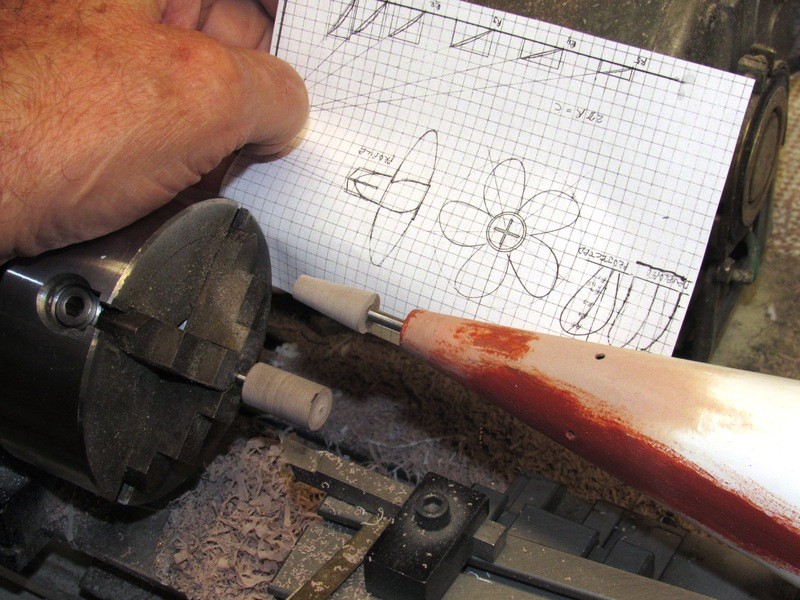
The handle permitted me to more easily maneuver the hub as I milled out the recess and test fitted a blade.
Only after I was reasonably sure the blade would fit did the hub go back onto the jig. Note that a wheel-collar at each end of the hub secured it firmly to the handle.
Using a .052” drill as a hand-held milling bit I dug out the recess in the hub to accommodate the root of a propeller blade. The recess to the right is done, and you can just make out the pencil outline of the blade root on the partially milled out recess at the center of the hub.
With the hub mounted on the propeller assembly jig, the short ‘marking’ blade was used as a stencil to indicate where the hub had to be dug out to make room for a propeller blade root.
A blade is then positioned over the blade crutch and examined to insure that it sits flat on the crutch with no binding between the blade root and sides of the hub recess. The blade in place on the crutch I made up the securing brass ‘finger’ to keep the blade from moving as it was permanently bonded to the hub with CA.
Last edited by He Who Shall Not Be Named; 07-05-2019, 08:23 PM.Who is John Galt?Comment
-
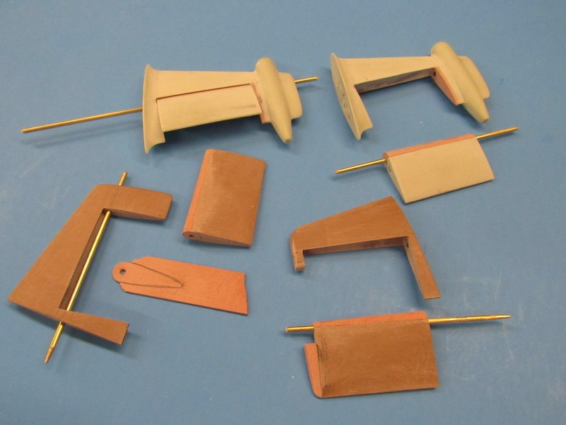
The cast resin horizontal stabilizers (originally production kit parts, but these two here pressed into service as masters that were further worked to produce practical stern planes) and their imbedded stern planes were addressed with razor-saw and cut-off wheel to free the planes from the stabilizers. I incorporated stern plane operating shafts, operating shaft plane bores, and stabilizer plane operating shaft bearings (bores at the base and tips of the horizontal stabilizers to make the control surfaces practical. Material lost to saw and wheel kerf was made up with slivers of RenShape.
The upper and lower RenShape vertical stabilizers and rudders received the same treatment.
All control surface operating shafts are 1/16” diameter brass rod. At this point all attachments were done with thin formula CA adhesive.
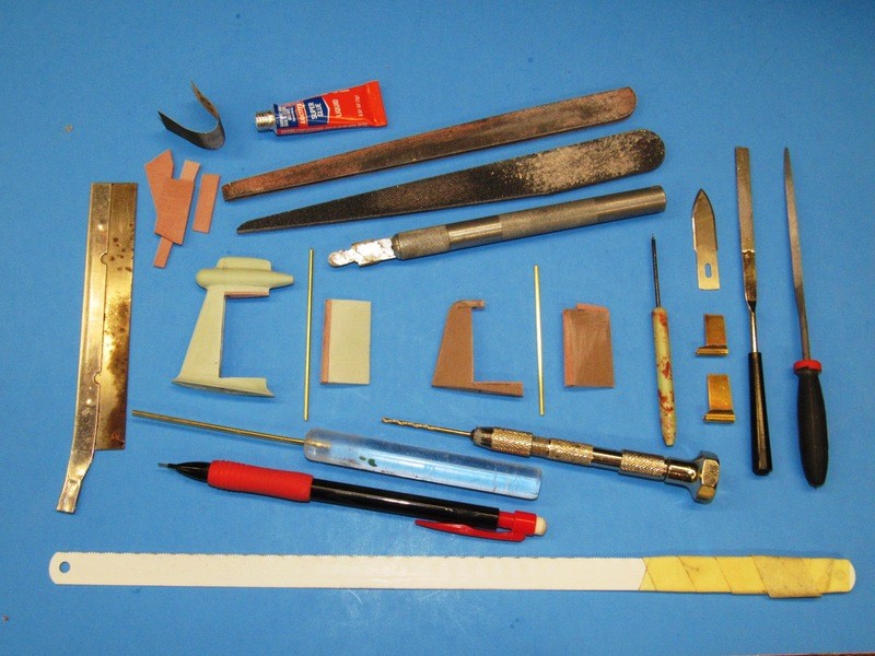
Some special tools were involved in this work: The tubular gouges were needed to rough out the troughs within the vertical and horizontal stabilizer masters; a half-disc shaped knife blade was ground to shape, this tool to plane the flats of the stabilizers where the upper and lower edges of the rudder and stern plane masters interfaced with their respective stabilizers; and purpose cut sanding sticks and round files helped refine the stabilizer fillet work.
I was remise in not showing the dapping tool pressed into service as a fillet screeding tool – used to produce a constant radius fillet along the base of the two vertical stabilizer masters.
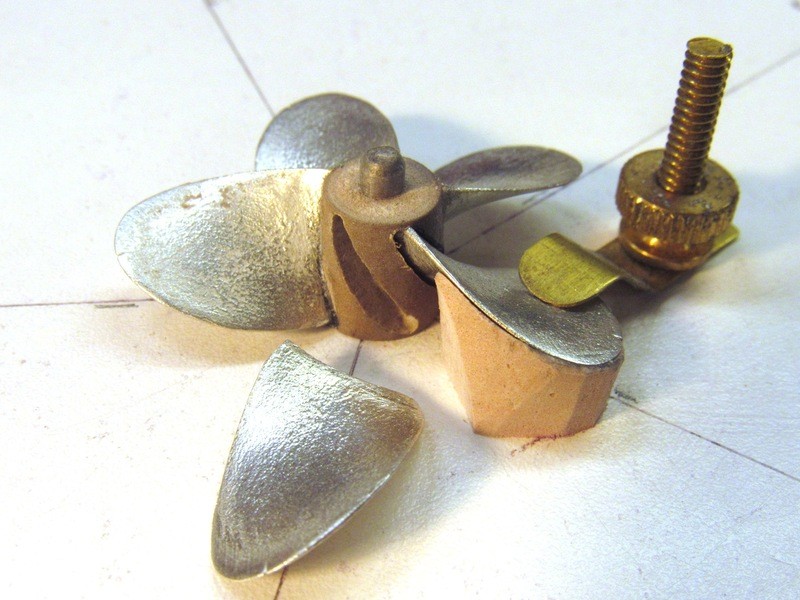
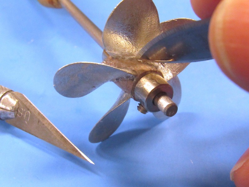
First task after removing the just assembled propeller master from its assembly jig was to cut and scrap away excess CA adhesive from the roots of the blades and around the hub. Note the use of a handle – the hub of the propeller held tight on the handle shaft by sandwiching it between two wheel-collars.
The cutting and scraping alternated between a straight and curved edge knife, the choice of tool driven by which side of the blade I was working: the highly convex curved ‘suction’ side of a propeller blade was addressed with the straight blade; the flat, nearly concave ‘ pressure side of the blades worked with the curved blade. Right tool for the right job!
Small radius fillets between propeller blade roots and hub was the next objective. Several layers of thin formula CA adhesive were carefully worked into the creases with a pointed piece of 1/16” brass rod. Capillary action is our friend! After each layer was put down, the propeller master was hit with a good spray application of CA ‘accelerator’ to harden the glue. The built up fillets were given final form with a very small rat-tail file and a great deal of patience.
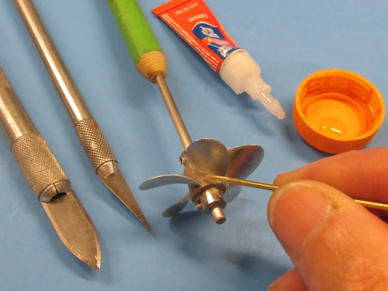
Careful work with .020” plastic sheet and a RenShape dunce-cap resulted in a fair approximation of the iconic Soviet type propeller vortices attenuator. Two razor-saw axially directed slits, situated ninety-degrees from each other, at the after end of the dunce-cap, accommodated the two strips of plastic sheet.
To the left you see the 1/8” diameter shaft of the handle I use to hold the propeller master as I work it. Evident are the two wheel-collars that compress the faces of the hub to hold it in place on the handle and keep the work from rotating as I work with knife and file.
Carefully cut slits in the RenShape dunce-cap permitted me to slide in two pieces of internally slotted plastic sheet. After gluing these in place they were cut to profile. Here I’ve temporarily mounted the propeller-dunce cap assembly onto the hull, just to see how things are shaping up. Looking good!
The upper edge, where the eventual fillet would fair into the surface of the vertical stabilizer was marked with the dapping tool itself. Running the dapping tool head along the hull and sides of the master left a slight mark. That mark on the vertical stabilizer was later enhanced with pencil and masking tape applied above the pencil line. That tape to prevent excess Bondo from marring the work above the fillet during the build-up operation. A little care at this point saves a lot of clean-up work later.
The enhanced line denoting the top edge of the eventual fillet is clearly seen on the lower vertical stabilizer on the right. Center is the upper vertical stabilizer, masking tape already applied to prevent any unwanted Bondo from sticking to the work when its Bondo fillet is built up. The cast resin horizontal stabilizer master already has the proper stabilizer-to-hull interface fillet and serves to illustrate what I’m after with the two vertical stabilizers.
The guy’s at the Malachite design bureau make the most beautiful submarines in the world! In spite of these men being the product of such a repressive society, those Engineers sure had a romantic side to them. The looks of the NOVEMBER, VICTOR’s, and ALFA ain’t all hydrodynamics!!!!
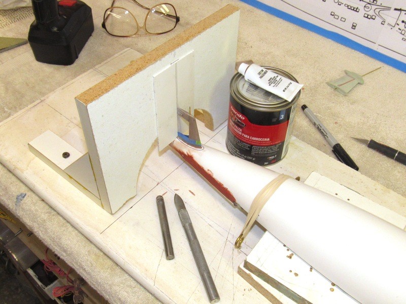
Using the lower hull, specifically its stern, to give form to the Bondo fillet that was to be applied to the root of the two vertical stabilizers, the area under which the fillets would be formed was waxed and the hull suspended over a mold-board and the vertical fence (previously used to mark off the radial lines that denoted where the bow and stern pieces would be removed) pressed into service to provide the fore-aft; side-to-side alignment gauge to insure everything was plumb as the applied and screeded Bondo fillet was built up around the base of a stabilizer.
(I got your run-on sentence, right here, pal … grabbing crotch!)
 Who is John Galt?
Comment
-
Initially, just a little Bondo was used to adhere the stabilizer master to the hull – the weak bond (the wax preventing a sure bond) of the Bondo to the hull would insure that the eventual fillet stuck to only the sides of the stabilizer, not the hull during disassembly. Anyway, that was my hope, I did manage to damage the first fillet during removal, but it was fixable. A bit more wax on the other vertical stabilizer, and the part popped off the hull with no damage to the fillet.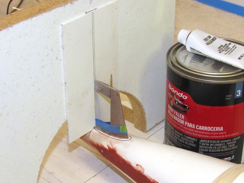
It took about three passes with fresh Bondo pushed into shape with a dapping tool of the correct radius. Work went quickly. Note how the masking tape on the sides of the stabilizer has its edge right were the upper edge of the screeded Bondo terminated as guided by the dapping tool. That tape saved me a lot of work.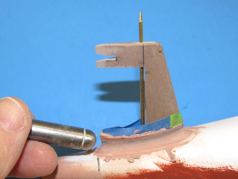
And here is the completed fillet applied to the upper vertical stabilizer master. This picture is a bit of a cheat: some of the fillet material broke off as I pulled the stabilizer off the hull – not enough wax on the hull, apparently. However, I was able to remove the errant piece of fillet off the hull and glue it to the stabilizer where it belonged. A little work with more Bondo and file, and the fix was near perfect.I’ve re-mounted the filleted stabilizer to the hull for this group shot which illustrates the previous work done on the horizontal stabilizers – cast resin pieces pressed into service as masters; a look at the lower vertical stabilizer awaiting its turn on the hulls stern for its fillet; and the two detached rudders.
Who is John Galt?Comment


 Tweet
Tweet


Comment